Constant current source design

Paul Andrews


Tomasz Kowalczyk

Laurence Wilkins
Yes, I agree with Tomasz, the first circuit shown in the article he links to is the way to do it. Advantages: No "wasted" current draw, cheap and easy. Ignore the comments in that article about the problems of voltage drop - that might be important when you've only got 5V to play with, but with 200V on tap... !!
Suggest RSense of 120 Ohms should regulate the current to 5mA, then make R1 anywhere between 100K and 220K. Not critical. Use a high voltage MPSA42 transistor or similar for T1, T2 can be any old jelly bean type.
While this constant current source will be inherrently short-circuit proof (the most current that will ever flow will be 5mA), be aware that under those conditions a humble MPSA42 will be dropping 1 Watt and will fry pretty quickly! Something a little beefier in the power stakes might then be a better choise.

gregebert
- I use a PMOS instead of PNP, mainly because it requires no drive-current.
- R1 & R2 are replaced with a pot to make the current adjustable.
- The above pot can driven from a small DC-DC converter (my preference), or between the HV supply & GND. There's essentially zero current for PMOS gate-drive, so high resistance values are fine. Not the case with PNP, though, due to finite base-currrent.
- A zener diode is added to clamp any spikes that may arise at the gate of the PMOS device. It's a paranoia item.
- A filter cap was added, in case there is unexpected noise from the DC DC converter, and also to suppress any very-short transient that may arise that are too fast for the zener to kick-in. (paranoia item).
- A large resistor across the PMOS to bleed any potential ESD. Without it, there is a remote possibility of charge-buildup. (paranoia item)
gregebert

gregebert
Tomasz Kowalczyk

Luka C
gregebert

robin bussell
> For
> example, http://tayloredge.com/storefront/1386_B7971SmartSocket/1386A.pdf
>
> Segment 11 in the datasheet is defined for a max current of 5.5mA, but
> the above schematic would produce (170V - 140V) / 24 kOhm = 1.25mA. This
> seems rather low?
and it seems plenty bright enough to my eyes. Occasionally when the sun
is full on the tubes through the window the pictures it produces can be
a bit less legible but that's likely the camera having to adjust the
sensitivity down due to bright reflections on the tubes.
Cheers,
Robin.
gregebert
Paul Andrews
ZY
gregebert
- If you use the R1//R2 voltage divider, you will need to account for base-current of additional regulators. This means smaller R1 & R2 values, hence more power dissipation in those resistors (heat).
- You can also use a PMOS device instead of the PNP [base--> gate, emitter --> source, collector --> drain]; the gate current will be zero. Just be careful about ESD handling procedures, and be sure to have plenty of voltage margin (Vds > 200V for Paul's circuit)
- You can omit R2, and replace R1 with a negative voltage supply; isolated DCDC converters are perfect for this. -5V for PNP, -12V for PMOS is a god choice. Remember: the gate or base must be negative with respect to the emitter.
Paul Andrews
BTW, how exactly would I drop 5V from 200V using a DCDC converter? I.e. which converter (part number?) and how would it be wired up (diagrams help, I'm a visual type of person).
Thanks in advance.
Maybe I should just do a masters in electronics.

JohnK
mentioned give it easily directly from your low voltage supply - I don't
think he meant you to use up your precious High Voltage. Presumably you are
running the high voltage generator DCDC conv off a low voltage? You aren't
getting High Volts dangerously from the mains?
John K
You received this message because you are subscribed to the Google Groups
"neonixie-l" group.
To unsubscribe from this group and stop receiving emails from it, send an
email to neonixie-l+...@googlegroups.com.
To post to this group, send an email to neoni...@googlegroups.com.
To view this discussion on the web, visit
https://groups.google.com/d/msgid/neonixie-l/c8b42ecf-2ec3-4b13-9bdf-60756b034537%40googlegroups.com.
For more options, visit https://groups.google.com/d/optout.
Paul Andrews
> To unsubscribe from this topic, visit https://groups.google.com/d/topic/neonixie-l/gbJ0Beiu66I/unsubscribe.
> To unsubscribe from this group and all its topics, send an email to neonixie-l+...@googlegroups.com.
JohnK
that both rails of teh 5V supply are insulated very well from earth/ground.
ie Floating.
Then you can wire each of its leads to a place that could be a voltage well
above [or below] earth/gnd. Let's wait for him to pipe up. I was only
replying early in case it put you on the right track.
Look into supplies that have "floating" outputs. Get that concept figured
out firmly. [I noticed that you said you are willing to learn.]
jk
gregebert
- If you are using PNPs, be mindful of the base current. It may force you to use lower-value potentiometers (ie,below 1K).
- If you use PMOS, there is no current so just use any pot you have; anything from 1K to 100K or more is fine. Best to add a zener diode to clamp any potential voltage spikes that could happen (startup/shutdown transients, ESD, etc) to protect the PMOS. The zener voltage needs to be greater than the DC-DC converters output voltage, AND less than the max Vgs specified in the PMOS datasheet.
Paul Andrews

I also tried this current mirror, which was a complete disaster - BY my calculations, the current should have been limited to about 0.5mA (200/390K), but it grew rapidly to about 30mA before I managed to break the connection, I don't really understand why. But now I do understand why there is no Re in those mirrors - Vb in the equations in my first post is equal to k (i.e. Vbe) so the value for Re is always zero?

Again, many thanks for all of your input. I'm going to try the current limiter that Tomasz suggested earlier next. Then on to PMOS.
gregebert
Paul Andrews

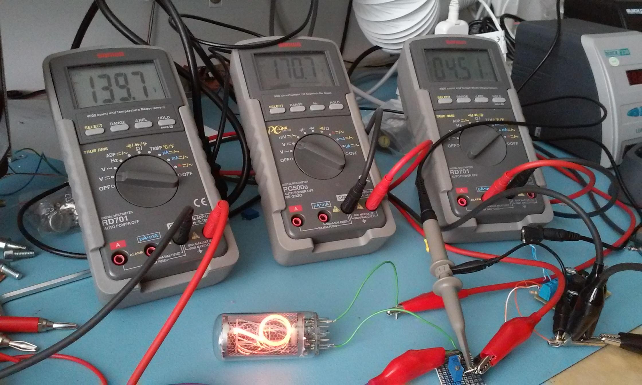
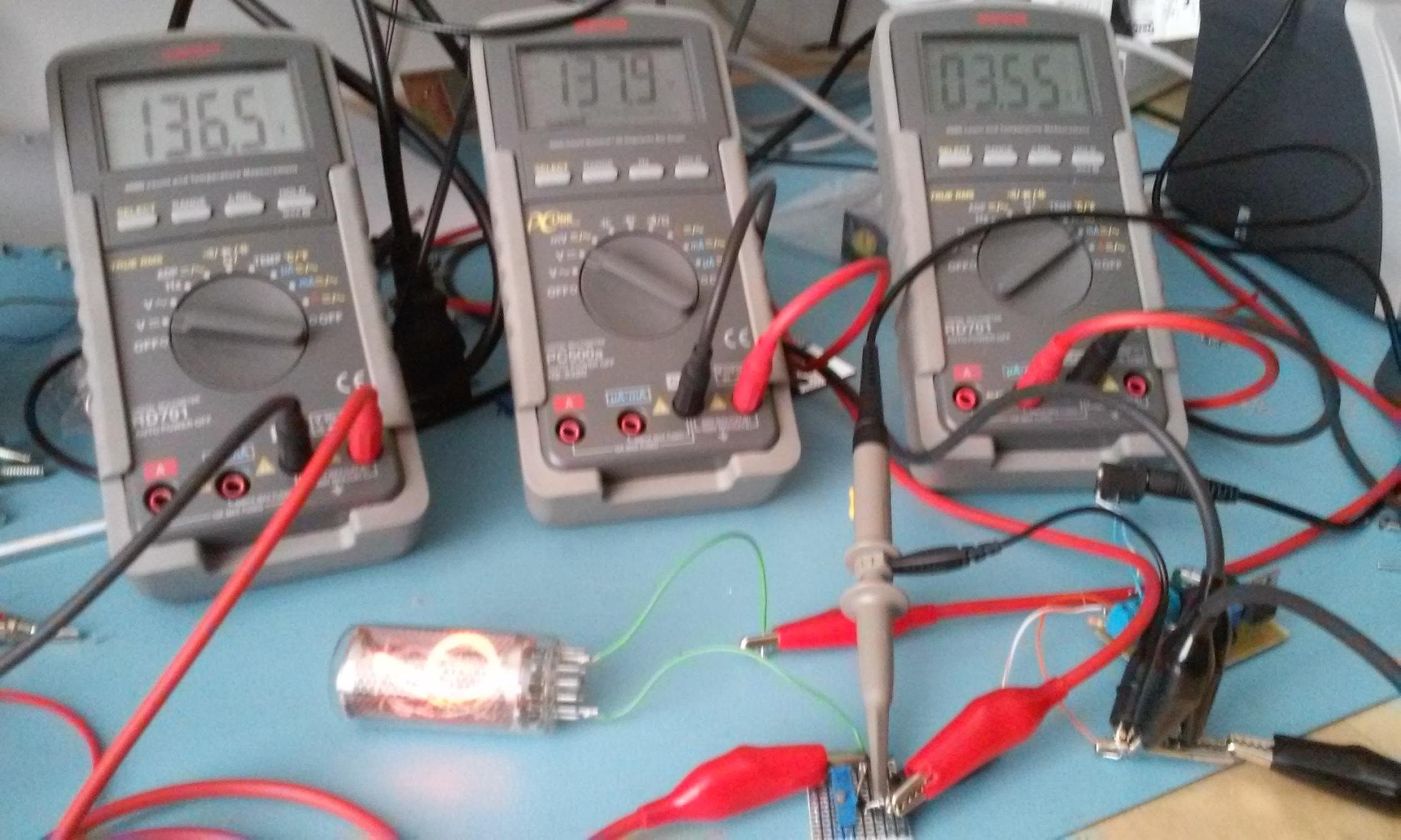
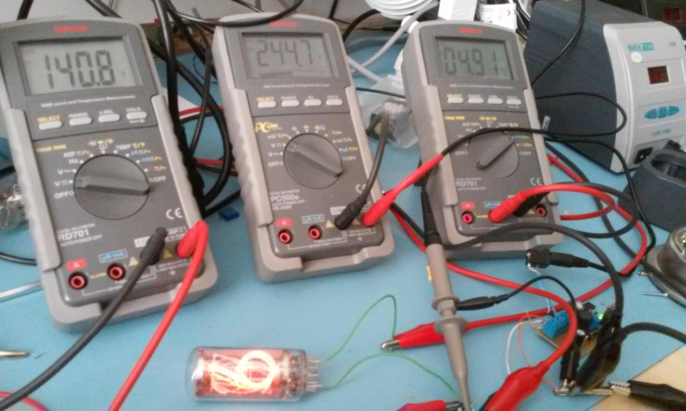
Next I tried the current limiter as described in several places, but in particular here as suggested by Tomasz. I used an Rsense (R3) of 330 Ohms as I wanted 2mA. This was not successful. With test loads it delivers <2mA (or exactly 2mA for a short circuit!). So I tried a 6844A nixie (which is what started off this whole current source thing). It delivered approx 0.5mA, so the tube barely lit.

Paul Andrews
gregebert
Tomasz Kowalczyk
Tomasz Kowalczyk
Tomasz Kowalczyk
Paul Andrews

VGS(th) is the gate threshold voltage of the MOSFET, IDSS is the on current at VGS = 0 V and ID is the required
current.
There are plenty of these around with suitable voltage characteristics.
Paul Andrews
gregebert
Paul Andrews
My concern with current limiters that rely heavily upon the datasheet specs (Vgs for Depletion-mode regulator; Vbe for current-mirror) is that variations due to process & temperature will have significant impact on the actual current. Using a slightly more complex+costly design will mitigate this; well-worth it in my opinion when you consider the value of the tubes you are protecting.
--
You received this message because you are subscribed to a topic in the Google Groups "neonixie-l" group.
To unsubscribe from this topic, visit https://groups.google.com/d/topic/neonixie-l/gbJ0Beiu66I/unsubscribe.
To unsubscribe from this group and all its topics, send an email to neonixie-l+...@googlegroups.com.
To post to this group, send email to neoni...@googlegroups.com.
To view this discussion on the web, visit https://groups.google.com/d/msgid/neonixie-l/5c9c7941-efba-4967-acee-24c8701874b4%40googlegroups.com.
Tomasz Kowalczyk
I'll test J-FET current limitter with a hot air gun - how it behaves in temperature range of 20-150°C, both with 5V and 30V dropping on it.

GastonP
Tomasz Kowalczyk

Dekatron42
Tomasz Kowalczyk

John Rehwinkel
- while testing it I found out that striking voltage of tubes is a max value - I've tested one Z567M and one LC-631, they both strike with voltages lower than their normal maintaing voltage!
I wonder if this low striking voltage is common among different tubes or does the striking voltage change with temperature.
gregebert
John Rehwinkel
My wristwatch uses a 'boost' approach to ionize the display above 180V for 25msec, then throttles back between 140 to 160V after the display is stable. The saved energy is significant. It's 3-1/2 digits, direct-drive, and uses NPN current-regulators for each segment (24 total).
My bench prototype has been running for over 2 years now on the original charge to the battery (3.7V Li-ion, 1050mA-hr). I dont display the time more than a few times per week, but the fact it's still operating is amusing. BTW, the battery was not new, either. It was used for a few years in my cellphone so it's capacity is diminished.
gregebert
Tomasz Kowalczyk
JohnK
--
You received this message because you are subscribed to the Google Groups "neonixie-l" group.
To unsubscribe from this group and stop receiving emails from it, send an email to neonixie-l+...@googlegroups.com.
To post to this group, send email to neoni...@googlegroups.com.
To view this discussion on the web, visit https://groups.google.com/d/msgid/neonixie-l/aa645b68-5fa0-4212-8b9d-b75f69e6794f%40googlegroups.com.
Paul Andrews

M W

Terry S

Nick Sargeant
Oh, I could tell you some stories. When we did some early ships of advanced workstations to universities, I had a bunch of complaints from Cambridge University that their optical mice were failing randomly. I phoned the lab tec to find out what was going on .. these mice used two colours of LED, and a reflective pad with a grid of lines on. So, he told me that one in particular was random, jerky, and sometimes the mouse pointer wouldn't move at all. I asked him for the serial number of the failing mouse (thinking was there a bad batch?) .. he said Hang on, just have to shut the blinds so I can read the number - sunlight is too strong ... (a long pause) ... oh, wait, it's working now.
And that was a leading academic institution. Speaks to the difference between intelligence and common sense, I feel.
I had another complaint from a customer somewhere in NY state that one of my workstations had a CRT screen where the image wobbled. Just the one. .. on a hunch I asked him where it was in the room. Next to a wall, he said. Can you move it away from the wall? Oh, look, it has stopped wobbling now. What's the other side of that wall? A huge transformer serving power to the building apparently. *sigh*
Paul Andrews
On Friday, April 7, 2017 at 5:34:49 PM UTC-4, Paul Andrews wrote:
gregebert
Paul Andrews
--
You received this message because you are subscribed to a topic in the Google Groups "neonixie-l" group.
To unsubscribe from this topic, visit https://groups.google.com/d/topic/neonixie-l/gbJ0Beiu66I/unsubscribe.
To unsubscribe from this group and all its topics, send an email to neonixie-l+...@googlegroups.com.
To view this discussion on the web, visit https://groups.google.com/d/msgid/neonixie-l/820f82b0-8b70-4c70-b589-d224f70db2f3%40googlegroups.com.
gregebert
Paul Andrews
On Saturday, March 25, 2017 at 12:30:53 PM UTC-4, gregebert wrote:
That's basically what I use in my designs. I'll highlight the differences:
- I use a PMOS instead of PNP, mainly because it requires no drive-current.
- R1 & R2 are replaced with a pot to make the current adjustable.
- The above pot can driven from a small DC-DC converter (my preference), or between the HV supply & GND. There's essentially zero current for PMOS gate-drive, so high resistance values are fine. Not the case with PNP, though, due to finite base-currrent.
- A zener diode is added to clamp any spikes that may arise at the gate of the PMOS device. It's a paranoia item.
- A filter cap was added, in case there is unexpected noise from the DC DC converter, and also to suppress any very-short transient that may arise that are too fast for the zener to kick-in. (paranoia item).
- A large resistor across the PMOS to bleed any potential ESD. Without it, there is a remote possibility of charge-buildup. (paranoia item)
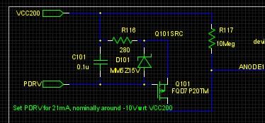
So, this circuit is replicated for each anode. When multiple anodes are driven, they all share the same gate-drive signal, which I call PDRV on the attached schematic.
gregebert
Next, you want some adjustment range for the anode current. I set the nominal gate voltage at 10V. That gives +/- 2V of range to adjust the anode current without changing resistors.
Next, from the datasheet, you need to find Vgs(on) for the MOSFET. It's usually plotted on a curve. For the FQD7P20TM that I use, it's about 4V (see the transfer characteristics curve).
Next, you need the target anode current. For a Burroughs 5092, it's 2.2mA.
The voltage-drop across the resistor is 10V - Vgs(on); in this case, it's 6V. Now you can solve for the resistor value:
R=V/I = 6/0.0022 = 2727 ohms. The nearest standard value = 2.7K.
Sanity-check the power in the resistor: P=I^2R; in this case, P=13mW, so even with tiny surface-mount devices you are fine.
You should also sanity-check the PMOS transistor worst-case power dissipation. Assume a ridiculously low nixie voltage of 125V. The voltage across the PMOS is Supply_voltage - Nixie_voltage - Resistor_voltage = 200-125-6.
PMOS power = Max voltage * typical current = 69*0.0022 = 150mW.
This device has a Theta j-a of 110C/W, so the temp-rise = 110*0.15 = 17 degrees. Plenty of margin here.
Luka C
gregebert
Luka C

Nick
gregebert
Luka C
gregebert
Tomasz Kowalczyk
gregebert
Nick
@Nick - I know that cathode current control per segment might seem a bit of an overkill, but as @greg said, considering the price of the tubes, I think we should do our best to meet all of the datasheet specs if possible. And if you carefully look at the datasheet, consider the case you want to display a character like "*" (asterisk), then add together the currents of each segment from the datasheet and it will exceed the maximum anode current defined in the same datasheet, this is why each cathode current should be adjusted so that if you add them all together, the sum will be lower than the maximum anode current (of course, how much this really impacts the life of the tube will remain a mystery I guess, but we should still be careful)