Questions about voltage doubling

Paul Andrews

Here are the waveforms for out, outdouble, outneg and the PS1 (the cyan trace) :

- Vout is around 148V.
- The cyan trace goes to -62V.
- Outneg is -205V. If I subtract the -62V, then I get -143V (i.e. close to -148V).
- Outdouble is 351V. If I add the -62V I get 289V (i.e. roughly double the 148V).
I don't now where to start to think about this, so any help would be very appreciated.
Thanks - Paul

gregebert
gregebert
gregebert
Paul Andrews
On Friday, January 5, 2018 at 8:01:29 PM UTC-5, gregebert wrote:
A bit more commentary on the flyback converter here....when you see the PS1 transformer pin go negative, it's probably doing so when the MOSFET turns on, correct ?
That's normal transformer behavior, but I will caution you that if you harvest energy from it (during the ON cycle) there will be less energy available for the positive supply during the OFF cycle. It doesn't cause any harm, but it will cause the circuit to behave differently versus generic equations for a flyback converter. The other thing to know is that the negative voltage you are using is fundamentally limited by the supply voltage and the turns-ratio of the transformer, whereas the output of the flyback transformer on the positive cycle is limited by the feedback-control.
Things get real interesting when the transformer starts to oscillate with the filter capacitor. They get worse with higher turns-ratio as secondary inductance is proportional to number-of-turns-squared.
Be sure to play around with voltage, frequency, duty-cycle, rise & fall-times for the gate of the NMOS driver, and parasitics. I guarantee you will learn a lot from running a lot of simulations, and it will prepare you for reality when you bench-test it. These things always behave so much worse under load.
gregebert

Michail Wilson
Tony,
https://youtu.be/pvbAqrQQiIU?t=3m30s
Maybe posted before, but just ran across it.
Floating nixie clock – When are these going to start shipping?
https://www.kickstarter.com/projects/lasermad/time-flies-levitating-nixie-clock
Michail
Paul Andrews
--
You received this message because you are subscribed to a topic in the Google Groups "neonixie-l" group.
To unsubscribe from this topic, visit https://groups.google.com/d/topic/neonixie-l/gE8ei40HMDs/unsubscribe.
To unsubscribe from this group and all its topics, send an email to neonixie-l+unsubscribe@googlegroups.com.
To post to this group, send email to neoni...@googlegroups.com.
To view this discussion on the web, visit https://groups.google.com/d/msgid/neonixie-l/00fd01d387fa%248fd1ee30%24af75ca90%24%40com.
For more options, visit https://groups.google.com/d/optout.
Michail Wilson
Waiting on mine. J
Thanks, I didn’t know the shop exists. Need a tic-tac-toe now.
(Unfortunately, I purchased the chess kit many years ago, but didn’t assemble and went through a house fire – no idea how much of the kit I have anymore.)
Michail Wilson
From: neoni...@googlegroups.com [mailto:neoni...@googlegroups.com] On Behalf Of Paul Andrews
Sent: Sunday, January 07, 2018 1:32 PM
To: 'Terry S' via neonixie-l
Subject: Re: [neonixie-l] Lasermad
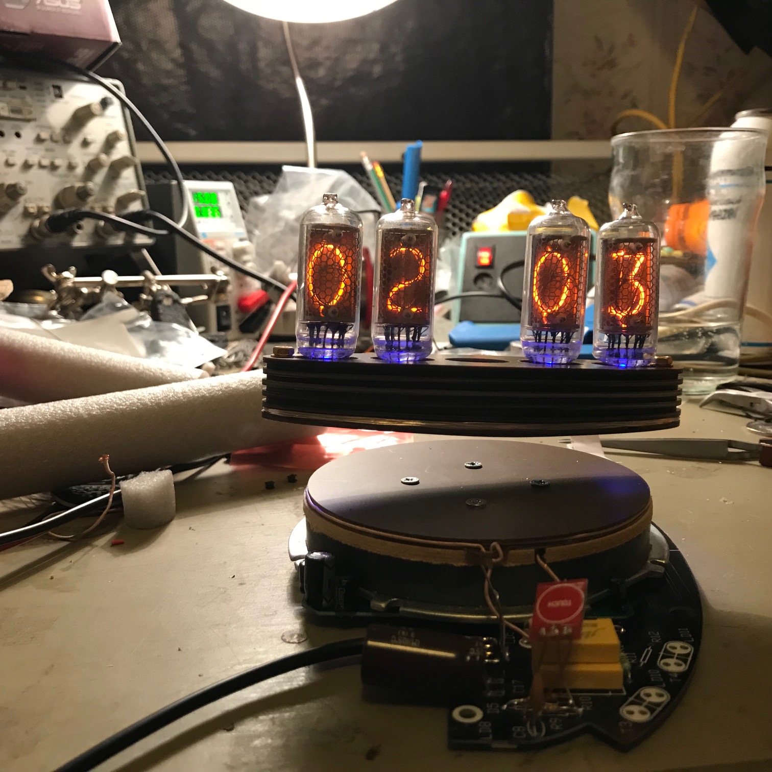
They are already shipping. I am part way through building one: http://www.lasermad.com/shop/shop/
| Virus-free. www.avg.com |
On Sun, Jan 7, 2018 at 4:00 PM, 'Michail Wilson' via neonixie-l <neoni...@googlegroups.com> wrote:
Tony,
https://youtu.be/pvbAqrQQiIU?t=3m30s
Maybe posted before, but just ran across it.
Floating nixie clock – When are these going to start shipping?
https://www.kickstarter.com/projects/lasermad/time-flies-levitating-nixie-clock
Michail
--
You received this message because you are subscribed to a topic in the Google Groups "neonixie-l" group.
To unsubscribe from this topic, visit https://groups.google.com/d/topic/neonixie-l/gE8ei40HMDs/unsubscribe.
To unsubscribe from this group and all its topics, send an email to neonixie-l+...@googlegroups.com.
To post to this group, send email to neoni...@googlegroups.com.
To view this discussion on the web, visit https://groups.google.com/d/msgid/neonixie-l/00fd01d387fa%248fd1ee30%24af75ca90%24%40com.
For more options, visit https://groups.google.com/d/optout.
--
You received this message because you are subscribed to the Google Groups "neonixie-l" group.
To unsubscribe from this group and stop receiving emails from it, send an email to neonixie-l+...@googlegroups.com.
To post to this group, send email to neoni...@googlegroups.com.
To view this discussion on the web, visit https://groups.google.com/d/msgid/neonixie-l/CABCPn3jo-FdKewh-GD4L%3D6FbccWYTijr229q1NgwVzKaQz_mtA%40mail.gmail.com.

Cqr
Kind Regards,
Robin Bussell
Research & Development Engineer 
Email: Rob...@excelerate.info
Tel: +44 (0)845 658 5747
Mobile: +44 (0)776 016 4551
Website: www.excelerate-group.com
Website: www.exceleratemarine.com ![]()
![]()
![]()
Head Office Cardiff UK, Subsidiaries and offices in Melbourne, Perth, Washington
DC, Abu Dhabi and Cannes.
Company No: 4260093
IMPORTANT - The information transmitted in this email is intended only for the person or entity to which it is addressed
and may contain confidential and/or priviledged material. Any review, retransmission, dissemination or other use of, or
taking of any action in reliance upon, this information by any persons or entities other than the intended recipient is prohibited.
If you received this in error, please delete this email and inform in...@excelerate.info immediately.
You received this message because you are subscribed to the Google Groups "neonixie-l" group.
To unsubscribe from this group and stop receiving emails from it, send an email to neonixie-l+...@googlegroups.com.
To post to this group, send email to neoni...@googlegroups.com.
To view this discussion on the web, visit https://groups.google.com/d/msgid/neonixie-l/CABCPn3jo-FdKewh-GD4L%3D6FbccWYTijr229q1NgwVzKaQz_mtA%40mail.gmail.com.

Cqr
To view this discussion on the web, visit https://groups.google.com/d/msgid/neonixie-l/8E7BA740-4EEC-4CD4-9394-135E2AF91272%40gmail.com.
<Video.MOV>
I’m waiting for the base case instructions too....:-)Sent from my iPhone
Me too :)All I need to do now is add the symbol tube and assemble the base case, once instructions are posted.
To view this discussion on the web, visit https://groups.google.com/d/msgid/neonixie-l/8360AA54-8BED-48DA-AFE8-7CFB7E68E621%40cqr-ltd.com.
--
You received this message because you are subscribed to the Google Groups "neonixie-l" group.
To unsubscribe from this group and stop receiving emails from it, send an email to neonixie-l+...@googlegroups.com.
To post to this group, send email to neoni...@googlegroups.com.
To view this discussion on the web, visit https://groups.google.com/d/msgid/neonixie-l/8E7BA740-4EEC-4CD4-9394-135E2AF91272%40gmail.com.
Nicholas Stock
To view this discussion on the web, visit https://groups.google.com/d/msgid/neonixie-l/EE14DE53-5C0B-400C-BA3C-78D4983B7FFF%40cqr-ltd.com.
Paul Andrews
gregebert


David Forbes
I learned a lot about voltage doublers and flyback transformers when I
designed my scope clock power supply back in 2000. The goal was a
-1.5kV supply, so I used a 10x multiplier. I also used a positive
doubler on that winding to make +300V for the deflection. However, in
order to get good regulation of all the outputs (I used six windings!)
I found that I had to use doublers on all outputs. This means that the
supply isn't a flyback converter, nor a forward converter, but a
combination of both.
I like to think that I made a new switching power supply topology,
which I will merrily believe until someone shows me that I'm wrong.