Increasing output current limit on MAX1771 power supply design
103 views
Skip to first unread message

Luka C
Jan 16, 2019, 10:29:23 AM1/16/19
to neonixie-l
Greetings everyone,
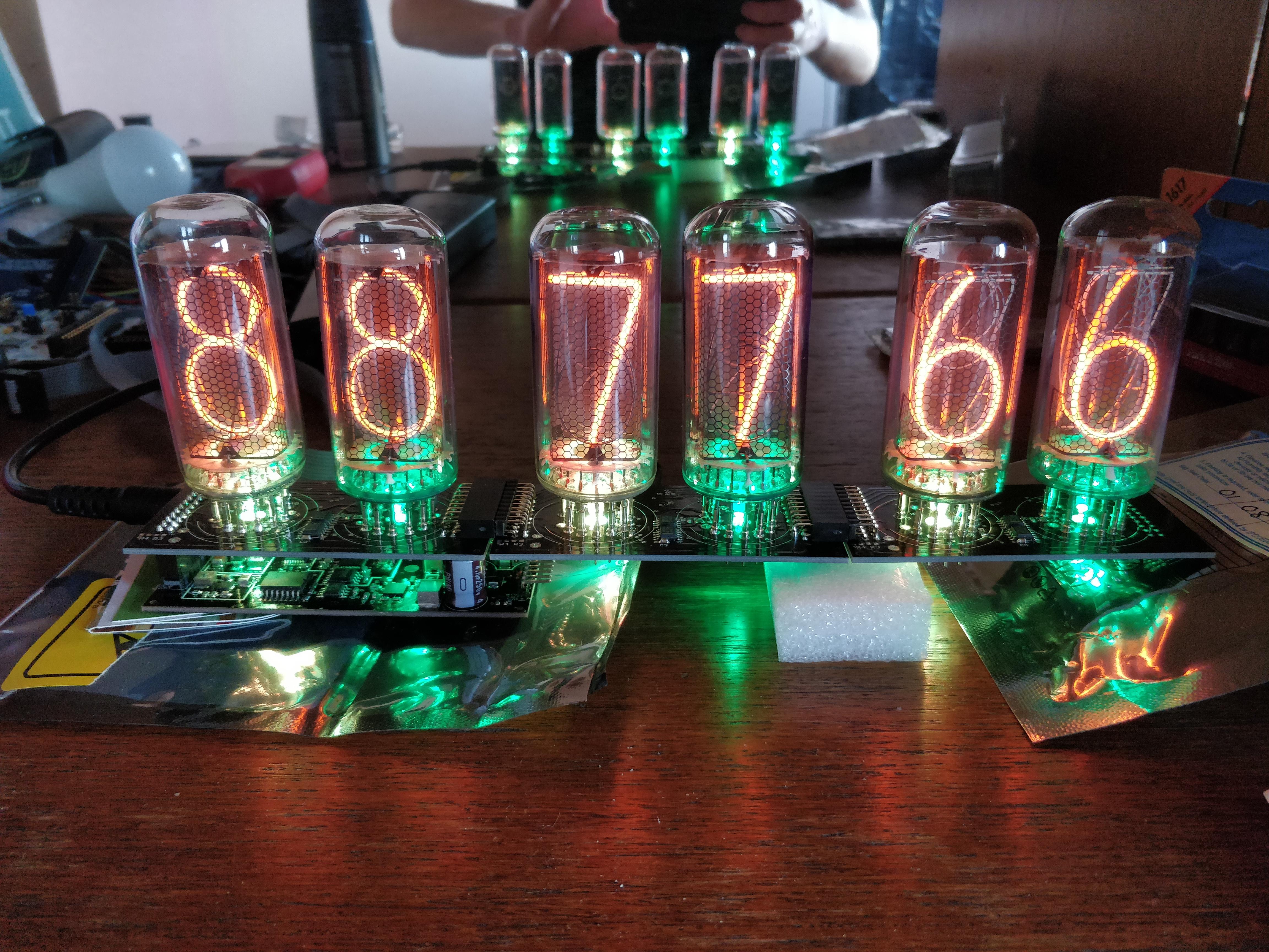
It's been a long time since I posted here last time and I've completed my modular clock design since then (photo attached). The main idea is to have a compact smart single "control board" which you can then add different number of daisy chained "display boards" for various tubes. Now, for the HV power supply, I've used a MAX1771 design presented here: https://desmith.net/NMdS/Electronics/NixiePSU.html . Tested it with 6x IN-18 tubes and it drives them at 5mA per tube fine. Now, I'd like to modify the power supply (without changing the board layout, considering all components are SMD) so that it can power 6x B7971 tubes (at ~17mA per tube with all segments lit is what I have in plan). The link with the power supply description contains a paragraph on how to expand the design so that it can handle such currents. The thing is that since the website was published, the FET proposed there is no longer in production and the inductor is not compatible with the SMD layout (the once that author proposes for higher current is a bobbin type).
After doing a little digging on replacement components, I've come up with:
1. Replacement FET candidate: FQP22N30 (http://www.mouser.com/ds/2/149/FQP22N30-1009534.pdf) , the difference being that this FET has a maximum drain current of 21A, while the discontinued one the author suggests has 32A.
2. Replacement inductor candidate: SRP1265A-470M (https://www.digikey.com/product-detail/en/bourns-inc/SRP1265A-470M/SRP1265A-470MCT-ND/4876720) , Irms = 6.5A, Isat = 9.5A , original one suggested by the author has Idc(max) = 8.5A. The new replacement candidate has a max DC resistance of 90mΩ, while the original one has 20mΩ (this would decrease efficiency somewhat, but there doesn't seem to be any footprint-compatibile inductor with lower DC resistance?).
3. Rsense 0.025Ω 2010 rated at 1W.
Do you think this would work?
Thanks in advance and best regards,
Luka

SWISSNIXIE - Jonathan F.
Jan 16, 2019, 12:12:28 PM1/16/19
to neonixie-l
Why do you plan to drive all the segments of a B7971? Do you realized that this would need a resistor on each cathode? If you use one anode resistor, the current changes depending on how many cathodes are grounded. This results either in tube damage or not working/darker display. I suggest to multiplex this tube.
About the mosfet, 21A or even 32A is overkill, but the problem is, that usually mosfets that have a low RDSon and GateChange, have a lot of current rated. If you use a Rsense of 25mOhm, the maximum current would be areound 3.5A@5V, so a mosfet with a few amps more should work fine, but low current fets usually have higher RDSon. This is why most DC/DC Converters use overkill Mosfet.
Rdson and GateChange influence the efficiency of the circuit, so lower is better, your chosen mosfet has 160mOhm, you could go lower. I've used the FDPF44N25 a few times:
The Inductor looks fine.
Luka C
Jan 16, 2019, 1:46:19 PM1/16/19
to neonixie-l
Thank you very much for providing valuable information.
As for B7971, what I meant to say is that 17mA would be the maximum current per tube (sum of current from each cathode) in case all segments are lit up at the same time (although this will rarely happen, obviously) and thus, that the power supply should handle 6x 17mA current when modified. I am aware that each segment has a specific maximum current defined as per datasheet, I have implemented current control in each cathode, as per @gregebert's suggestion last time we discussed it. I'm talking about a different "display board" for B7971 here, I don't plan to use the same one I use for IN-18 of course.

gregebert
Jan 16, 2019, 3:34:51 PM1/16/19
to neonixie-l
Just to elaborate a bit more, the individual segment currents of a b7971 are different, due to different lengths. Since these tubes are getting quite rare, not to mention expensive, I also recommend anode-current limiting in addition to the individual cathode drivers. Per the datasheet, the maximum current for a b7971 21mA and individual segment currents range from 4 to 6mA. So the '8' character would draw 32mA (violating datasheet spec of 21mA) if you simply drive the segments at their rated current. In my case, I slightly decreased the segment currents below datasheet limits based on visual testing.
I have 8 tubes running in my 7971 clock; for my HV supply I rectified+filtered the AC-line voltage (about +170VDC), and boosted it by another 24V with a small DC supply. That's around 170mA of current in the worst case. I admit this is a dangerous thing to do if you dont know what your're doing with regard to safety, etc. But in my opinion, anyone talented enough to build their own nixie clock will follow good circuit-design practices with adequate fuses, surge protection, shielding, and ventilation. None of the six 'hot chassis' clocks I've built so far has had any component failure, other than a nixie tube (and even that is rare, with 2 tubes out of 47 getting dark coating inside the glass).

Nick
Jan 16, 2019, 5:23:30 PM1/16/19
to neoni...@googlegroups.com
Ah! My page - thanks for pointing out that the recommended FET is out of production. I'll update the BOM.
The FET that Jonathan mentions looks fine.
Cheers
Nick
Luka C
Jan 25, 2019, 3:27:04 PM1/25/19
to neonixie-l
@gregebert Thank you for the anode current limit suggestion. However, I have already produced the board so I might try it out in some future prototype. I have, however, scaled the current in each cathode down so that the sum of them all (when all segments light up) will not exceed the maximum current per tube. I do realize this will probably mean that the tube will have somewhat dimmer appearance, but hopefully not too much. I'll post results once I get to soldering the parts and trying it out!
@Nick Your site is a very valuable resource, this is my second clock using the HV power supply based on your design, the last one is now some two years in operation and works very well.
Reply all
Reply to author
Forward
0 new messages