Need help with a tubehobby clock overheating

Kiran Otter
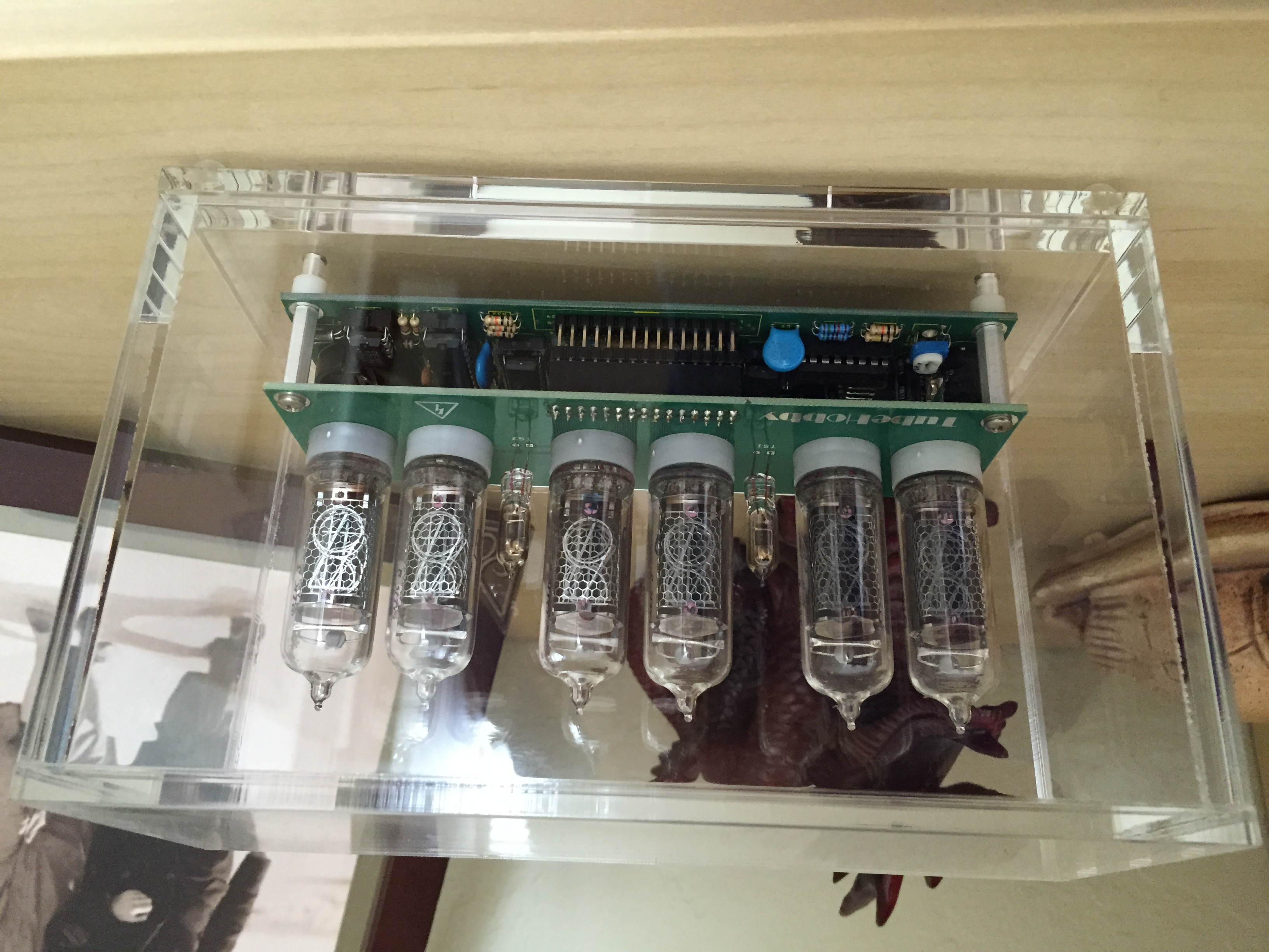
I've had a Tubehobby clock for several years, the NCV2.1 with the IN-18 tubes. In the past Jonas has helped, and I even shipped him the main board for him to repair, but he hasn't responded to my last request for help, so I thought I would ask here.
Recently, I started to notice that other digits in the tubes were partially lighting up, and eventually the fuse blew. My assumption was that the K155ID1 drivers had started to go, so I ordered six of them off eBay, and tried replacing them.. which isn't hard, everything is socketed. Well it didn't help, so I contacted Jonas. Jonas suggested replacing C6, which I did and it appeared to fix the problem.
Maybe a month later, I started to notice the left most digit was faintly showing numbers, and seemed to be influenced by the next to right digit. So I thought perhaps the drivers I got from eBay weren't good, so I swapped them around, trying to see if it made any difference. Unfortunately, I trashed the two original driver chips that came with the kit. So far swapping the drivers around among the six I have, hasn't changed anything.. or if it has, the digits lighting that shouldn't be have moved from tube to tube.
Well I let the clock run like this for a week or so, and one day I just happened to feel around the voltage regulator U1 (L7805CV).. and it's blazing hot. I put a temp probe on it and it's running at 140F in open air, and when I built the clock, I epoxied a heatsink to it. It never ever used to get this hot. In fact the clock has run for years in a closed enclosure with very little ventilation. It just never produced much heat at all. I swapped both driver chips for two others, and it still gets just as hot.
When the clock shuts off the display at night, the temp drops to just above room temperature.
So my guess is has to be one of two things I replaced; C6, or the driver chips. I think it's the drivers, and I'd like to get a pair from somewhere reputable so I can at least rule them out as the problem. I've seen some that appear to be ceramic, instead of plastic cased.. claimed to be 'milspec' but I donno if that's BS or what.
Any help is appreciated!
Kiran

Sture Nystrom
Measure the input voltage to your clock. If voltage from your DC wall adapter have risen 7805 regulator will go hot. Also high voltage to Nixie tubes might also rise if input voltage to clock is too high.
Sture
--
You received this message because you are subscribed to the Google Groups "neonixie-l" group.
To unsubscribe from this group and stop receiving emails from it, send an email to neonixie-l+...@googlegroups.com.
To post to this group, send email to neoni...@googlegroups.com.
To view this discussion on the web, visit https://groups.google.com/d/msgid/neonixie-l/a7625eb8-22e2-454e-91ea-8b7497882c22%40googlegroups.com.
For more options, visit https://groups.google.com/d/optout.

blkadder
Ron
Kiran Otter
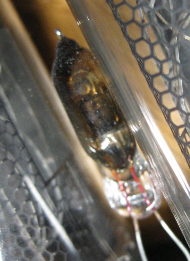
Something else I wanted to mention; the separator tubes (separating hours from minutes, minutes from seconds,) one of them is mostly black, and neither of them light properly. I'm wondering if they're the culprit. I'm going to remove them and see if it makes any difference.
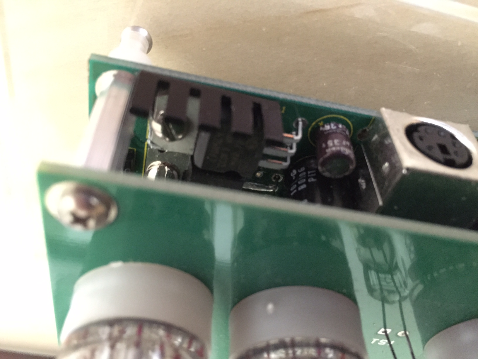
Also, I have the heatsink epoxied to both U1 and M1; maybe it's M1 that's getting hot, not U1? I'll use a infrared temp gun and see if I can distinguish which is getting so hot.
Thank you for the replies!
Kiran

JohnK
--
You received this message because you are subscribed to the Google Groups "neonixie-l" group.
To unsubscribe from this group and stop receiving emails from it, send an email to neonixie-l+...@googlegroups.com.
To post to this group, send email to neoni...@googlegroups.com.
To view this discussion on the web, visit https://groups.google.com/d/msgid/neonixie-l/c3192283-c525-4403-bed6-a3979a06f065%40googlegroups.com.

MichaelB
Kiran Otter
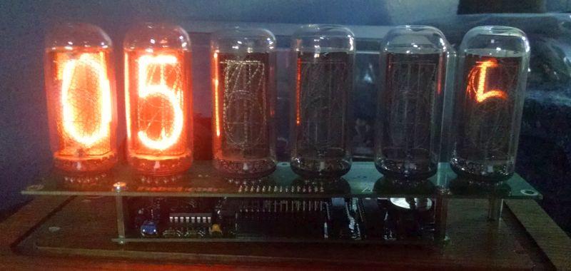
I still see some numbers/digits lighting faintly as the seconds tick by.. in the hour and minute digit.. 2 and 4 if you count the tubes left to right.
The temperature is now down to around 125F from 140F. Still way hotter than it used to be.
I've attached another picture so you can see how I epoxied the heatsink to M1 and U1.. and in retrospect it was probably a bad idea because now the heat is being transferred from U1 to M1.
Any suggestions on good driver chips? Or is it just a luck of the draw?
Kiran
Kiran Otter
Kiran Otter
Kiran
blkadder
Ron
MichaelB

Niek
MichaelB

Jeff Walton
Kiran
You received this message because you are subscribed to the Google Groups "neonixie-l" group.
To unsubscribe from this group and stop receiving emails from it, send an email to neonixie-l+...@googlegroups.com.
To post to this group, send email to neoni...@googlegroups.com.

Nicholas Stock
Sent from my iPhone
By the way, I'm open to recommendations on a different clock kit that will use my IN-18s. I haven't had much luck finding another make.
Kiran
--
Niek
Niek
Jeff Walton
Sorry, corrected link below. Phones are fun...
Kiran,
PV Electronics makes a nice kit. Their "Spectrum" model uses the IN-18 nixies and accepts a GPS and also has a motion sensor that turns off the high voltage when no one is around to extend the life of the tubes. Really nice feature!
They also have a couple different cases available for the Spectrum model.
I recently bought one and would recommend them. It runs nice and cool.
From: neoni...@googlegroups.com [mailto:neoni...@googlegroups.com] On Behalf Of Kiran Otter
Sent: Saturday, March 28, 2015 12:51 PM
To: neoni...@googlegroups.com
Subject: [neonixie-l] Re: Need help with a tubehobby clock overheating
By the way, I'm open to recommendations on a different clock kit that will use my IN-18s. I haven't had much luck finding another make.
Kiran
--
Jeff Walton
Here is a direct link to PV Electronics "Spectrum" clock kit that uses the IN-18 tubes:
http://www.pvelectronics.co.uk/index.php?main_page=product_info&cPath=18&products_id=157
Jeff W
From: neoni...@googlegroups.com [mailto:neoni...@googlegroups.com] On Behalf Of Kiran Otter
Sent: Saturday, March 28, 2015 12:51 PM
To: neoni...@googlegroups.com
Subject: [neonixie-l] Re: Need help with a tubehobby clock overheating
By the way, I'm open to recommendations on a different clock kit that will use my IN-18s. I haven't had much luck finding another make.
Kiran
--

gregebert
Kiran Otter
I do have a scope, however I'd be lying if I said I knew how to use it. I bought it used with the intention of learning how to use it, and it's sat since then. You could probably say I know enough about electronics to be dangerous. I know what resisters and capacitors and transistors do.. and I can somewhat read a schematic, but I wouldn't say I know much more beyond that.
That being said; I put my meter on the 7805 and there's a solid 5.042V coming from it. I then removed the fuse and measured the current across the fuse holder, and at most it peaked at 0.5A.
I've now snapped the heatsink off; the epoxy never came in contact with the leads to U1 or M1. And now I think I've discovered that it's M1 that's getting hot, not U1. Going from the solder side of the board, with the heatsink, the board was much hotter behind U1 before.. but with the heatsink gone, I can hit the case of U1 and M1 with the temp laser.. and M1 is about 85F.. U1 is about 96F.
Now I've increased the voltage to the tubes back to 170V (from 165V) and U1 seems maybe a degree cooler.
I'm going to kick myself if all it was was this heatsink I put on.. plus I don't understand how it was causing such a problem.
Here's a video of the numbers faintly lighting. In this case it matches the seconds.
https://www.dropbox.com/s/3ex4b070e2r3s5p/2015-03-28%2019.52.58.mp4?dl=0
Kiran Otter
Kiran Otter
U1 is ok, it's M1 that's getting quite hot. 109F now from the PCB side. It's hard to hit it on top because of the other PCB on top. But with the heatsink gone nothing is anywhere near as hot as it was before. Really makes no sense to me.
Kiran
MichaelB
Kiran Otter
I realize it's pretty faint, but this is the best it's been with the two driver chips I have in there now. With another pair, the left most tube constantly displayed a digit based on the 10s of seconds. This is why I think the drivers are a bit wonky.
So far both M1 and U1 are around 105-108F. I'll have to check it later when it's after 10pm and all 6 digits are in use.
Kiran
MichaelB
Seriously doubt you have bad driver chips. Those things are pretty bullet proof
Kiran Otter
I appreciate everyone's input. We'll see how long it goes like this.
Kiran
Niek
Kiran Otter
Yes, it's showing the seconds in the hour digit, and in the minutes digit.. though not as strongly. If I force it to display the date or number of hours on the tubes, I can see whatever is in the most-right tube, faintly in the next to left tube. And I swear I can see the 6 in the seconds tube coming on for like 4-5 seconds. Again, it's all really faint, so I assume it's not really a problem.
Before I swapped the driver chips around, I was getting faint digits in the left most tube. So it does seem to be driver related. But I think it's OK for now.
Is there a known good source for the driver chips? Someone on ebay?
Kiran
Niek
Nicholas Stock
Sent from my iPhone
--
You received this message because you are subscribed to the Google Groups "neonixie-l" group.
To unsubscribe from this group and stop receiving emails from it, send an email to neonixie-l+...@googlegroups.com.
To post to this group, send email to neoni...@googlegroups.com.
To view this discussion on the web, visit https://groups.google.com/d/msgid/neonixie-l/2a2ddbd2-87d6-4cc1-93fc-81dd50c2bc91%40googlegroups.com.

Terry Kennedy
I've had a Tubehobby clock for several years, the NCV2.1 with the IN-18 tubes. In the past Jonas has helped, and I even shipped him the main board for him to repair, but he hasn't responded to my last request for help, so I thought I would ask here.
Recently, I started to notice that other digits in the tubes were partially lighting up, and eventually the fuse blew. My assumption was that the K155ID1 drivers had started to go, so I ordered six of them off eBay, and tried replacing them.. which isn't hard, everything is socketed. Well it didn't help, so I contacted Jonas. Jonas suggested replacing C6, which I did and it appeared to fix the problem.
Nicholas Stock
--
You received this message because you are subscribed to the Google Groups "neonixie-l" group.
To unsubscribe from this group and stop receiving emails from it, send an email to neonixie-l+...@googlegroups.com.
To post to this group, send email to neoni...@googlegroups.com.
To view this discussion on the web, visit https://groups.google.com/d/msgid/neonixie-l/54a9ef2a-7475-456e-9ac0-996743cf166c%40googlegroups.com.

Dan Hollis
> On Saturday, March 28, 2015 at 7:55:48 AM UTC-4, Kiran Otter wrote:
>> Recently, I started to notice that other digits in the tubes were
>> partially lighting up, and eventually the fuse blew. My assumption was
>> that the K155ID1 drivers had started to go, so I ordered six of them off
>> eBay, and tried replacing them.. which isn't hard, everything is socketed.
>> Well it didn't help, so I contacted Jonas. Jonas suggested replacing C6,
>> which I did and it appeared to fix the problem.
> Yes, that kit tends to "eat" the HV filter cap. I've replaced it in
> multiple clocks multiple times. Eventually I suppose I'll just figure out
> how to get a Tayloredge HVPS module in there, and swap the supplies the
> next time the cap fails in each.
problem. Also good to know C6 is the likely culprit. My clock has been
sitting unused for a while.
-Dan
JohnK
----- Original Message -----From: Kiran OtterSent: Sunday, March 29, 2015 8:53 AMSubject: [neonixie-l] Re: Need help with a tubehobby clock overheating
--
You received this message because you are subscribed to the Google Groups "neonixie-l" group.
To unsubscribe from this group and stop receiving emails from it, send an email to neonixie-l+...@googlegroups.com.
To post to this group, send email to neoni...@googlegroups.com.
To view this discussion on the web, visit https://groups.google.com/d/msgid/neonixie-l/2a2ddbd2-87d6-4cc1-93fc-81dd50c2bc91%40googlegroups.com.

Jon

Dave
Your heat will go away from the regulator, completely.
You can get one shipped to you for less than $9.
Click here:
Traco regulator

Nick
I would 'scope the +5V rail making sure that all input filtering is off...
78xx regulators were notorious for singing if they coukd - hence the essential 100n input & output caps mounted right up against it....
Nick
Mich...@aol.com
Sorry, corrected link below. Phones are fun...
Kiran,
PV Electronics makes a nice kit. Their "Spectrum" model uses the IN-18 nixies and accepts a GPS and also has a motion sensor that turns off the high voltage when no one is around to extend the life of the tubes. Really nice feature!
They also have a couple different cases available for the Spectrum model.
I recently bought one and would recommend them. It runs nice and cool.
http://www.pvelectronics.co.uk
Jeff Walton
From: neoni...@googlegroups.com [mailto:neoni...@googlegroups.com] On Behalf Of Kiran Otter
Sent: Saturday, March 28, 2015 12:51 PM
To: neoni...@googlegroups.com
Subject: [neonixie-l] Re: Need help with a tubehobby clock overheating
By the way, I'm open to recommendations on a different clock kit that will use my IN-18s. I haven't had much luck finding another make.
Kiran
--
You received this message because you are subscribed to the Google Groups "neonixie-l" group.
To unsubscribe from this group and stop receiving emails from it, send an email to neonixie-l+...@googlegroups.com.
To post to this group, send email to neoni...@googlegroups.com.
To view this discussion on the web, visit https://groups.google.com/d/msgid/neonixie-l/bf9c36af-c129-4de0-a3fa-7b8423d521b5%40googlegroups.com.
For more options, visit https://groups.google.com/d/optout.
--
You received this message because you are subscribed to the Google Groups "neonixie-l" group.
To unsubscribe from this group and stop receiving emails from it, send an email to neonixie-l+...@googlegroups.com.
To post to this group, send email to neoni...@googlegroups.com.
To view this discussion on the web, visit https://groups.google.com/d/msgid/neonixie-l/5516fdc9.5a876b0a.176f.ffff9e7f%40mx.google.com.
Kiran Otter
I don't know how it could have become conductive across the cases of M1 & U1.. if it did, that's a neat trick. But removing it certainly seems to have made some difference.
Using a laser temperature probe, M1 seems fine.. but U1 definitely seems cranky.. and it's heating the board up all around that entire end to ~110F. Again, I never noticed it getting this hot.
To answer Johnk's question; the heatsink and epoxy weren't touching anything metallic, and I originally added it because I thought M1 & U1 were getting pretty warm from the start when I built it, and figured it wouldn't hurt to add it. But maybe over time.. it started to conduct between them somehow. I don't know.
Jon; thanks for that info. I'll try one of the 7805 alternatives you mentioned.
Nick; I'll drag out my scope and see if it even still works, and see if I can't check the 7805 with it. I might have a question or two on using the scope. :D
So far, right now with a little fan blowing over the M1/U1 area.. the whole thing is keeping cool. Barely running above 90F anywhere I check. If I turn off the fan, it shoots up past 120F. I turned the fan back on at that point.
Niek; I re-enabled the leading zero, and still see the same thing. In fact when going through the settings, I was able to catch the attached pic of the right most tube showing what was in the next-to-left tube. So it seems to go both ways.
Kiran
Jeff Walton
Kiran,
If you get your scope running, check the output of U1 (7805 regulator) and look for a very flat DC. If you see any type of sawtooth or superimposed oscillation, replace C1. You can use a any higher value than 10uF as long as it physically fits and has a high enough voltage rating. Any visible oscillation superimposed on the output pin could cause the overheating and also could cause the phantom digit illumination as well as other issues. Just as was mentioned in a previous post regarding C6, C1 could also have dried out and a heated board in the same area will accelerate the dryout of any nearby electrolytic caps. C2 is also filtering the input to the 7805 and in the direct vicinity of your hot board. If it is dried out, it will also cause unwanted behavior.
Jeff Walton
From: neoni...@googlegroups.com [mailto:neoni...@googlegroups.com] On Behalf Of Kiran Otter
Sent: Sunday, March 29, 2015 12:56 PM
To: neoni...@googlegroups.com
Subject: [neonixie-l] Re: Need help with a tubehobby clock overheating
Something I want to note about how I used a heatsink; I epoxied it to the tops of the cases of M1 & U1; traditionally you'd bolt it to the back of the component but at the time I couldn't figure out a better way, and I had heatsink epoxy, so I just plastered it to the tops of the two components. It's been like that ever since I built the clock, and never did it get so hot that you couldn't touch it. Warm, yes.
--
You received this message because you are subscribed to the Google Groups "neonixie-l" group.
To unsubscribe from this group and stop receiving emails from it, send an email to neonixie-l+...@googlegroups.com.
To post to this group, send email to neoni...@googlegroups.com.
To view this discussion on the web, visit https://groups.google.com/d/msgid/neonixie-l/508e5b80-f513-4cfb-9d71-8a46ab09022e%40googlegroups.com.
Nick
I would, as soon as possible, add those two 100n caps on the legs of the 7805.
Nick
Nick
Kiran Otter
Would replacing the 7805 with a 'non-isolated dc/dc converter' like Jon suggested solve the problem too? I ask because I was going to try the Traco TSR 1-2450, or the Murata part (though I'm not sure it will fit.) I ordered both.
I'll get my scope out today and see what I can see.
Kiran
Nick de Smith
Nick
Sent from my Android device with K-9 Mail. Please excuse my brevity.

GastonP
The LM340T series of regulators (of which the 7805 is a direct descendant) used to need one 10uF tantalum capacitor in the input and another in the output. Being tantalum caps known for its flashy temperament, it drove some designs to very interesting failure modes. I have seen datasheets that put the capacitors as unnecessary and other as must-have. I feel much better with suppression as a must-have and with the small size of SMD components, it seems nonsense not to install them.

taylorjpt
It is the same foot print as the 7805 and uses a 4-40 socket head cap screw for mounting. It does not require any external capacitors.
5.25 to 25V in, 5V out at 1A, heat loss is 250mW at 5W out/5.25-25V in. Compare to 7W dissipated by a 7805 at 12V in.
j...@tayloredge.com
Kiran Otter
At any rate, I'm not sure this scope will show me what I want to know; if the 7805 is oscillating. I can see it's putting out 5V by the scope, but I can't adjust it enough (or don't know how) to get it to show if it's oscillating. I can barely see a wave form but I have no idea how to read the frequency. If anyone wants to tell me what to set all the switches and knobs to, I'll give it a try.
Meanwhile JT was nice enough to send me one of his little 5V regulators. I'm waiting on a better desoldering iron to arrive before I butcher this clock any further.
Thanks for everyone's help so far!
Kiran
Kiran Otter
Kiran
On Saturday, March 28, 2015 at 7:55:48 AM UTC-4, Kiran Otter wrote:
Hi folks, glad to find this group!
I've had a Tubehobby clock for several years, the NCV2.1 with the IN-18 tubes. In the past Jonas has helped, and I even shipped him the main board for him to repair, but he hasn't responded to my last request for help, so I thought I would ask here.
Recently, I started to notice that other digits in the tubes were partially lighting up, and eventually the fuse blew. My assumption was that the K155ID1 drivers had started to go, so I ordered six of them off eBay, and tried replacing them.. which isn't hard, everything is socketed. Well it didn't help, so I contacted Jonas. Jonas suggested replacing C6, which I did and it appeared to fix the problem.
Maybe a month later, I started to notice the left most digit was faintly showing numbers, and seemed to be influenced by the next to right digit. So I thought perhaps the drivers I got from eBay weren't good, so I swapped them around, trying to see if it made any difference. Unfortunately, I trashed the two original driver chips that came with the kit. So far swapping the drivers around among the six I have, hasn't changed anything.. or if it has, the digits lighting that shouldn't be have moved from tube to tube.
Well I let the clock run like this for a week or so, and one day I just happened to feel around the voltage regulator U1 (L7805CV).. and it's blazing hot. I put a temp probe on it and it's running at 140F in open air, and when I built the clock, I epoxied a heatsink to it. It never ever used to get this hot. In fact the clock has run for years in a closed enclosure with very little ventilation. It just never produced much heat at all. I swapped both driver chips for two others, and it still gets just as hot.
When the clock shuts off the display at night, the temp drops to just above room temperature.
So my guess is has to be one of two things I replaced; C6, or the driver chips. I think it's the drivers, and I'd like to get a pair from somewhere reputable so I can at least rule them out as the problem. I've seen some that appear to be ceramic, instead of plastic cased.. claimed to be 'milspec' but I donno if that's BS or what.
Any help is appreciated!
Kiran
gregebert
Jeff Walton
Kiran,
A sawtooth waveform would point to a bad C1. A waveform of a much higher frequency would be from an oscillation and more superimposed on the DC.
As long as you are going to do some soldering anyway, you should just replace the 7805 with the drop-in switcher that you received from Tayloredge. It is MUCH more efficient. You could also replace C1 at the same time since you are already working on it. Saves you the work later if it is deteriorating. Bypass caps are also a good practice for circuits with high frequencies. Many modern board layouts that work with much higher frequencies (probably not in your clock) build-in circuit traces that are engineered to act in the same manner as a bypass but it won't hurt anything in a clock design to add the bypass caps to a power rail.
Many years ago, during my time with Texas Instruments, I sold hundreds of thousands of the little 78xx and 79xx series regulators into a lot of different applications. They were a new and novel solution for cheap and dirty regulation and efficiency was not a big deal back them. Today, the small drop-in replacements for the 78xx series are a much more modern and elegant solution when there is a small power budget.
Jeff Walton
From: neoni...@googlegroups.com [mailto:neoni...@googlegroups.com] On Behalf Of Kiran Otter
Sent: Saturday, April 04, 2015 1:52 PM
To: neoni...@googlegroups.com
Subject: [neonixie-l] Re: Need help with a tubehobby clock overheating
I should have said if I see oscillation from the 7805 that Jeff mentioned, pointing to a bad C1. I may just replace it regardless.
--
You received this message because you are subscribed to the Google Groups "neonixie-l" group.
To unsubscribe from this group and stop receiving emails from it, send an email to neonixie-l+...@googlegroups.com.
To post to this group, send email to neoni...@googlegroups.com.
To view this discussion on the web, visit https://groups.google.com/d/msgid/neonixie-l/db144a82-9537-4bb7-9a3b-6f1536af8c65%40googlegroups.com.
Kiran Otter
The ghosting numbers are still there but very faint.. but the MOSFET (M1, an IRF640) is still getting extremely hot. You know when a component gets so hot it has that hot-electronics smell? It's that hot. The voltage to the tubes is right on 170V. I didn't have to adjust it after replacing the two components.
Should I replace the MOSFET? Any other suggestions? :)
Kiran
Niek
Sture Nystrom
--
You received this message because you are subscribed to the Google Groups "neonixie-l" group.
To unsubscribe from this group and stop receiving emails from it, send an email to neonixie-l+...@googlegroups.com.
To post to this group, send email to neoni...@googlegroups.com.
To view this discussion on the web, visit https://groups.google.com/d/msgid/neonixie-l/a71bc0e6-d7a7-429c-95b4-416e7fa1a182%40googlegroups.com.
Kiran Otter
Sture, let me know if there's a way to test the inductor (270UH) somehow. Or of course, I can just replace it too.
This is kind of reaching the point where I might ditch this board and buy a new kit. I'd love to fix it, don't get me wrong, but I'm starting to have doubts of it being resolved.
Kiran
Niek
MichaelB
Kiran Otter
MichaelB.. I replaced C6 first, when I was having a problem with all of the tubes lighting up all sorts of numbers like crazy.. and then the fuse finally blew. It was Jonas' suggestion it was C6, and it fixed that particular problem.
With the heatsink epoxied to both the voltage regulator and the mosfet, I wrongly assumed it was the voltage regulator getting so hot. (Hard to tell even with a infrared temp probe.) But now that I've removed the heatsink and installed JT's voltage regulator board.. it's obvious it's the mosfet that's cooking.
I'll get these parts ordered and we'll see what happens!
Kiran
Kiran Otter
The inductor; I know it's 'inductance' is 270uh.. but what current rating? There's about 330 choices. :D I wish I could tell these things by looking at the schematic.
Is http://www.digikey.com/product-detail/en/RLB0914-271KL/RLB0914-271KL-ND/2352778 correct?
On the mosfet, there's only 2 choices.. one with a max power of 125W, the other 150W. I'm going on the assumption that the 150W would be better..?
I can't find the 2SA1266 transistor. Tried a cross-ref site and it gave me 213 choices. x.x
On the diode, there's two; 5ua@1000V or 10ua@1000V?
The capacitors I can figure out, at least.
Kiran
Nicholas Stock
Sent from my iPhone
--
You received this message because you are subscribed to the Google Groups "neonixie-l" group.
To unsubscribe from this group and stop receiving emails from it, send an email to neonixie-l+...@googlegroups.com.
To post to this group, send email to neoni...@googlegroups.com.
To view this discussion on the web, visit https://groups.google.com/d/msgid/neonixie-l/1fcacb70-ae75-4a8c-96d4-e0fdd8a36730%40googlegroups.com.

Charles MacDonald
> I can't find the 2SA1266 transistor. Tried a cross-ref site and it gave
> me 213 choices. x.x
It is a Japanese type. but their are probably hundreds that would work...
use the specs in the link above to screen on digikey for a similar one,
or order some from futurlec, although they tend to take a while to ship.
--
Charles MacDonald Stittsville Ontario
cm...@zeusprune.ca Just Beyond the Fringe
http://Charles.MacDonald.org/tubes
No Microsoft Products were used in sending this e-mail.
Kiran Otter
I replaced several parts per Nick's suggestion.. (in fact Nick was nice enough to send me the parts!) but in the end, the MOSFET is still getting super hot.
So today I'm sending the board to Nick for him to poke at it.
Thanks Nick!
Kiran
Dan Hollis
1) overheating
2) blue spots
3) singing due to multiplex frequency being in audible range
-Dan
> You received this message because you are subscribed to the Google Groups "neonixie-l" group.
> To unsubscribe from this group and stop receiving emails from it, send an email to neonixie-l+...@googlegroups.com.
> To view this discussion on the web, visit https://groups.google.com/d/msgid/neonixie-l/496e8fb9-31b2-4ff4-9aba-63afc0418305%40googlegroups.com.
Nicholas Stock
gregebert
MichaelB
http://www.badnixie.com/PV_Electronics_the_Spectrum.html
http://www.badnixie.com/The_Tangerine_Dream_%28Nocrotec_Blue_Dream%29.html
Anymore, Direct Drive is a must for me, because of the increased brightness and both of these are. The tube spacing is a little odd with the PV, but for my money, this kit is feature packed and the better value with a menu structure that makes a lot of horse sense. This clock is definitely for those of us that prefer to build our own enclosure.
Jeff Walton
Dan,
For IN-18 tubes, the Nocrotec Blue Dream Clock or the PV Electronics Spectrum 18 clock are both very nice. Both are direct drive and run nice and cool. The Nocrotec clock has a stainless case available and the PV Electronics clock has three different cases with choices of clear or smoke grey acrylic. Among the differences - the Nocrotec clock is blue backlit, whereas the PV Electronics clock has programmable colors on the tube backlighting and also has a very nice motion sensor option to save the tubes when no one is around. Both have similar fading effects on the digits but the Nocrotec clock also fades the colons to match. The cathode protection option on the PV Electronics clock is more interesting as the digits cycle independently of each other rather than exactly the same. Both have good GPS support. If you have daylight saving time, the PV Electronics clock has a one button DST control for easy changes. Both have robust menus.
I've built both and like both clocks very much!
Jeff Walton
Niek

Ian Sparkes
Once the inductor has "saturated", you effectively have a short from VIN to GND, and of course the MOSFET gets hot when that happens, and the consumption goes right up. This can happen if the frequency of the drive is too low, or the duty cycle is wrong (too much "on" time).
Have you investigated the frequency and duty cycle of the output of the TL494?
From the schematic, it looks like the frequency is fixed (at around 18kHz), and the voltage output is controlled by the duty cycle. I have no idea what the time constant of the inductor circuit will be, but after 5 of them, you are in dead short.
Just a thought...
Nicholas Stock
--
You received this message because you are subscribed to the Google Groups "neonixie-l" group.
To unsubscribe from this group and stop receiving emails from it, send an email to neonixie-l+...@googlegroups.com.
To post to this group, send email to neoni...@googlegroups.com.
To view this discussion on the web, visit https://groups.google.com/d/msgid/neonixie-l/8e5b2d8d-7254-4549-b8db-11f2abeaef60%40googlegroups.com.
gregebert
Kiran Otter
I'm sending the boards to Nick tomorrow.. maybe he'll be able to figure out.
My ultimate solution: I spent $300 on a new clock, and used my IN-18s. Took me 4 hours to build Pete's Spectrum 18 clock, and it's working perfectly. The PRISM case is just wonderful. I was really unsure about the multi-color LEDs at first, but now I really like them.
I want to thank everyone for their input and time. Especially JT for sending the 7805 replacement, and Nick, for sending even more parts and putting up with dozens of my emails!
Kiran
Jeff Walton
You received this message because you are subscribed to the Google Groups "neonixie-l" group.
To unsubscribe from this group and stop receiving emails from it, send an email to neonixie-l+...@googlegroups.com.
To post to this group, send email to neoni...@googlegroups.com.
Kiran Otter
I did however get the GPS.
Kiran