Nixie Tester & Healer for IN18 Nixie Tubes

Marcin Saj
this is my first post here. I know there are people here who sometimes use my toys (nixie testers, nixie power supplies etc.)
I have a new tester kit for IN18 nixie tubes. Heart of the tester based on Nick de Smith power supply: http://desmith.net/NMdS/Electronics/NixiePSU.html
Nick, thanks for sharing.
All part are THT (even MAX1771, DIP8 CPA version) and easy to assembly I think :).
Off course the tester can be used for healing nixie tubes with cathode poisoning.
Datasheet in progress...
Video: https://youtu.be/YFPnyhKus3A
eBay: http://stores.ebay.com/nixieninja
Kind regards


Peter H
Marcin Saj
I tried to add the digital meters but I was not satisfied with the result.
Now I'm thinking about analog voltmeter and ammeter. These meters better fit with the retro casing.

Jeff Walton
Agree that meters are a nice add to some of the Nixie Testers. Here’s an example of what can be done:
Meters added to existing “Retro” tester. A dremel tool and file produced the openings. Those with lasers can do an even nicer job.

IN-12 running at 3.5mA, 170 volts.
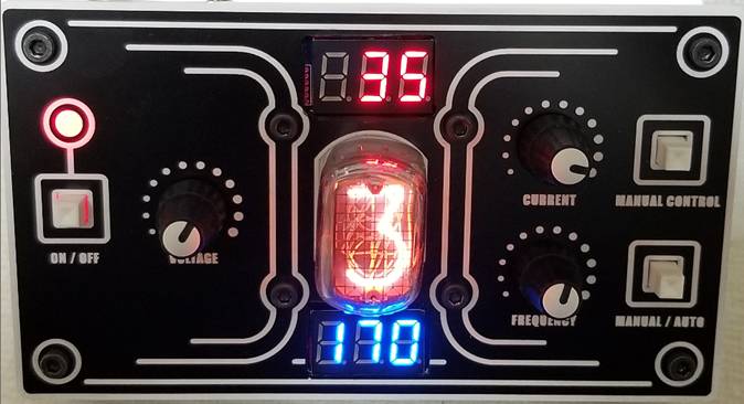
Little digital meters are inexpensive from eBay or other sources. Voltage requires no thinking. The current meter took a little more work and required a different shunt resistor to adjust from 1000mA to 100mA. Can’t control the decimal but could just use a marker to cover the dots if it bothers anyone. This is much more convenient than having to wire external meters. You could do this with any tester (if space allows).
Jeff
--
You received this message because you are subscribed to the Google Groups "neonixie-l" group.
To unsubscribe from this group and stop receiving emails from it, send an email to neonixie-l+...@googlegroups.com.
To post to this group, send email to neoni...@googlegroups.com.
To view this discussion on the web, visit https://groups.google.com/d/msgid/neonixie-l/5bfadcdc-bd85-4c01-8978-1c43cd5ad646%40googlegroups.com.
For more options, visit https://groups.google.com/d/optout.

gregebert
Peter H
Marcin Saj
Class of ammeter is fine but 2.5 for voltmeter with 200V range is moot.
Anyway analog meters are better suited to the nixie tubes.


Robert L
OK... I'll play...
Volt meter is downstream of the re-purposed current test toggle switch. Meter now reads the HV supply output voltage or the tube anode voltage depending on the position of the switch.
Current control is by an active current limiter... Current will stay constant (or be limited) if a tube heals while running. First image below shows the meters reading 2.8 mA tube current with the HV supply at 170 VDC. The tube below sustains glow at 139 VDC downstream of the limiter circuit as shown on the second photo... button caps were put back on switches after these photos were taken. Meter holes cut with the vertical mill at work, squared off with a small file. PCB SMD reflow was lead free with a Whizoo reflow toaster oven. Power supply needs addressed with a +12 VDC to +/- 5 VDC floating output switching supply module at the lower right of the pcb.


