Constant current regulator for Nixies
241 views
Skip to first unread message

ZY
Aug 13, 2016, 8:45:22 PM8/13/16
to neonixie-l
Hello. I'm wondering if people typically use some sort of constant current regulator for their nixie clocks? Such as a simple LM317 current regulator at the anode instead of a current limiting resistor? I just started designing a circuit for some IN-18 tubes and since they were so expensive maybe some regulation circuitry would be worth it in the long run?
Do you guys also typically fuse each anode?

gregebert
Aug 14, 2016, 3:02:17 AM8/14/16
to neonixie-l
I use current-regulation on my nixie designs, and I've done cathode-side as well as anode-side regulation. Where you decide to regulate the current depends upon the driver you select. So far, all of my designs use direct-drive (non-multiplexed).
My 'Tomorrowland' clock uses HV5532 drivers (it has fourteen IN-18 tubes), so I regulate current on each anode. Yes, there are 14 current regulators.... My wristwatch uses NPN transistors to drive the cathodes, so I regulate the current on each segment.
Since 10mA fuses really aren't available, I size the resistor in the current-regulator so that it will operate at about 1/2 it's rated power during normal operation. For example, an 0805 SMT resistor is rated for 1/8 Watt, so I try to design for around 50-60mW. If a gross failure in the regulator occurs, the resistor should overheat and open. I have not tested it, though. I have a fuse on the power supply, and use the smallest value that will handle max operating current.
If you really want to be paranoid, monitor all of your anode currents with a multi-channel ADC. I've never done that, but it sounds like a fun project.
For cathode current-regulation, you would use an NPN or NMOS transistor; anode-side would use a PNP or PMOS. I found that high-voltage PMOS devices aren't nearly as common as NMOS.
If you use MOS devices, I'd recommend a zener-diode across gate-source and also very-high resistors (10Meg +) across drain-source to protect from ESD or unanticipated voltage spikes. It's probably overkill but SMT devices are so cheap and small it's worth the cost to me.
ZY
Aug 21, 2016, 6:09:31 AM8/21/16
to neonixie-l
What is your method of current regulation? For example, do you use a PnP transistor or the lm317 method, or something else? I have room to add something for my anodes, but I'm unsure if using a transistor would be accurate.
gregebert
Aug 21, 2016, 11:37:11 AM8/21/16
to neonixie-l
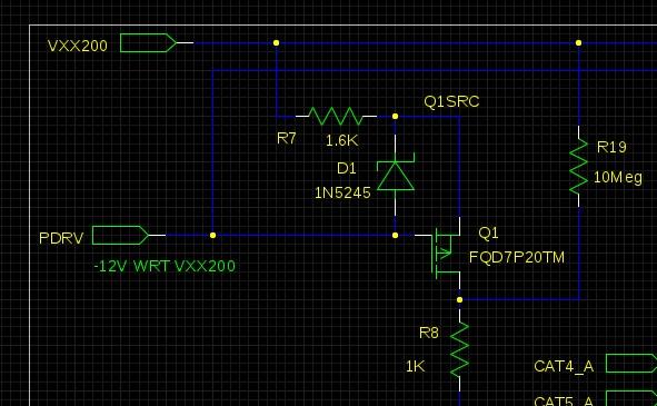
For anode-side, I use a PMOS device (see attached picture). The current is set to (PRDV-Vgs)/R7. You can get Vgs(on) from the datasheet, usually it's around 4V for higher-voltage PMOS devices. The PDRV signal generated from a potentiometer and a small 12V DC-DC converter; adjust it to obtain proper current..
The zener diode protects the gate-source from unexpected spikes. The 10meg resistor is for bleeding any ESD; the value isn't critical but I use the highest value SMT resistor I can get at low-cost. I'm being overly paranoid about voltage spikes and ESD because if the PMOS device is damaged it could fail later in time and damage the nixie. The resistor R8 is intended to act like a fuse, though R7 would likely burn out first. It will take about 20mA to do that, which is a lot more than the nixie tube is rated for, but at least it wont allow basically unlimited current.

jf...@my-deja.com
Aug 21, 2016, 3:14:24 PM8/21/16
to neonixie-l
On Saturday, August 13, 2016 at 5:45:22 PM UTC-7, ZY wrote:
...maybe some regulation circuitry would be worth it in the long run?
If you do this, you might want to modulate the current proportional to illuminated length of each character, so an 8 would draw more current than a 0 and much more than a 1. If these dimensions are not already in the spec sheet, you could measure them yourself.
gregebert
Aug 21, 2016, 3:53:14 PM8/21/16
to neonixie-l
Generally, the '1' is actually two parallel wires,so it's comparable in length to the other numerals.
Datasheets for segmented displays clearly show different currents for various segments, but I have not seen that for full-formed nixies (eg, 10 cathodes for 0-9)
Reply all
Reply to author
Forward
0 new messages