Lighting up a DM160

Paul Andrews

Dylan Distasio
I just impulsively bought some DM160 VFD indicators and now I am at a loss as to how to power them! Can anyone help?
--
You received this message because you are subscribed to the Google Groups "neonixie-l" group.
To unsubscribe from this group and stop receiving emails from it, send an email to neonixie-l+unsubscribe@googlegroups.com.
To post to this group, send email to neoni...@googlegroups.com.
To view this discussion on the web, visit https://groups.google.com/d/msgid/neonixie-l/234b6083-384b-42ba-a99a-a2ec08f043e7%40googlegroups.com.
For more options, visit https://groups.google.com/d/optout.
judg...@gmail.com
Thanks. That got me started finding some more info too. I might be back if I don’t get anywhere with the practicalities!
From: Dylan Distasio
Sent: Thursday, March 9, 2017 9:51 PM
To: neoni...@googlegroups.com
Subject: Re: [neonixie-l] Lighting up a DM160
Are you asking specifically about how to get the different required voltages in practice or what the voltages/current/pinouts are in the first place?
If the latter, this is a pretty well explained datasheet:
On Thu, Mar 9, 2017 at 9:32 PM, Paul Andrews <pa...@nixies.us> wrote:
I just impulsively bought some DM160 VFD indicators and now I am at a loss as to how to power them! Can anyone help?
--
You received this message because you are subscribed to the Google Groups "neonixie-l" group.
To unsubscribe from this group and stop receiving emails from it, send an email to neonixie-l+...@googlegroups.com.
To post to this group, send email to neoni...@googlegroups.com.
To view this discussion on the web, visit https://groups.google.com/d/msgid/neonixie-l/234b6083-384b-42ba-a99a-a2ec08f043e7%40googlegroups.com.
For more options, visit https://groups.google.com/d/optout.
--
You received this message because you are subscribed to a topic in the Google Groups "neonixie-l" group.
To unsubscribe from this topic, visit https://groups.google.com/d/topic/neonixie-l/JMUjZb3iSUY/unsubscribe.
To unsubscribe from this group and all its topics, send an email to neonixie-l+...@googlegroups.com.
To post to this group, send email to neoni...@googlegroups.com.
To view this discussion on the web, visit https://groups.google.com/d/msgid/neonixie-l/CAJrqPH_UitRR%2BHX%2BBepywGPEVioXShQHgKCOWcktS_rakqe3qQ%40mail.gmail.com.
Paul Andrews
Apologies if what follows seems impossibly naive. That's because it is!
It seems there is no getting away from driving the anode at 50V. I'm currently trying to figure out how I can do that given what I have on hand, before I order the parts I need to build an actual 50V supply. Basically buying a bunch of 9V batteries or making a simple voltage divider for one of my nixie power supplies.
I am a little concerned about limiting the current. Do I have to or will it just draw the current it needs?
I'm also slowly wrapping my head around -Ve voltages. I think I am gathering that the filament is held at a constant voltage and then you tweak the grid voltage to make it +Ve or -Ve with respect to that. Or maybe the other way around. I've not quite got that straight yet! Most of what I can find on the web wants to make oscillators or amplifiers or VU meters out of these. All of which sounds like fun, but right now I just want to light one up!
Dylan Distasio
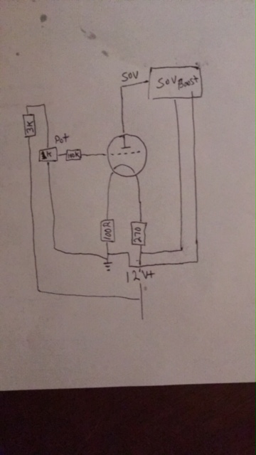
Finally I get it. If anyone is interested I will work on a schematic. I should probably do that for my own benefit anyway.
--
You received this message because you are subscribed to the Google Groups "neonixie-l" group.
To unsubscribe from this group and stop receiving emails from it, send an email to neonixie-l+unsubscribe@googlegroups.com.
To post to this group, send an email to neoni...@googlegroups.com.
To view this discussion on the web, visit https://groups.google.com/d/msgid/neonixie-l/a5736e41-4ae4-43cb-b125-e3cebec6874a%40googlegroups.com.

Manuel Azevedo
Thanks!

Roddy Scott
Paul Andrews
Manuel Azevedo
Thank you!
Paul Andrews

Tidak Ada
Look also for uranium glass stuff, especially marbles what are also good sources.
eric
--
You received this message because you are subscribed to the Google Groups "neonixie-l" group.
To unsubscribe from this group and stop receiving emails from it, send an email to neonixie-l+...@googlegroups.com.
To post to this group, send email to neoni...@googlegroups.com.
To view this discussion on the web, visit https://groups.google.com/d/msgid/neonixie-l/5d5cef0f-7c18-4934-a27a-e13ce284fd3a%40googlegroups.com.

Dekatron42

Nick
Nick

Thomas Kummer
Paul Andrews
--
You received this message because you are subscribed to a topic in the Google Groups "neonixie-l" group.
To unsubscribe from this topic, visit https://groups.google.com/d/topic/neonixie-l/JMUjZb3iSUY/unsubscribe.
To unsubscribe from this group and all its topics, send an email to neonixie-l+...@googlegroups.com.
To view this discussion on the web, visit https://groups.google.com/d/msgid/neonixie-l/3fbfc74c-6353-433a-b258-5d1fb8127fd3%40googlegroups.com.
Thomas Kummer
You received this message because you are subscribed to the Google Groups "neonixie-l" group.
To unsubscribe from this group and stop receiving emails from it, send an email to neonixie-l+...@googlegroups.com.
To view this discussion on the web, visit https://groups.google.com/d/msgid/neonixie-l/CABCPn3ijYYcSxQ9zGLcY6dQJVH5Q%3DEBUejp56A2kghO_xt1ouw%40mail.gmail.com.