Dekatron Experiments

threeneurons
Well, those who know me, know that I have attraction to dekatrons. Here's some of my latest tinkering. A long while back I designed a 4000 CMOS base pendulum circuit. It used a 4017 counter, and a 4013 flip-flop. I revisited that circuit, and came up with one that just uses on 4518 dual counter:

In addition to the one chip, and the HV interfacing transistors, there's a clever little piece of what Don Lancaster referred to as "Mickey Mouse logic". The one transistor and its associated components, in the pink field, form an exclusive-OR gate. Half the chip along with XOR ckt, make the guide timing circuit. The other half of the chip is used as the direction flip-flop. Circuits quite nicely. HV supplies, and clock, not shown.
In my test circuit, I decided to run two dekatrons. One master, and one slave. To align the slave tube, I added a reset circuit to K0 (normally used as the NDX). This forces the glow to K0, instantly. Here's that portion of the circuit:
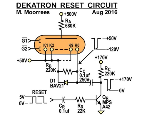
I hooked it such that when QD (pin 14), of the IC went high, the reset was issued. That meant a reset every 10 'flips'.
It worked ... mostly. I noticed something strange. If I used a A101 as a slave, the glow reset to K0, as expected. But using several 6802's and a GC10B, the glow appeared to reset to K9. After some poking around, I decided to check the reset, with the guides (G1 & G2) off. Then, indifferent to tube type, the reset forced to glow to K0. So this new pendulum circuit "backsteps" some tubes from K0 to K9, almost instantly.
Here's a photo of the test circuit, and video of it running:

Video of above circuit.
Enjoy

Dekatron42

Nick
threeneurons
threeneurons
threeneurons
Yeah. I saw the odd voltage levels too!

Keith Moore

John Rehwinkel
- John
threeneurons
On Wednesday, August 17, 2016 at 2:19:55 PM UTC-7, Keith Moore wrote:
OMG! That 0A5 arc discharge dekatron spinner is amazing, too!

One of the destructively cool things about this circuit, is how it continuously popped carbon film resistors in the R6 location. There, current pulses greater than 5 amps, would pass thru. A hole would be punched right thru the outer coating of the victimized resistor. I had to replace it with a wirewound, for reliable operation.