Active cooling for Replicator 2x

Miguel Alvarez

David Celento
The question that is open relates to fan electrical load and if the motherboard can/will handle this. Loads are light, but care is advised. There is a thread on this topic in the new 3d Tips and Tricks group.
I should add that MBI warns that meddling may make it harder to diagnose issues.

Laird Popkin

Dan Ujvari
--
You received this message because you are subscribed to the Google Groups "MakerBot Operators" group.
To unsubscribe from this group and stop receiving emails from it, send an email to makerbot+u...@googlegroups.com.
For more options, visit https://groups.google.com/groups/opt_out.
Miguel Alvarez
David, could you give me a link to this thread? Also, I have taken the load considerations. I was thinking of maybe using the output on the board to trigger a relay for the fans using an external power supply. Im assuming the fan port activates automatically when I choose PLA as the printing material in makerware. I also ordered 2 12v fans of the same dimensions accidently before realizing the bot runs 24v (thing o matic is 12v and i made assumptions). I could probably run these two fans in series with 1 port. I'll have to test the current and everything though to make sure it doesnt draw too much.
Dan and Laird,
Great suggestion, I actually used something like this on my thing o matic and it does work great. However when I pay $2800 for a machine and it has an extra port for an automatically controlled fan with better/colder airflow, I dont want to settle for less. An extra $30 at this point doesnt hurt. If this fails though, I will probably end up resorting this
> To unsubscribe from this topic, visit https://groups.google.com/d/topic/makerbot/d6R9Rm_QTqc/unsubscribe?hl=en-US.
> To unsubscribe from this group and all its topics, send an email to makerbot+u...@googlegroups.com.

Eighty
I would assume so, but you probably want to make sure the profile includes DoFanCommand=true, then confirm the gcode. You'll be looking for the M126 T0 command after the 3rd layer.
David Celento
|
Miguel Alvarez
Miguel Alvarez
Eighty
Skeinforge will have it in the start.gcode, and it may not exist for the R2X version. But it's pretty east to add. Or add it manually in your sliced gcode after layer 3, if you'd like.
Miguel Alvarez
David Celento
Miguel Alvarez
David Celento
Eighty
If you artsy architect types took any courses in Electrical Engineering, you'd understand how two 12V fans in series can run on 24V...:-)
Miguel Alvarez

Dan Newman
On 13 Apr 2013 , at 11:25 AM, Eighty wrote:
> Miguel,
> Skeinforge will have it in the start.gcode, and it may not exist for the R2X version.
hasn't as I expect they have no intention of release another version of RepG.
Jetty and I do not have a Rep 2X to test on making it awkward. My guess is
that the Rep 1 Dual profiles but changed for Rep 2X dimensions would be what
would work best. I'll put it on the to do list but would need someone to test
them….
Dan
Eighty
Man, this is fun. I could do this all day!
David Celento
On Apr 13, 2013, at 8:10 PM, Eighty wrote:
> Architects work much better with abstracts. Details just confuse them.
> Man, this is fun. I could do this all day!
>
Eighty
David Celento
Given that Architectural licensure requires structural analysis and calculations, I know more Architects who have Engineering skills than Engineers who have Architectural skills. ;-P
(it never gets old, does it?...)
On Apr 13, 2013, at 10:14 PM, Eighty wrote:
> Couldn't help myself. I spent 10 hours today in a committee meeting full of engineers, updating ACI specifications. Committees drive me insane, but I was glad that we could agree on at least one point: The term "Engineer/Architect" is preferable to "Architect/Engineer".
>

David Kessner
Miguel Alvarez
David Celento
Don't run the fans in series. At best, it won't work as you expect. At worse, you'll fry the fans and maybe your bot.

Joseph Chiu
David Kessner
Miguel Alvarez

PhGeis
Philips
Miguel Alvarez
Dan Newman
On 14 Apr 2013 , at 3:42 PM, Miguel Alvarez wrote:
> Dan I'd be willing to test for you. Its the least I could do for the
> improved thing o matic :P, but I have to say I wont be very free until
> after my finals which will be around May 8th. If you'd like I could give
> you my email and we can discuss this separately
Rep 2X profiles in RepG 40rX - Sailfish. I simply forgot that we
had put them in…. And, I've been told that they are working.
Dan
Miguel Alvarez
Miguel Alvarez
I agree they're not hard to use,
but as some people have pointed out, they're not 100% energy efficient and dissipate heat. If this can be avoided it makes the setup much simpler and easier for others without electronic experience.
On Sunday, April 14, 2013, Damian Gto <dami...@gmail.com> wrote:
> Just use a voltage regulator and reduce the volt to what ever volt the fan needs. Its very easy to use and it more safe for the bot.
> Choose the one that can handle about 30 volt in and reduce it to what you want. They are very cheap and very safe to use.
Joseph Chiu
Well use 24v fans. thats the only simple way ;-)To use 12v fan you need to reduce the volt to 12v.The simple way for this is to use a voltage regulator, if you want to rep to be able to control it.A more simple way is to use external power to it.More advanced way is to build a circuit that will use external power, but use the onboard control for the fan to switch it on/of or make it with a thermostatic switch that will turn on the fan when it needs to.But none of this is simple, more then use the right volt on the fan, for the normal user. I can make this without problem, but I have that skill :-P
--
You received this message because you are subscribed to the Google Groups "MakerBot Operators" group.
To unsubscribe from this group and stop receiving emails from it, send an email to makerbot+u...@googlegroups.com.
Miguel Alvarez
On Monday, April 15, 2013 10:49:50 AM UTC-5, Damian Gto wrote:
Well use 24v fans. thats the only simple way ;-)To use 12v fan you need to reduce the volt to 12v.The simple way for this is to use a voltage regulator, if you want to rep to be able to control it.A more simple way is to use external power to it.More advanced way is to build a circuit that will use external power, but use the onboard control for the fan to switch it on/of or make it with a thermostatic switch that will turn on the fan when it needs to.But none of this is simple, more then use the right volt on the fan, for the normal user. I can make this without problem, but I have that skill :-P
On Monday, April 15, 2013 5:38:17 PM UTC+2, Miguel Alvarez wrote:

Count Spatula
David Kessner
Miguel Alvarez
Miguel Alvarez
On Friday, April 12, 2013 12:38:21 PM UTC-5, Miguel Alvarez wrote:
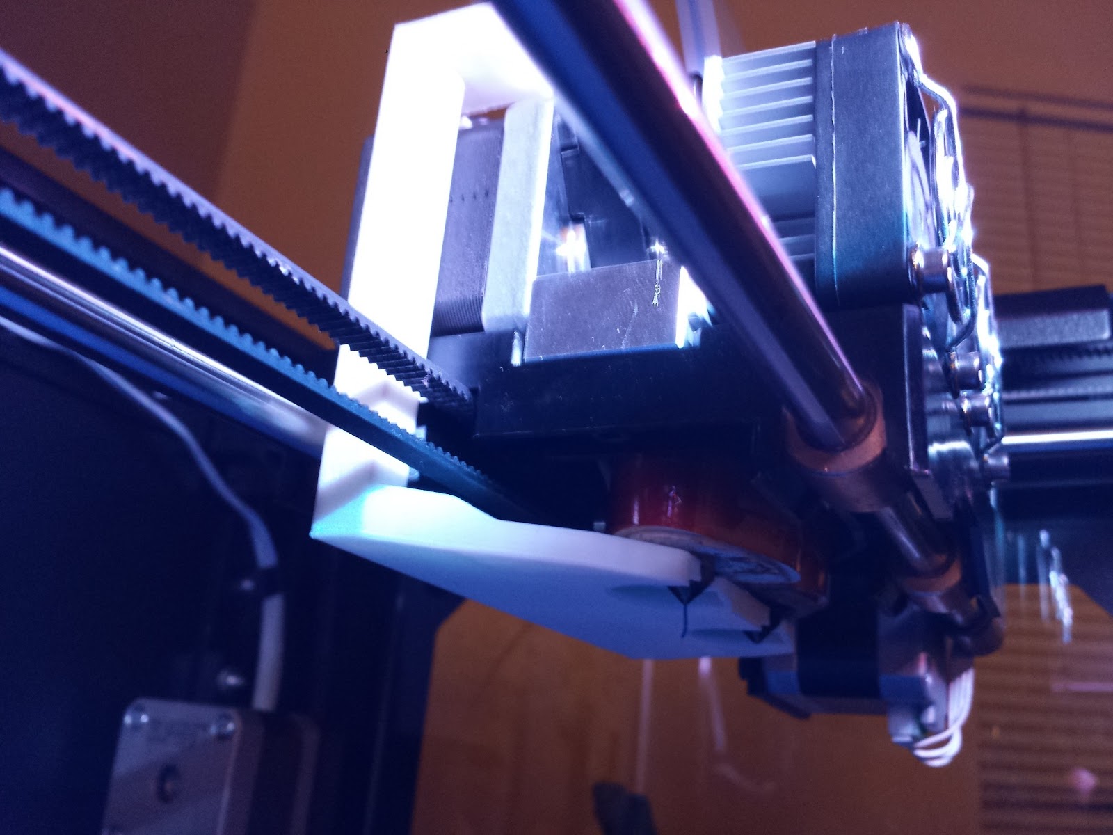
When I got ordered the replicator 2x, my main interest wasn't to be able to print with ABS but to be flexible in general with using different materials and also being able to dual extrude to use PVA as support. That being said I still like printing PLA in general because of the reduced warping and start up speed (platform doesn't have to be heated).Since the 2X doesnt include an active cooling fan, I decided one of the things I want to do is install my own. This is what I know so far from searching around.The replicator 2X motherboard has an unused connection which is what the replicator 2 uses for the active cooling fan.This image was provided by Kobus du Toit in another thread showing the open portAfter going through some of the replicator 2x documentation. I found this under the "menus" link in their documentation page"The Filament Fan setting allows you to turn an active cooling fan on and off during a build. Your Replicator 2X does not come with an active cooling fan installed."This leads me to assume that the replicator 2X allows control of an active cooling fan if it were connected to this open portI found the model of the active cooling fan from a video of somebody removing it from the replicator 2. http://www.youtube.com/watch?v=shv-ssIgQFYHere is a digikey link to the part number for the fan which I'll be ordering soon.This I believe is the proper connector for the motherboards fan connectionOnce I get some parts in I will test things out and eventually design a mount to attach the fan. Thought I'd post this for other people that might be interested in doing the same.Miguel Alvarez
David Celento
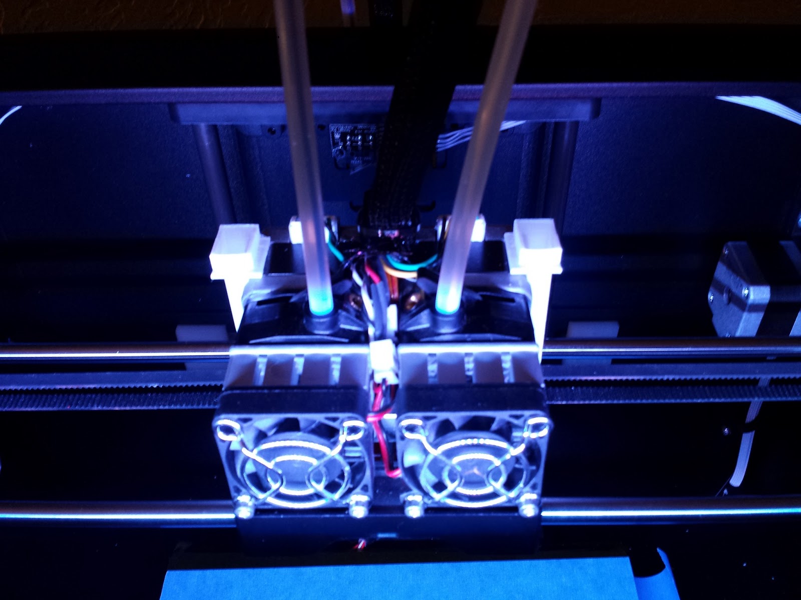
Have you decided where to mount them?
~Dave
Miguel Alvarez
Miguel Alvarez

David Celento
Miguel Alvarez

Jake
On the 3rd picture, the rectangles on the right and left side are the fan slots. Sorry I didnt include the fans in the picture, that probabpy wouldve made it clearer.
Miguel Alvarez
Jake
I've been eyeing these as a potential solution for a compact solution, but I haven't started any real work on designing anything:

camstuff
Miguel Alvarez
Miguel Alvarez
Miguel
PhGeis
Miguel Alvarez
As of right now Ive tried connecting both fans from the original post in parallel without any other components. The parts from the original post including the connector are all correct. The only problem I have is that when the fan isnt set to be on, the fan port outputs 18v so turning the fan on and off from the settings just changes the speed, but its always on. Ive had nobody else confirm this for me on their bot and Im thinking it might be a defect on my board
PhGeis
Philipp
Miguel Alvarez
Its labeled on the board and its the only connector. You'll see it but if you dont I can get you the picture. Also I hope you didnt forget to include the connector crimps. I didnt include them with the rest of the links since the link for those is provided in the product page
camstuff
Miguel Alvarez
Miguel Alvarez
PhGeis
Miguel Alvarez
I could add a slot or extra arm that would provide cooling to the plastic. The only problem is that this might reduce printing space. The heat creep problem seems to depend on the temparature of the area where you're printing. I did not have the problem (Printer is in my room) but I have a friend that did with his rep 2. His printer was set up in his garage (no AC). I told him to try it in his room and it fixed the problem. Anyway, I'll try to add an extra slot when I have time (let me know if you need it a specific aize), I'm also worried though that this might greatly reduce the output air flow on the extruder tip considering its not that high at the moment.
Miguel

Eric Weber
PhGeis
Miguel Alvarez
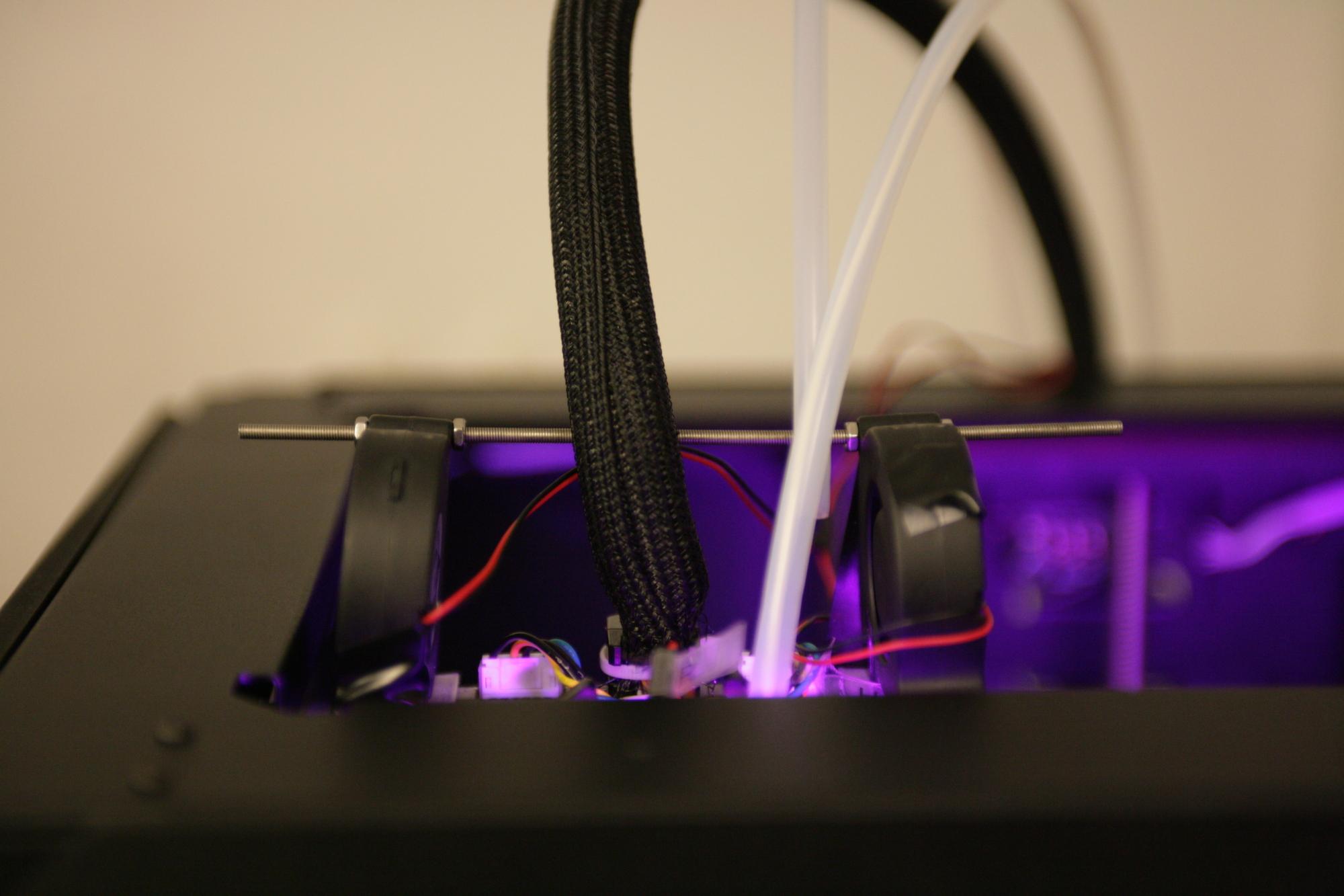
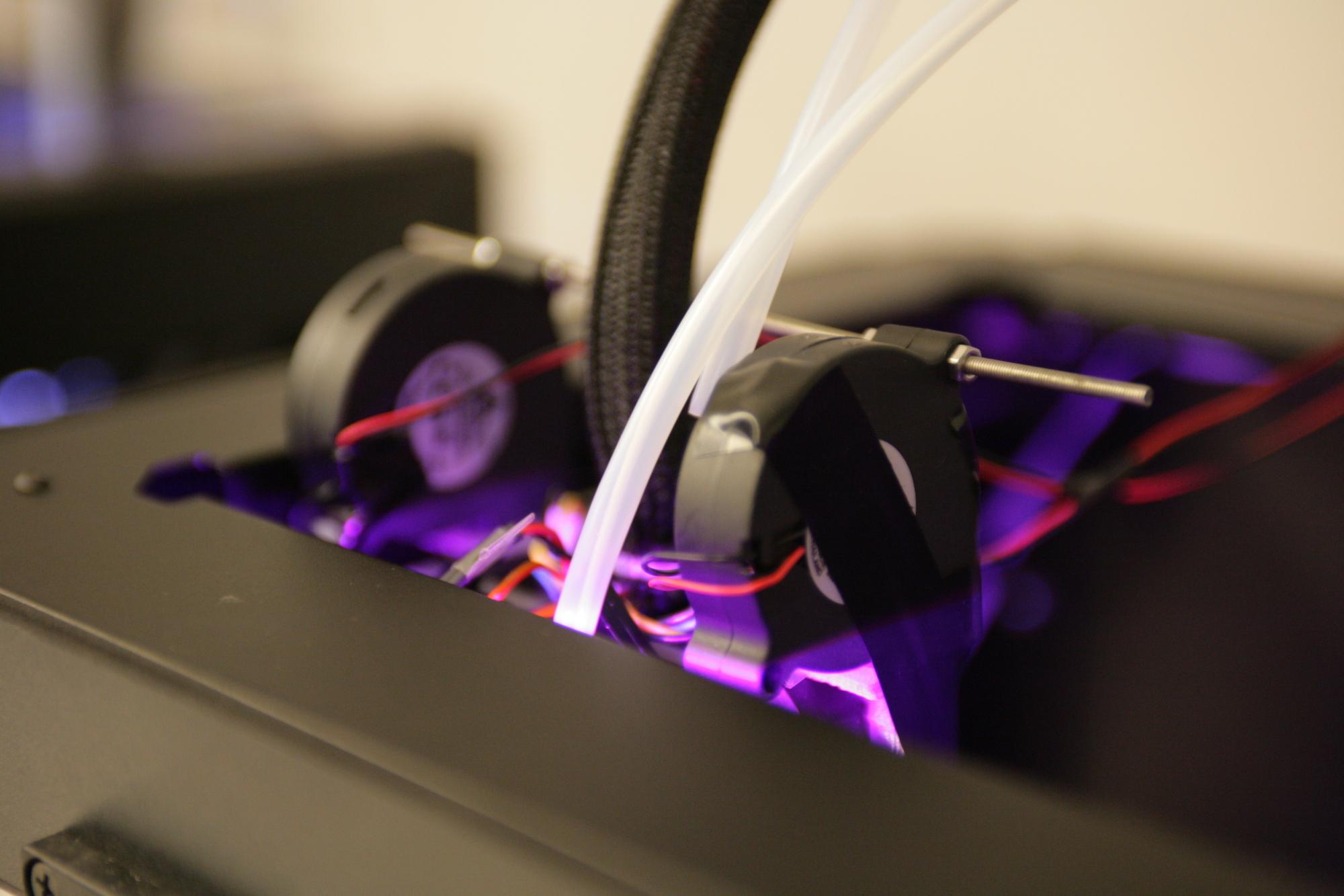
Thought I'd give an update for those of you wondering whats going on.
Eric Weber
Thanks for the update. I just received the fans and plan to print the prototype during the week.
--
You received this message because you are subscribed to a topic in the Google Groups "MakerBot Operators" group.
To unsubscribe from this topic, visit https://groups.google.com/d/topic/makerbot/d6R9Rm_QTqc/unsubscribe?hl=en-US.
To unsubscribe from this group and all its topics, send an email to makerbot+u...@googlegroups.com.
For more options, visit https://groups.google.com/groups/opt_out.

Jake Dambergs
Miguel Alvarez

Jetguy
Jake Dambergs
Miguel Alvarez
Jetguy
Miguel Alvarez

TaErog
"BTW this is why EV (Electric Vehicles) have a huge problem. You think Toyota had it bad with uncontrolled acceleration" -Jetguy
To date there is no cases of a uncontrolled acceleration in a production model EV (if there is and you have real documentation send it along). All of the Toyota uncontrolled acceleration problems where with "normal" cars and due to mechanical problems (+1 at least, electrical). The only Prius recall had to do with the breaks (a uncontrolled deceleration problem :) really) re-tuned anti-lock brakes fixed this (this has been a more or less common anti-lock break problem across car lines/makes) for some reason people think/feel acceleration but it is not. This has been researched to death and found that people where breaking at the time and slowing - just not as fast and smoothly as wanted, the strange studder felt to some as acceleration and had caused a few crashes. Other cases where all out fraud and even prosecuted.
Also, real uncontrolled acceleration in other makes again tended to be mechanical problems or mats (ie Ford etc ), though a few had throttle problems (ie Honda etc) and at least one a short circuit (Camry)
Sorry, after researching this to a great extent to see what was up, (I may have been effected) I found the controversy was almost all news drama with some real but few true problems, nothing to ignore but blown way out of proportion..
Back to the scheduled program:
I am working on just a quick attach blower fan with just a simple 12v wall power-supply, to cool the block and plastic . . . I do not think there is much need for MB control. I might even add a fan control to vary the speed - whatever I can find in my PC MOD leftovers, and a printed duct? . Should be simple and effective. Not crazy hot plugging more into that board. Though I would be interested in how things go.

Bottleworks
On the Mightyboard fan FETs.... I had one fail for my heatsink fan (rep 2). They are finally sending me a replacement Mightyboard. It took a long time for the tech to understand what's going on. I think I was giving too much data at once.
Jetguy
| |||
Re: Run away EV
PS. I had a curtis go about 9 years ago. I was still
new to ev's so it had the controler right behind the drivers seat. Luckly I
lived and learned. Anyway I can't remember slaping it in neutral
but I was out and on the pavement fast. Second luck was it happened in my drive
way. Lots more details than any of you want to hear. Third luck was I have over
speed control so as soon as I collected my wits I hade time to climb back in and
shut it down. Whats it like you ask? BIG BOOM!!! Lots and lots of smoke. FETS are known to fail shorted in almost every industry. The causes are known and so are the protection methods. So the problem is the Replicator 2X folks asked if they could just plug in a fan to the motherboard. The problem is, the mightyboard rev E used in the Replicator 2 and 2X is NOT open source. This means that of the several certified engineers poking around in the forums, NONE of us can verify the schematic for best pratices, specifications, layout problems etc.. MakerBot will not provide information on specs or rating either. So again, the question was asked can we just plug fan into the motherboard. Rather than just say yes, us engineers KNEW we cannot say yes to that question because we have no idea what the capabilities for current are for that port. We could not verify if a diode was in place. Fans are motors made of coils of wires also known as inductors. Inductors produce a voltage spike each time they are turned off. If you PWM (Pulse Width Modulate) you effectively turn on and off the inductor rapidly and create huge amounts of voltage spikes at the FETs. So, someone did attach a fan and based on the assumption it would just work, blew the FET. Then, there is one other report of the same FET blowing. All I'm trying to relate is that FETS are known to blow when pushed out of spec or by inductive loads. We do not know how much the baord can take and MakerBot will not tell us. Even plugging in the exact same model of fan used on the Replicator 2 could be risky. The point is, there are proven failures and therefore this thread and failures should urge folks not to randomly go attaching any willy nilly fan to the port as it could cause the FET to fail. If you want to use a fan, you probably should power it externally or build a suitable opto isolated drive circuit. Note, in that circuit, they used a 330 Ohm resistor to limit current in the LED portion of the opto-isolator. You would need to adjust that up to a larger value for the 24 volts the mainboard supplies. I'm thinking a 1.8 k resistor is correct. The original circuit assumed 5 volt on the logic input side so 5V / 330Ohms is 0.015A, 24 volts / 1,800 Ohms is 0.0133A. That way, you are properly limiting the current through the LED section of the opto isolator to nearly the same current at before (slightly less for a margin of error). Of note in that circuit, it does show a proper diode on the FET for protection of the output. You could also add a similiar diode to the output on the board now, but it requires you to make sure it's installed the correct direction as incorrectly installed it would short the MOSFET and likely blow it. Basically, we re back to unknowns. I'd love to show you pictures and a mod to add such protection but I cannot verify the schematic and therefore cannot tell you correct direction on those pins. Further, I don't know what FET is used and there appears to be no properly rated fuse or overcurrent protection other than the main fuse which is just an "ah crap" function. Therefore, I have show legitimate reasons not to just willy nilly plug in any fan off the shelf, evne one you think will work or someone else said it worked. The risk to blowing the FET seems rather high.
|

Damian Gto
On Friday, April 12, 2013 7:38:21 PM UTC+2, Miguel Alvarez wrote:
When I got ordered the replicator 2x, my main interest wasn't to be able to print with ABS but to be flexible in general with using different materials and also being able to dual extrude to use PVA as support. That being said I still like printing PLA in general because of the reduced warping and start up speed (platform doesn't have to be heated).Since the 2X doesnt include an active cooling fan, I decided one of the things I want to do is install my own. This is what I know so far from searching around.The replicator 2X motherboard has an unused connection which is what the replicator 2 uses for the active cooling fan.This image was provided by Kobus du Toit in another thread showing the open portAfter going through some of the replicator 2x documentation. I found this under the "menus" link in their documentation page"The Filament Fan setting allows you to turn an active cooling fan on and off during a build. Your Replicator 2X does not come with an active cooling fan installed."This leads me to assume that the replicator 2X allows control of an active cooling fan if it were connected to this open portI found the model of the active cooling fan from a video of somebody removing it from the replicator 2. http://www.youtube.com/watch?v=shv-ssIgQFYHere is a digikey link to the part number for the fan which I'll be ordering soon.This I believe is the proper connector for the motherboards fan connectionOnce I get some parts in I will test things out and eventually design a mount to attach the fan. Thought I'd post this for other people that might be interested in doing the same.Miguel Alvarez
Jetguy
Jetguy
On Friday, June 14, 2013 8:50:16 AM UTC-4, Damian Gto wrote:
TaErog
"he Zinc wiskers thing was real and did get recalled."-jetguy
Yup that was the Camry I listed (just said a short because most people would understand that - and it effectively was) and yes it did cause the problem. No argument there. But again it was not part of the big recall people rave about, was not very far reaching, more of a manufacturing flaw that was not uncommon at the time and not a FET failure.
Also I would say hybrid's could fit into that category as they do have completely electric driveling modes and thus similar hardware/electronics.
"True" EV are rare and sure allot of home made . . . so in these these DIY EVs flaws should be abundant. again no argument there.
"So, someone did attach a fan and based on the assumption it would just work, blew the FET. Then, there is one other report of the same FET blowing. All I'm trying to relate is that FETS are known to blow when pushed out of spec or by inductive loads. We do not know how much the baord can take and MakerBot will not tell us. Even plugging in the exact same model of fan used on the Replicator 2 could be risky. The point is, there are proven failures and therefore this thread and failures should urge folks not to randomly go attaching any willy nilly fan to the port as it could cause the FET to fail." -notmrwizard?
Interesting . . I would be quite interested in continued information.
I did make today the blower out of a NMB BG0903-B044-00S (12v) Got a 1 of many wall transformers to try it on and found the one that fits the specs - and massive overkill that fan is powerful! Found a 7v transformer and that was much better. (though need to check the draw) or find my 12v fan controller. Need to make a clip for it (placing it on the back of the case near the filament feed) . . BUT lost the back tubing I was going to use!! off to the store later! Prototype is rather crude but gets the air where I want it. and benefit is it is removable and uses a separate power supply!
Any ideas on a 2x duct for cooling the filament I could mod? do not want to reinvent the wheel here if I do not have to?
TaErog
I do have issue on this statement though
" MakerBot doesn't want you to reverse engineer the board, otherwise they would publish info on it." - jetguy
I think you assume too much here. there are a host of good and rather mundane reasons not to publish info on the board that have nothing to do with purposely stopping customers from "reverse engineering the board".
I am not saying again that you are wrong here (it could be the or even a reason) but your strong opinion/assumption comes out as a absolute statement that in turn you also use as a basis for other opinions/assumptions. All of which begs the question are these opinions/assumptions even correct? on which you tend to be quite militant on insisting they are all absolutely correct even when sometimes valid conflicting information or views are expressed. and then you/them find the resulting conversation annoying . . things get heated . .
I for one am not going to plug in a fan to the MB before I get more information! on this we agree fully, but also I do not think it is imposable to figure it out or even wrangle it from MBI. personally I am just bypassing the issue for now. (to get this desk fan off my table) when printing PLA . . unfortunately it is going to be just as noisy . .
Miguel Alvarez
Jake Dambergs
Jake Dambergs > www.lptechsupport.ca
--
You received this message because you are subscribed to a topic in the Google Groups "MakerBot Operators" group.
To unsubscribe from this topic, visit https://groups.google.com/d/topic/makerbot/d6R9Rm_QTqc/unsubscribe.
Damian Gto
Eighty
Damian Gto
TaErog

Jeremy deGuzman
Miguel Alvarez
Miguel

David Schwartz

furicks

Jakob Öhman
PhGeis
Jakob Öhman
"doFanCommand": true,"fanLayer": 1,

"doFanModulation": true,
"fanModulationThreshold": 0.5,"fanModulationWindow": 0.1,Jetguy
Jakob Öhman
M126 T0; fan on
...
M127 T0; fan off
