Published proof of concept for new ratchet design...
154 views
Skip to first unread message

Mathieu Glachant
Feb 12, 2012, 2:31:50 PM2/12/12
to makerbot-c...@googlegroups.com
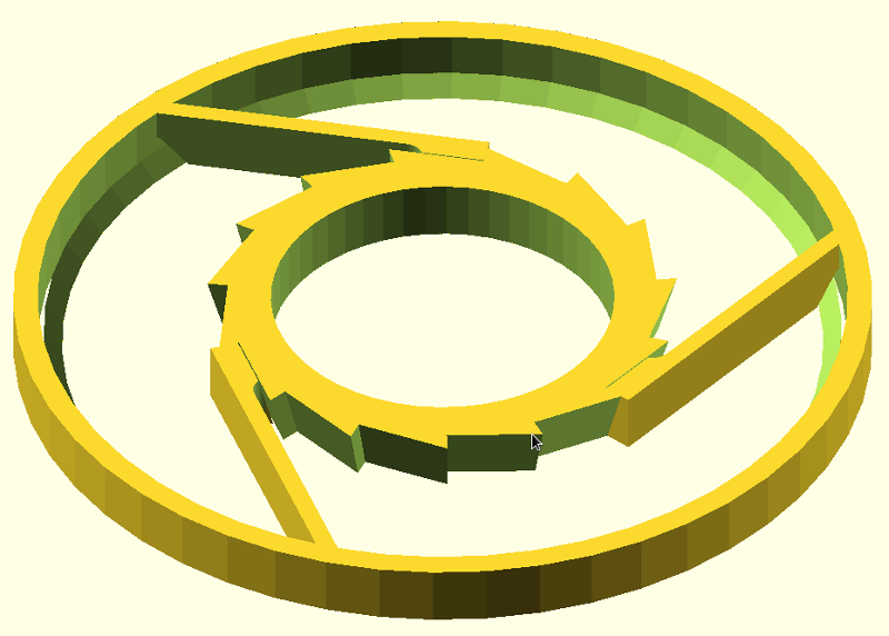
I just published a derivative of RustedRobot's fine ratchet design, which is intended to improve the axial load bearing capabilities, removing the need for a complicated and thick part with spokes that reach over the inner ring to reach the shaft.
http://www.thingiverse.com/thing:17458
It works (hopefully, anyway) by having the outer ring resting directly on the inner one, with the ratchet arms only needing to stop the rotation, not carry the axial load which is now transmitted directly, ring to ring. This should allow us to integrate a ratcheting drum into any wheel without breaking the connection between large gear and pinion gear, adding more thickness than the minimum needed for the string, or connecting the drum externally via some sort of physical API.
Plus, it's even prettier than the original ratchet, possibly. :-)

ruste...@prototribe.net
Feb 12, 2012, 3:48:20 PM2/12/12
to makerbot-c...@googlegroups.com
Neat idea!
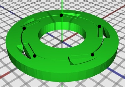
It looks like you're going to run into issues with the ratchet arm flex. The inner wheel begins applying its force at the bottom of the arm, meaning that it will need to do all its flexing right there at the base of the arm as opposed to being able to flex across the entire arm. You could possibly undercut the ratchet arms a bit or possibly even punch a circle at the base of the arm on the side towards the center of the circle (see the black dots in the pic below). That may introduce enough flexibility into the arm.

Alternately either increasing or thickening the total number of arms or taking a two tier approach should increase the axial load bearing capabilities. Though in both cases the ratcheting will become more difficult.

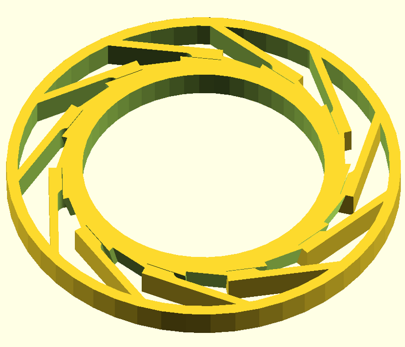
Here's a quick sample of breaking things into two tiers. Note, you can't really see it, but the arms are separated from the green disc by about 0.5mm in this picture. It emulates what you've got in one tier, while maintaining a high ratchet teeth ratio. The print is trickier and would need to be done upside down (with the arms on the build surface) and with support material. There are many variants of this with the bottom disc having various parts cut-out or even possibly replaced with triangular arms, etc...

I noticed that the ratchet drum you're using seems to be based on the mcad gears lib and the teeth are sparse with the ratchet arm faces not being in full contact with the ratchet wheel when bearing load. I believe this may make a difference in the load bearing capabilities as well.
Hope it helps!
Rustedrobot
It looks like you're going to run into issues with the ratchet arm flex. The inner wheel begins applying its force at the bottom of the arm, meaning that it will need to do all its flexing right there at the base of the arm as opposed to being able to flex across the entire arm. You could possibly undercut the ratchet arms a bit or possibly even punch a circle at the base of the arm on the side towards the center of the circle (see the black dots in the pic below). That may introduce enough flexibility into the arm.
Alternately either increasing or thickening the total number of arms or taking a two tier approach should increase the axial load bearing capabilities. Though in both cases the ratcheting will become more difficult.
Here's a quick sample of breaking things into two tiers. Note, you can't really see it, but the arms are separated from the green disc by about 0.5mm in this picture. It emulates what you've got in one tier, while maintaining a high ratchet teeth ratio. The print is trickier and would need to be done upside down (with the arms on the build surface) and with support material. There are many variants of this with the bottom disc having various parts cut-out or even possibly replaced with triangular arms, etc...
I noticed that the ratchet drum you're using seems to be based on the mcad gears lib and the teeth are sparse with the ratchet arm faces not being in full contact with the ratchet wheel when bearing load. I believe this may make a difference in the load bearing capabilities as well.
Hope it helps!
Rustedrobot
ruste...@prototribe.net
Feb 12, 2012, 3:53:28 PM2/12/12
to makerbot-c...@googlegroups.com
I forgot to mention, if you get this to a state you're happy with let me
know and i'll roll it into the ratchet lib.
know and i'll roll it into the ratchet lib.
Rustedrobot
On 02/12/2012 02:31 PM, Mathieu Glachant wrote:
Mathieu Glachant
Feb 12, 2012, 4:13:47 PM2/12/12
to makerbot-c...@googlegroups.com
We had one of the ratchet drums collapse during clockathon #2... But that took some ridiculous weight.
My main motivation here is to make it fit in the smallest distance along the shaft possible, so I didn't want to use a two tiered approach... And any setup where the axial load is acting on the arms in exactly the same way as the allowed rotation is going to be limited.
I think the best way to do this is figure out a way to let the arms bend out of the way, but keeping as much ring to ring contact as possible. Could be as simple as a notch cut just before the arm, where you indicated with the black dots.
On Sunday, February 12, 2012, <ruste...@prototribe.net> wrote:
> Neat idea!
>
> It looks like you're going to run into issues with the ratchet arm flex. The inner wheel begins applying its force at the bottom of the arm, meaning that it will need to do all its flexing right there at the base of the arm as opposed to being able to flex across the entire arm. You could possibly undercut the ratchet arms a bit or possibly even punch a circle at the base of the arm on the side towards the center of the circle (see the black dots in the pic below). That may introduce enough flexibility into the arm.
> </mail/u/0/s/?view=att&th=1357352f17995afe&attid=0.1&disp=emb&zw>
>
> Alternately either increasing or thickening the total number of arms or taking a two tier approach should increase the axial load bearing capabilities. Though in both cases the ratcheting will become more difficult.
> </mail/u/0/s/?view=att&th=1357352f17995afe&attid=0.2&disp=emb&zw>
>
> Here's a quick sample of breaking things into two tiers. Note, you can't really see it, but the arms are separated from the green disc by about 0.5mm in this picture. It emulates what you've got in one tier, while maintaining a high ratchet teeth ratio. The print is trickier and would need to be done upside down (with the arms on the build surface) and with support material. There are many variants of this with the bottom disc having various parts cut-out or even possibly replaced with triangular arms, etc...
> </mail/u/0/s/?view=att&th=1357352f17995afe&attid=0.3&disp=emb&zw>
My main motivation here is to make it fit in the smallest distance along the shaft possible, so I didn't want to use a two tiered approach... And any setup where the axial load is acting on the arms in exactly the same way as the allowed rotation is going to be limited.
I think the best way to do this is figure out a way to let the arms bend out of the way, but keeping as much ring to ring contact as possible. Could be as simple as a notch cut just before the arm, where you indicated with the black dots.
On Sunday, February 12, 2012, <ruste...@prototribe.net> wrote:
> Neat idea!
>
> It looks like you're going to run into issues with the ratchet arm flex. The inner wheel begins applying its force at the bottom of the arm, meaning that it will need to do all its flexing right there at the base of the arm as opposed to being able to flex across the entire arm. You could possibly undercut the ratchet arms a bit or possibly even punch a circle at the base of the arm on the side towards the center of the circle (see the black dots in the pic below). That may introduce enough flexibility into the arm.
>
> Alternately either increasing or thickening the total number of arms or taking a two tier approach should increase the axial load bearing capabilities. Though in both cases the ratcheting will become more difficult.
>
> Here's a quick sample of breaking things into two tiers. Note, you can't really see it, but the arms are separated from the green disc by about 0.5mm in this picture. It emulates what you've got in one tier, while maintaining a high ratchet teeth ratio. The print is trickier and would need to be done upside down (with the arms on the build surface) and with support material. There are many variants of this with the bottom disc having various parts cut-out or even possibly replaced with triangular arms, etc...
ruste...@prototribe.net
Feb 12, 2012, 5:15:41 PM2/12/12
to makerbot-c...@googlegroups.com
I'd noticed that part with your design. The folded back arms
effectively become supports for the drum's rotation which is quite
clever. The trick will be getting enough repeatable flexibility in
there. Given that much of the load is being transferred to the new
structure, it may be possible to get away with thinner arms.
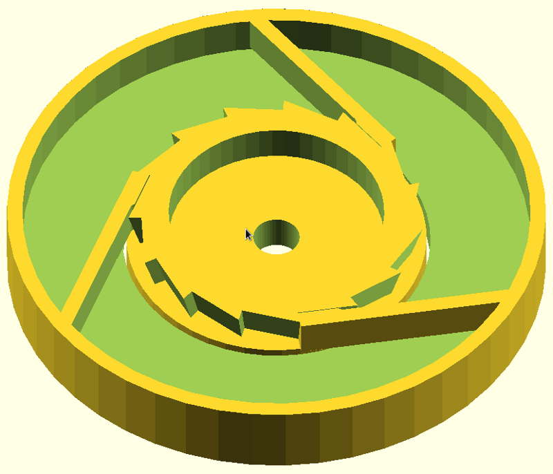
Here's another option:
There's a small lip with a triangular profile around the inside of the larger ring. It would attach to whatever gear is below. This should help take the load off that side of the drum, and the other end of the drum would typically be directly in contact an axle or nested shaft. The trick with this is making a substantial enough lip to take the needed weight without increasing the thickness too much.
Mathieu Glachant
Feb 12, 2012, 5:36:50 PM2/12/12
to makerbot-c...@googlegroups.com
Ok, I just realized what's going on. I've been saying axial when I meant radial. :"-> that's embarrassing!
The axial load is minimal in the clock, and jamming the gears together, possibly with some washers, is more than enough to keep everything in line, even without the herringbone gears.
It's the radial load from the weight on the string pressing the outer ring into the inner that I am worried about. If the arms are the only thing holding the outer ring away from the inner, and they are made to flex, it doesn't take much load to collapse them and have the outer ring fall onto the inner.
I posted a revised STL that looks like this:
http://www.thingiverse.com/image:108665
I think that should flex properly, or at least be adjustable until it does...
On Sunday, February 12, 2012, <ruste...@prototribe.net> wrote:
> I'd noticed that part with your design. The folded back arms effectively become supports for the drum's rotation which is quite clever. The trick will be getting enough repeatable flexibility in there. Given that much of the load is being transferred to the new structure, it may be possible to get away with thinner arms.
>
> Here's another option:
> </mail/u/0/s/?view=att&th=13573a2d9676cddf&attid=0.1&disp=emb&zw>
The axial load is minimal in the clock, and jamming the gears together, possibly with some washers, is more than enough to keep everything in line, even without the herringbone gears.
It's the radial load from the weight on the string pressing the outer ring into the inner that I am worried about. If the arms are the only thing holding the outer ring away from the inner, and they are made to flex, it doesn't take much load to collapse them and have the outer ring fall onto the inner.
I posted a revised STL that looks like this:
http://www.thingiverse.com/image:108665
I think that should flex properly, or at least be adjustable until it does...
On Sunday, February 12, 2012, <ruste...@prototribe.net> wrote:
> I'd noticed that part with your design. The folded back arms effectively become supports for the drum's rotation which is quite clever. The trick will be getting enough repeatable flexibility in there. Given that much of the load is being transferred to the new structure, it may be possible to get away with thinner arms.
>
> Here's another option:
ruste...@prototribe.net
Feb 12, 2012, 5:50:43 PM2/12/12
to makerbot-c...@googlegroups.com
Shame there wasn't video of it. I took a look back at your thing
here:
http://www.thingiverse.com/thing:17411
And am slightly confused as to there the loading is coming from. The drum itself is directly supported by the axle and bearings, same with the gear that interfaces with it. Am I missing something? Maybe the collapse was on an interim, unsupported drum that was part of the experiments?
In an unsupported drum, the arms are dealing with the radial load, but in the thing above all that load is being applied via the drum spokes directly against the axle. No?
Mathieu Glachant
Feb 12, 2012, 6:05:41 PM2/12/12
to makerbot-c...@googlegroups.com
So on the current design, we got arm failure by loading the drum with more than ten lbs. I think what happened is that the string was over the arms, and that was far out enough from where the hub on the shaft was to compress them unequally. In other words, the load wasn't being transmitted entirely as torque because the drum came out of alignment with the shaft, compressing the arms on one side. Does that make sense?
Now, for the new design I want of avoid the spokes altogether and have the drum resting directly on the collar between the large gear and the pinion of any of the wheels in the clock. It would slip on over the pinion, transfer the radial load into the hub of the wheel, which would be itself mounted on bearings, and be able to rotate without affecting either of the two gears on the wheel, so that rewinding the clock would not change the time.
For that, I would build the inner ring into the collar/spacer between large gear and pinion, and the outer ring would be on the inside of the drum.
Mathieu Glachant
Feb 13, 2012, 5:31:24 PM2/13/12
to makerbot-c...@googlegroups.com
Looks like you were totally right on the arms getting damaged if the inner rings hits them too close to their attachment point on the outer ring.
Surveyor printed the second design out, and posted a picture in the comments showing that the ABS whitened under the stress.
I'm going to have to add some more arm length, perhaps with a solid spur under it to provide support to the inner ring...
I'll doodle something on paper to show what I mean, since OpenSCAD doesn't run on this laptop.
Mathieu Glachant
Feb 19, 2012, 10:24:23 AM2/19/12
to makerbot-c...@googlegroups.com
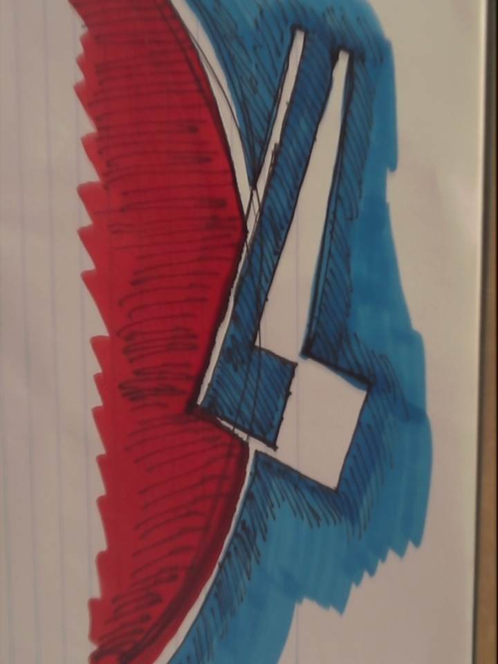
I doodled a lot on the ratchet design over the week and was hoping to have time to commit it to code over the weekend, but this is turning into a full blown working WE... So here is one of those doodles.
The basic idea is to move back the attachment point for the arm but provide a wedge under it to minimize the area where the outer and inner rings are not in direct contact.
This works best if the arm is at a fairly steep angle to the tangent, and perhaps the face where the arm butts up against the notch needs to be kept perpendicular to that same tangent. Alternatively, the arm could face the other way and instead of pushing against the inner ring, it could clip on with a hook.
Lastly, the gap left in the outer ring so the arm can bend out of the way could be gently curved so that the arm is never forced to bend sharply in a single spot.
ruste...@prototribe.net
Feb 19, 2012, 4:34:52 PM2/19/12
to makerbot-c...@googlegroups.com
Working weekends all around! Fortunately i'm in a printing phase so
not alot of time is required.
The one thing that occurrs to me with the ratchet sketch is the ratcheting head will move in an arc like fashion (not a pure arc given the arm will be flexing, but close enough) so the well may need adjusted a bit. I Iike how the head has depth so that when its fully compressed the head is resting against the outer ring adding to the support for the inner ring.
One other thing that occurred to me is the angle of the head engagement. I've run into a problem with my most recent drum prints in that the print had rounded the teeth and ratched heads enough that they can slip backwards with enough force. Making the engagement face a little angled so there is a positive engagement angle should help.
Current progress (doing center and right side first, will follow up with the left later):
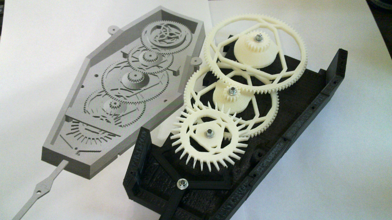
When finished it won't have concentric hands, but it looks like the screws are mounted firmly enough that I may be able to leave the face open which could be nice. Also the escapement wheel here is backwards and the panelization so far works great! I'll definitely have to make a library of it.
I'm contemplating adding rings that will attach to the minute and hour gears that have all the numbers printed on them with an indicator circle above that to help in identifying which hour/minute is currently selected.
Regards,
Rustedrobot
The one thing that occurrs to me with the ratchet sketch is the ratcheting head will move in an arc like fashion (not a pure arc given the arm will be flexing, but close enough) so the well may need adjusted a bit. I Iike how the head has depth so that when its fully compressed the head is resting against the outer ring adding to the support for the inner ring.
One other thing that occurred to me is the angle of the head engagement. I've run into a problem with my most recent drum prints in that the print had rounded the teeth and ratched heads enough that they can slip backwards with enough force. Making the engagement face a little angled so there is a positive engagement angle should help.
Current progress (doing center and right side first, will follow up with the left later):
When finished it won't have concentric hands, but it looks like the screws are mounted firmly enough that I may be able to leave the face open which could be nice. Also the escapement wheel here is backwards and the panelization so far works great! I'll definitely have to make a library of it.
I'm contemplating adding rings that will attach to the minute and hour gears that have all the numbers printed on them with an indicator circle above that to help in identifying which hour/minute is currently selected.
Regards,
Rustedrobot
Mathieu Glachant
Feb 19, 2012, 4:41:33 PM2/19/12
to makerbot-c...@googlegroups.com
That just looks amazing! I like both the idea of the printed numbers on a ring of the gear, and the idea of leaving the clock's coffin - err, case - open. Will the drum not need a little extra support in that case tho?
ruste...@prototribe.net
Feb 19, 2012, 5:04:51 PM2/19/12
to makerbot-c...@googlegroups.com
Need orange gears for Halloween! Not sure about the drum yet, I
haven't printed that far up! Although it has maybe 40mm of plastic
supporting the screw it will mount on. Hopefully i'll find out later
tonight! Also, I was originally envisioning the front panels as
being the anchors for the fronts of the screws. So worst case I can
just add a partial front panel.
Yeah, i saw the coffin thing too. For the case, i'm contemplating extending the top and bottom to make it more diamond shaped. I've also been contemplating ditching the hard angles altogether and going with arcs for the sides (keeping the top and bottom the same). The gear arms may change too. They're actually arcs, but the facets are turned down real low so they look angular. =)
Also, i've been envisioning this contraption sitting in a floor standing case sort of like a grandfather clock! The bottom half would just slot down into the stand and shouldn't need any additional mounting hardware.
ruste...@prototribe.net
Feb 19, 2012, 5:09:21 PM2/19/12
to makerbot-c...@googlegroups.com
Also, if anyone's interested, this is the routine i'm using for the
integral bearings:
So far it works very well with black oxide and stainless steel m3 screws.
module innerbearing(height) {
cylinder(r=1.6, h=height+1, center=true, $fn=24);
translate([0,0,-(height/2.6)]) {
cylinder(r1=3, r2=0, h=height/2+0.1, center=true, $fn=24);
}
translate([0,0,height/2.6]) {
cylinder(r2=3, r1=0, h=height/2+0.1, center=true, $fn=24);
}
translate([0,0,height/4]) {
cylinder(r1=3, r2=0, h=height/2+0.01, center=true, $fn=24);
}
translate([0,0,-(height/4)]) {
cylinder(r2=3, r1=0, h=height/2+0.01, center=true, $fn=24);
}
}
So far it works very well with black oxide and stainless steel m3 screws.
Reply all
Reply to author
Forward
0 new messages