new lasoverage.exe flags, classifies, or removes points in the flight-line overlaps

Martin Isenburg
the new tool called lasoverage.exe can be found in the latest release of LAStools (version 120712). This tool flags, classifies, or removes points in the overlapping areas between flight-lines of an airborne collect. It either marks these "overage" points or removes them from the output files. The tool requires that the files either have the flightline information stored for each point in the point source ID field (e.g. for LAS tiles containing overlapping flightlines) or that there are multiple files where each corresponds to a flightline (e.g. the '-files_are_flightlines' option). It is also required that the scan angle field of each point is populated. More detail here:
http://lastools.org/download/lasoverage_README.txt
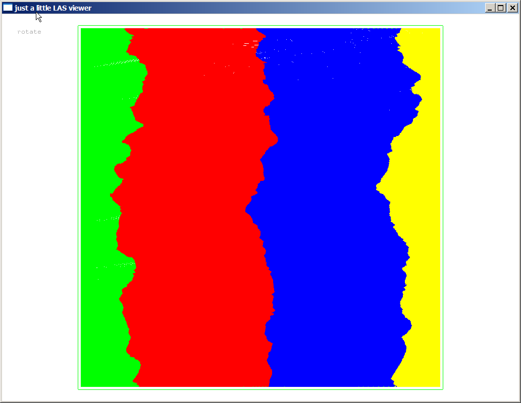
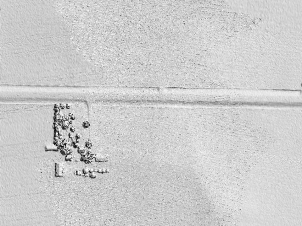
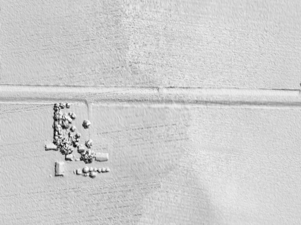
Attached you see images from a tile in Iowa with 4 flight lines that are color-coded. You also see the result that overlapping flightlines have on the resulting hillshade DEM and if you toggle back and forth between the two you get a good sense of where the overlap is and what effect is has. While the resolution may be higher it also tends to create roughness as the flightlines are rarely perfectly aligned. Here the steps I took to generate this:
(1) find out which flight lines are in the tile
lasinfo -i iowa.laz -histo point_source 1
---> result was 4 flight lines: 10010, 10011, 10012, 10013
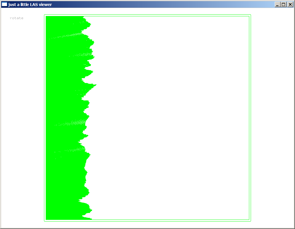
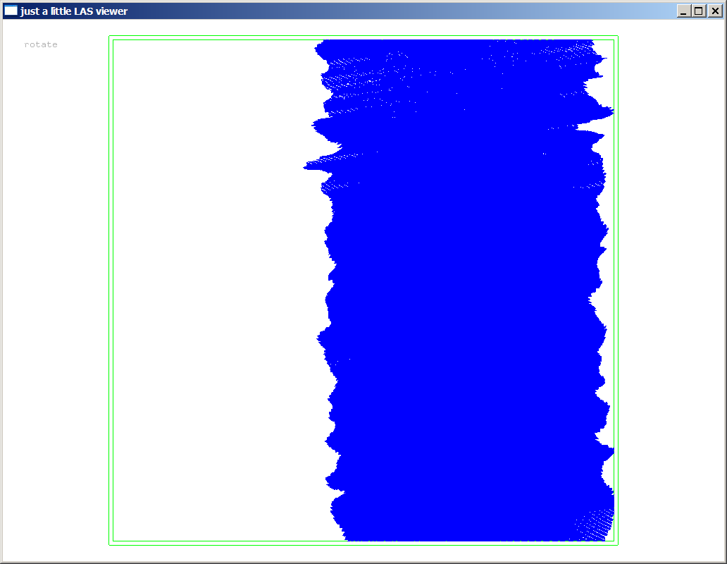
(2) show individual flight lines (press <0> <1> <2> <3> to toggle)
lasview -i iowa.laz -color_by_flight_line
(3) compute point density/spacing for individual flight line
lasinfo -i iowa.laz -compute_density -keep_point_source 10011
---> result was around 1.0 meter spacing
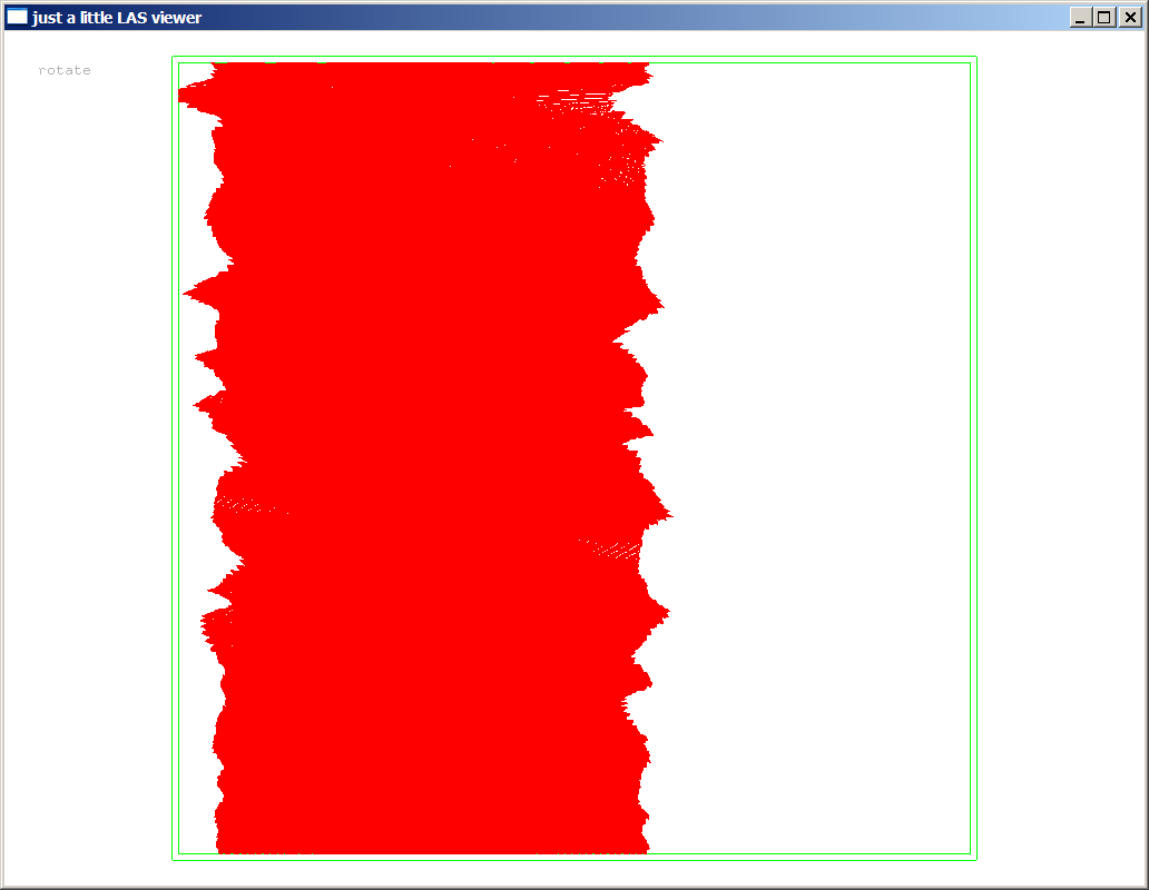
(4) classify overage points
lasoverage -i iowa.laz -step 2 -o iowa_no_over.laz
(5) show result without overlaps by dropping overage points
lasview -i iowa_no_over.laz -drop_class 12
(6) create hillshade DSM without overlaps
las2dem -i iowa_no_over.laz -drop_class 12 -hillshade -o iowa_no_over.png
Cheers,
Martin @rapidlasso
PS: Here an explaination based on what Karl Heidemann of the USGS once told me regarding "overlap" versus "overage" points: "Overlap" applies to any point in one flightline or swath that is anywhere within the boundary of another flightline. Whether or not a point is overlap is determined, basically, at the time of flight. It is a fundamentally immutable characteristic. "Overage" applies to any point not in the "tenderloin" of the flightline or swath, that is, the central core of the flightline that - when combined with the others - creates a non-overlapped and gap-less coverage of the surface. Whether or not a point is overage is determined by the operator (or software) that defines the single-coverage tenderloins of the flightlines. Hence, it is a subjective characteristic -- it depends solely on where somebody (here: lasoverage.exe) chooses to draw the boundary. The LAS specifications use the word "overlap" where they should be using the word "overage".

Veldman, Edgar
Hi Martin,
I noticed the jagged overlap edge between swaths in your screenshots and assumed that was because your data was maybe captured from an unstable platform, possibly a small helicopter or a remotely controlled unmanned aircraft…
But when I finally got around testing this on some of our data (captured from a fixed wing airplane, Leica sensor), I noticed the same jaggedness in the overlap definition. This is not what I was used to with our data, and also not what are clients are used to.
Would there be a setting I can use to avoid this from happening? I would rather have a neat edge between swaths if possible.
Or do you have some more information on how this edge is defined, so that I can maybe tweak the input data to make it work?
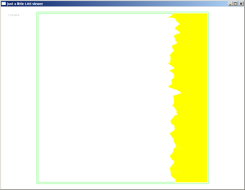
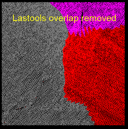
Some screenshots to clarify:
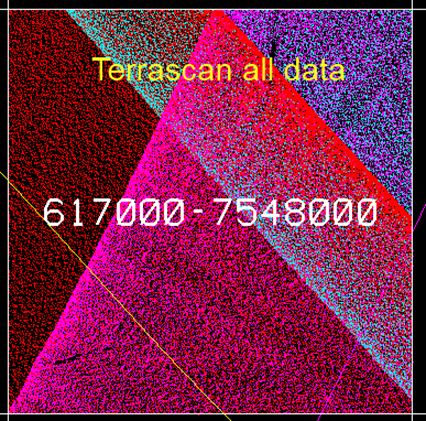
Input data
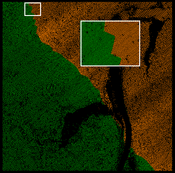
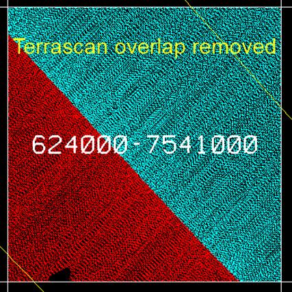
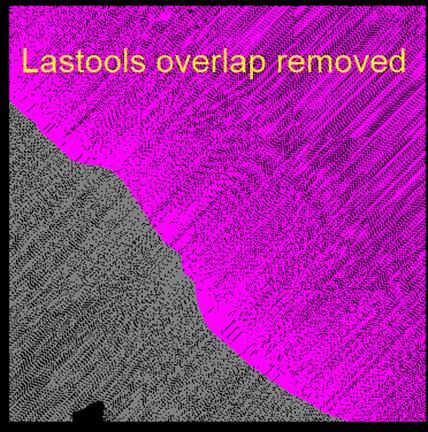
Overlap removed by Lastools
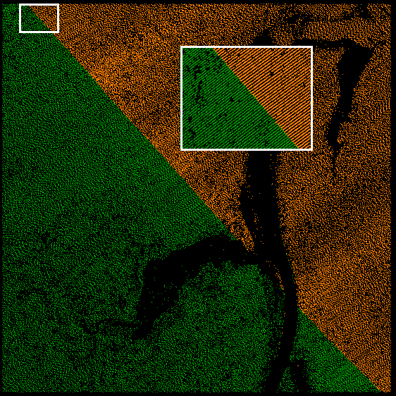
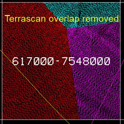
Overlap removed by another tool
Thanks,
Edgar
--
Download LAStools at
http://lastools.org/
Visit the LAStools group at
http://groups.google.com/group/lastools/
Be social with LAStools at
http://www.facebook.com/LAStools
http://www.twitter.com/LAStools
Martin Isenburg
But when I finally got around testing this on some of our data (captured from a fixed wing airplane, Leica sensor), I noticed the same jaggedness in the overlap definition. This is not what I was used to with our data, and also not what are clients are used to.
Is there anything inherently "better" about this dividing line being "straight" other than it being what another software produces? Some people actually prefer the "natural" look of my dividing line as it is - in case of a slight flight-line misalignment - much less prominent than a straight when you render a hill-shade of the terrain.
Would there be a setting I can use to avoid this from happening? I would rather have a neat edge between swaths if possible. Or do you have some more information on how this edge is defined, so that I can maybe tweak the input data to make it work?
You cannot expect get a straight line here without me writing a new tool. (-:
Regards,
Martin @rapidlasso
Martin Isenburg
I just received a message from Lewis Graham that did not make it
through to the list. He wrote:
Another consideration:
A typical reason for marking points in overlap regions as Withheld and/
or Overlap (in LAS 1.4) is due to the fact that the horizontal and
vertical accuracy of the LIDAR data is a function of the scan angle
from nadir (at least in airborne sensors using beam scanning),
decreasing as one moves away from nadir. Cutting as Martin cuts
ensures more uniform edge accuracy of the data. A straight-line cut
results in variable accuracy. Of course, one may not care about this
phenomenon and be looking only for a pretty picture….
_______________________________
Lewis Graham
Martin Isenburg
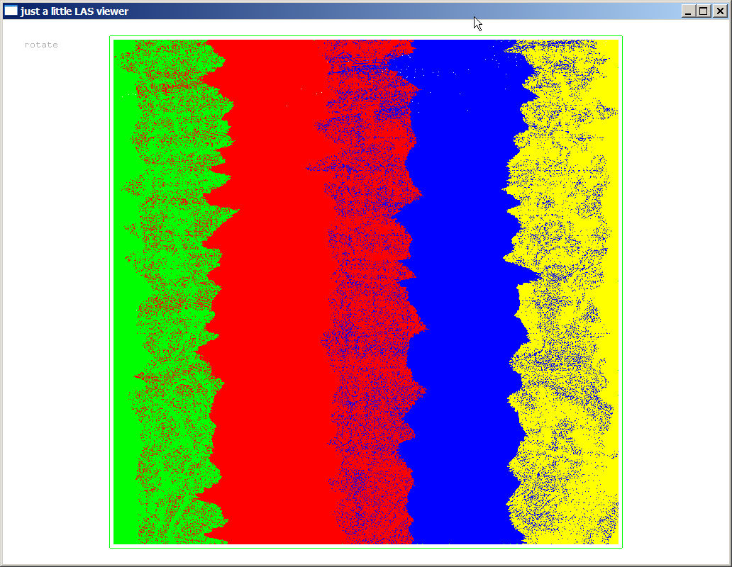
the discussion in lasoverage was a fairly important one and I have resolved it in an off-line follow up discussion. Edgar send me the LAS tiles in question and these attached as well as a few other screen shots. Edgar wrote: "With regards to your comments, and Lewis’ reply, we are not just after a nice picture. It would make sense if the jaggedness would be related to scan angle or terrain elevation, but I can’t see a relationship there. It looks like the edge is drawn at very random locations. There is probably a logic algorithm working behind the scenes but I can’t recognize it. Also, if the jaggedness would not be so spiky in places, it would maybe not be noticeable, but the noisiness and zigzag pattern I see with the overlap definition has raised some eyebrows."
And indeed, it had me baffled how the "other" software was doing such wonderfully straight cuts. How did they do it. Well ... turns out the "other" software was using the flight trajectory information to make those cute (you can actually see these auxiliary lines in the images) whereas LAStools was making its decision purely based on the scan angles stored per point. So in the end (see next email) we agreed that LAStools was - in fact - picking the points with the lowest absolute scan angle. Whether this is necessarily the best choice if the aircraft experiences heavy roll is a whole different question ... after all, the nadir scan angle only corresponds to the scan angle with the value zero when the aircraft is level.
Regards,
Martin @rapidlasso
Martin Isenburg
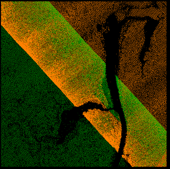
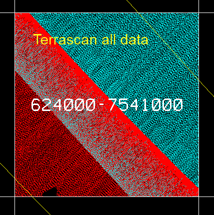
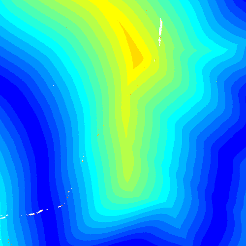
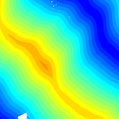
I created these two visualizations with lasgrid to prove that lasoverage was doing "the best it could" given that it has no access to the original flight trajectories and that it indeed follows the "lowest absolute scan angle" it finds in the data.
lasgrid -i 617000-7548000.laz -scan_angle_abs -lowest -false -opng -odix _scan_abs -step 2
When one looks at the way the shading flows one quickly realizes that the colors not only look pretty, but also explain why lasoverage was choosing the points the way it did in the images from the last message where Edgar was comparing lasoverage with the "other" software.
Regards,
Martin @rapidlasso

Tobias K Kohoutek
Hi Martin,
Martin Isenburg
--
Download LAStools at
http://lastools.org
Be social with LAStools at
Tobias K Kohoutek
