Re: [The LAS room] fixing wrong "scan angle rank" in LAS files
668 views
Skip to first unread message

Martin Isenburg
Aug 19, 2017, 6:43:04 AM8/19/17
to The LAS room - a friendly place to discuss specifications of the LAS format, LAStools - efficient command line tools for LIDAR processing
Hello Jose,
Thank you for sending a lasinfo report. That usually helps. However, note that for the intensity it tends to be more useful to use a bigger bin size such as '-histo intensity 64' or so. It appears the file was generated by a software called "Milan Merge_las_gkw V101216". Do you have this software? Do you know who created the file? I see the UTM zone is 23south. Just curious ... where and for what reason was this data flown?
The overall distribution as well as the scan angle average of 89.7 suggest that 90 degrees correspond to 0 zero degrees so that that the real scan angles (in scan system coordinates and not corrected for aircraft roll) can be obtained simply by subtracting 90 from the current values. You can do this with the free and open swiss army knife of LAS file processing, las2las, as follows:
las2las -i strips/*.laz ^
-translate_scan_angle -90 ^
-odir fixed -olaz ^
-cores 4
Your files are currently using GPS week time as their time stamps. I always recommend using Adjusted Standard GPS time as discussed in detail here:
Should you know the GPS week that your LiDAR was collected and assuming it was GPS week 1957 then simply add this to the command line:
las2las -i strips/*.laz ^
-translate_scan_angle -90 ^
-week_to_adjusted 1957 ^
-odir fixed -olaz ^
-cores 4
Regards,
Martin @rapidlasso
On Aug 19, 2017 3:36 AM, "Hildermes José Medeiros FIlho" <hild...@gmail.com> wrote:
to illustrate it here a report of one file:reporting all LAS header entries:file signature: 'LASF'file source ID: 43global_encoding: 0project ID GUID data 1-4: 00000000-0000-0000-0000-000000000000version major.minor: 1.2system identifier: 'Q560-'generating software: 'Milan Merge_las_gkw V101216'file creation day/year: 138/2017header size: 227offset to point data: 447number var. length records: 2point data format: 1point data record length: 28number of point records: 8678422number of points by return: 7791298 789112 88737 8599 676scale factor x y z: 0.001 0.001 0.001offset x y z: 675791.17799999996 7462655.7220000001 0min x y z: 675791.178 7462655.722 -752.603max x y z: 681781.978 7466013.133 679.280variable length header record 1 of 2:reserved 43707user ID 'LASF_Projection'record ID 34735length after header 88description 'Georeferencing Information'GeoKeyDirectoryTag version 1.1.0 number of keys 10key 1024 tiff_tag_location 0 count 1 value_offset 1 - GTModelTypeGeoKey: ModelTypeProjectedkey 2048 tiff_tag_location 0 count 1 value_offset 4326 - GeographicTypeGeoKey: GCS_WGS_84key 2054 tiff_tag_location 0 count 1 value_offset 9102 - GeogAngularUnitsGeoKey: Angular_Degreekey 2056 tiff_tag_location 0 count 1 value_offset 7030 - GeogEllipsoidGeoKey: Ellipse_WGS_84key 2057 tiff_tag_location 34736 count 1 value_offset 0 - GeogSemiMajorAxisGeoKey: 6378137key 2058 tiff_tag_location 34736 count 1 value_offset 1 - GeogSemiMinorAxisGeoKey: 6356752.314key 2059 tiff_tag_location 34736 count 1 value_offset 2 - GeogInvFlatteningGeoKey: 298.2572236key 3072 tiff_tag_location 0 count 1 value_offset 32723 - ProjectedCSTypeGeoKey: WGS 84 / UTM 23Skey 3076 tiff_tag_location 0 count 1 value_offset 9001 - ProjLinearUnitsGeoKey: Linear_Meterkey 4099 tiff_tag_location 0 count 1 value_offset 9001 - VerticalUnitsGeoKey: Linear_Metervariable length header record 2 of 2:reserved 43707user ID 'LASF_Projection'record ID 34736length after header 24description 'Double Param Array'GeoDoubleParamsTag (number of doubles 3)6.37814e+006 6.35675e+006 298.257reporting minimum and maximum for all LAS point record entries ...... processed 1000000 points ...... processed 2000000 points ...... processed 3000000 points ...... processed 4000000 points ...... processed 5000000 points ...... processed 6000000 points ...... processed 7000000 points ...... processed 8000000 points ...X 0 5990800Y 0 3357411Z -752603 679280intensity 6 15130return_number 1 7number_of_returns 1 7edge_of_flight_line 0 1scan_direction_flag 0 0classification 1 1scan_angle_rank 60 120user_data 0 0point_source_ID 43 43gps_time 498077.394337 498259.679367number of first returns: 7791298number of intermediate returns: 98012number of last returns: 7791298number of single returns: 7002186covered area in square meters/kilometers: 4470280/4.47point density: all returns 1.94 last only 1.74 (per square meter)spacing: all returns 0.72 last only 0.76 (in meters)WARNING: for return 5 real number of points by return (632) is different from header entry (676).WARNING: there are 41 points with return number 6WARNING: there are 3 points with return number 7overview over number of returns of given pulse: 7002186 1400750 240414 31868 2960 222 22histogram of classification of points:8678422 unclassified (1)
[...]
scan angle histogram with bin size 1bin 60 has 52232bin 61 has 143380bin 62 has 161768bin 63 has 147592bin 64 has 148570bin 65 has 148823bin 66 has 147594bin 67 has 147718bin 68 has 148834bin 69 has 149323bin 70 has 158333bin 71 has 150652bin 72 has 146930bin 73 has 144800bin 74 has 145827bin 75 has 144114bin 76 has 143741bin 77 has 144571bin 78 has 144332bin 79 has 157433bin 80 has 144921bin 81 has 144391bin 82 has 143360bin 83 has 142726bin 84 has 141937bin 85 has 142202bin 86 has 143177bin 87 has 153145bin 88 has 148182bin 89 has 145418bin 90 has 145475bin 91 has 144765bin 92 has 143902bin 93 has 143669bin 94 has 144267bin 95 has 143935bin 96 has 156359bin 97 has 142423bin 98 has 142065bin 99 has 142727bin 100 has 141991bin 101 has 142097bin 102 has 142333bin 103 has 141646bin 104 has 151451bin 105 has 145907bin 106 has 143151bin 107 has 143022bin 108 has 142918bin 109 has 142063bin 110 has 142237bin 111 has 141660bin 112 has 141300bin 113 has 154034bin 114 has 140831bin 115 has 140323bin 116 has 139738bin 117 has 138069bin 118 has 136071bin 119 has 131631bin 120 has 60336average scan angle 89.7026 for 8678422 element(s)

Hildermes José Medeiros FIlho
Aug 19, 2017, 4:36:17 PM8/19/17
to The LAS room - a friendly place to discuss the LAS and LAZ formats, last...@googlegroups.com
Hello, Martin!
Thanks for your answer. It will help me a lot.
I thought the "scan angle rank" should always be in the range specified by the sensor's manual.
It is awkward to see the sensor specs description as found in the file above or below the specs.
Do you know if this is common? Do I have to worry about everything? Why store scan angle rank +90 degree I do not think this was done intentionally.
But answering your questions:
I do not know this software Milan Merge_las_gkw V101216 nor have contacts with person that did the work.
This files were bought by a public organ in Rio de Janeiro.
It was a flight to surveying some part of the Tijuca forest, shantytown and others stuffs.
The projects covers 750km ^ 2
8-10 points / m ^ 2
Altimetric accuracy of 15 cm
Planimetric accuracy of 50 cm
I got curious about this data, because I saw those angles and it did not match the specs.
There are some points without "gps weekend" and some with intensity above threshold too. But this looked like data error.
These things have puzzled me, so I'm checking.
I have some control points, maybe it's good to check this "accuracy".
Best regards,
Hildermes
ps:
Best regards,
Hildermes
ps:
I'm Brazilian and the text may sound poorly written!
My brother is Canadian, but I have not written in English for years.

Ellon Mendes
Aug 21, 2017, 5:53:01 AM8/21/17
to last...@googlegroups.com
Olá Hildernes,
The scan angle rank in LAS files represent the scan angle from nadir,
where 0 means nadir direction (see [1]). So depending on the orientation
of the aircraft you may end up with angles that are beyond the sensor
max values.
Probably it's your software that is doing something weird with the
angles. Maybe a wrong configuration?
Beware that since you're using format 1 and the mean value of your scan
angles is close to the limits of the space reserved for the scan angle
(1 char) you may end up with truncated values. For example, if the real
angle of the pulse plus this strange 90 degrees shift makes the angle go
beyond the value of 128.
Best,
Ellon
[1] http://www.asprs.org/wp-content/uploads/2010/12/LAS_1_4_r13.pdf
> --
> Download LAStools at
> http://lastools.org
> http://rapidlasso.com
> Be social with LAStools at
> http://facebook.com/LAStools
> http://twitter.com/LAStools
> http://linkedin.com/groups/LAStools-4408378
> Manage your settings at
> http://groups.google.com/group/lastools/subscribe
The scan angle rank in LAS files represent the scan angle from nadir,
where 0 means nadir direction (see [1]). So depending on the orientation
of the aircraft you may end up with angles that are beyond the sensor
max values.
Probably it's your software that is doing something weird with the
angles. Maybe a wrong configuration?
Beware that since you're using format 1 and the mean value of your scan
angles is close to the limits of the space reserved for the scan angle
(1 char) you may end up with truncated values. For example, if the real
angle of the pulse plus this strange 90 degrees shift makes the angle go
beyond the value of 128.
Best,
Ellon
[1] http://www.asprs.org/wp-content/uploads/2010/12/LAS_1_4_r13.pdf
> Download LAStools at
> http://lastools.org
> http://rapidlasso.com
> Be social with LAStools at
> http://facebook.com/LAStools
> http://twitter.com/LAStools
> http://linkedin.com/groups/LAStools-4408378
> Manage your settings at
> http://groups.google.com/group/lastools/subscribe
Martin Isenburg
Aug 21, 2017, 7:51:23 AM8/21/17
to LAStools - efficient command line tools for LIDAR processing
Hello,
The scan angle rank in LAS files represent the scan angle from nadir, where 0 means nadir direction (see [1]). So depending on the orientation of the aircraft you may end up with angles that are beyond the sensor max values.
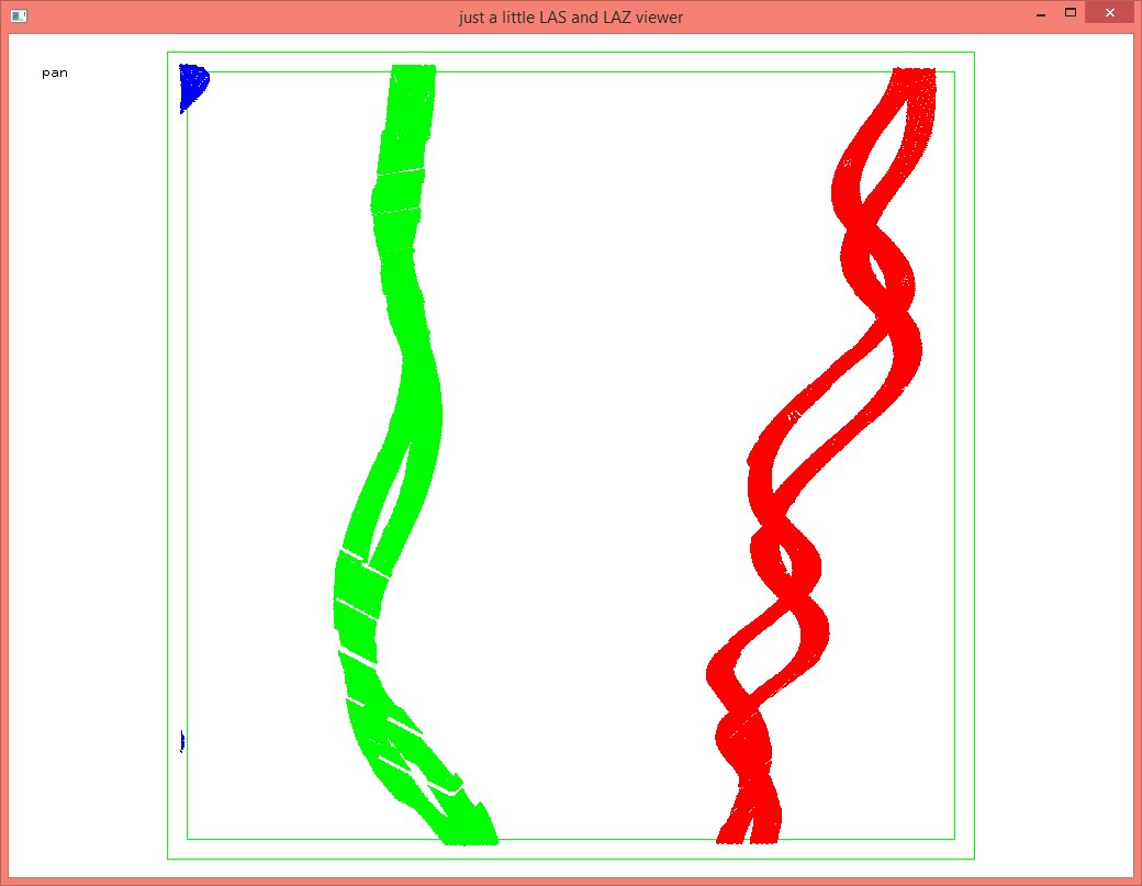
That is what the specification states but that is not necessarily what is done in practice. The easiest way to test this is simply to only keep the scan angle rank corresponding to zero and then having a look with lasview like this.
E:\LAStools\bin>lasview -i pentagon.laz -keep_scan_angle 0 0
We're using the "classified LiDAR" from the Pentagon here. Now there is potentially a whole new outrage here because not only was LiDAR leaked over the Pentagon but
(a) the pilot must have been completely drunk at the time, or
(b) the pilot had to avoid intercepting aircraft and incoming missiles.
But those are just a theory if you really insist on those being nadir scan angles. The other theory is that those are scanner system scan angles and that roll / pitch / jaw of the aircraft due to turbulence becomes visible.
(-:
Note further that a dual beam system was used. This is also evident from the lasinfo report that shows that the scanner channel field is populated (see end of message). Does anyone know which scanner hardware did that survey? Leica or Optech? I don't think that it was a RIEGL as the "crossfire" does not have a scan pattern that gives more pulses closer to the edge of the flight line (due to the oscillating mirror slowing and accelerating). That this scan uses a zigzag scanner that gets more density at the flightline edges is easy to visualize with lasgrid.
E:\LAStools\bin>lasgrid -i pentagon_LAS14.laz ^
-keep_last ^
-point_density ^
-false -set_min_max 20 40 ^
-opng
Note that I chose to map last return densities between 20 and 40 to a false color because the lasinfo report tells me that the average is around 30. Can you tell from how the two beams are arranged? I've seen Optech Pegasus data before and don't remember the beams diverging like that. Is it a Leica?
Regards,
Martin @rapidlasso
E:\LAStools\bin>lasinfo -i pentagon_LAS14.laz -cd
lasinfo (170818) report for pentagon_LAS14.laz
reporting all LAS header entries:
file signature: 'LASF'
file source ID: 0
global_encoding: 17
project ID GUID data 1-4: 8924393A-6897-443F-72A4-CFDFCCEC7C23
version major.minor: 1.4
system identifier: 'LAStools (c) by rapidlasso GmbH'
generating software: 'las2las (version 170203)'
file creation day/year: 209/2015
header size: 375
offset to point data: 924
number var. length records: 1
point data format: 6
point data record length: 30
number of point records: 0
number of points by return: 0 0 0 0 0
scale factor x y z: 0.01 0.01 0.01
offset x y z: 300000 100000 0
min x y z: 395000.00 133435.00 -4.05
max x y z: 395499.99 133934.99 46.32
start of waveform data packet record: 0
start of first extended variable length record: 0
number of extended_variable length records: 0
extended number of point records: 8044789
extended number of points by return: 7893346 125669 23476 2248 46 4 0 0 0 0 0 0 0 0 0
variable length header record 1 of 1:
reserved 43707
user ID 'LASF_Projection'
record ID 2112
length after header 495
description 'OGC WKT Coordinate System'
WKT OGC COORDINATE SYSTEM:
PROJCS["NAD_1983_StatePlane_Maryland_FIPS_1900",GEOGCS["GCS_North_American_1983",DATUM["D_North_American_1983",SPHEROID["GRS_1980",6378137,298.257222101004]
],PRIMEM["Greenwich",0],UNIT["Degree",0.0174532925199433]], PROJECTION["Lambert_Conformal_Conic"],PARAMETER["False_Easting",400000],PARAMETER["False_Northing",0
],PARAMETER["Central_Meridian",-77],PARAMETER["Standard_Parallel_1",38.3],PARAMETER["Standard_Parallel_2",39.45],PARAMETER["Latitude_Of_Origin",37.6666666666667
],UNIT["Meter",1]]
LASzip compression (version 3.0r1 c3 50000): POINT14 3
reporting minimum and maximum for all LAS point record entries ...
X 9500000 9549999
Y 3343500 3393499
Z -405 4632
intensity 0 255
return_number 1 6
number_of_returns 1 6
edge_of_flight_line 0 1
scan_direction_flag 0 1
classification 1 17
scan_angle_rank -19 19
user_data 0 0
point_source_ID 501 1108
gps_time 112971668.874616 113668156.810547
extended_return_number 1 6
extended_number_of_returns 1 6
extended_classification 1 17
extended_scan_angle -3167 3167
extended_scanner_channel 0 1
number of first returns: 7893346
number of intermediate returns: 25732
number of last returns: 7893137
number of single returns: 7767426
covered area in square units/kilounits: 251000/0.25
point density: all returns 32.05 last only 31.45 (per square units)
spacing: all returns 0.18 last only 0.18 (in units)
overview over extended number of returns of given pulse: 7767426 204634 63701 8800 204 24 0 0 0 0 0 0 0 0 0
overview over extended number of returns of given pulse: 7767426 204634 63701 8800 204 24 0 0 0 0 0 0 0 0 0
histogram of classification of points:
5650833 unclassified (1)
2358860 ground (2)
1430 noise (7)
33666 bridge deck (17)
+-> flagged as withheld: 1430
+-> flagged as extended overlap: 2931813
Ellon Paiva
Nov 8, 2017, 9:44:15 AM11/8/17
to LAStools - efficient tools for LiDAR processing
Hello again,
Late thanks for your answer, Martin. It made me realize that my angle data was also in scanner system scan angles! Now I'm re-opening this topic because it's my turn to have some questions about correcting scan angles. :)
I have a dataset in LAS v1.4, point format 6, where scan angles represent scanner system scan angles (zero matches down, 90deg matches right wing). I have a file with the timestamped drone trajectory, I would like to transform it in such way that zero means nadir, and confirming the specifications, if possible. But I'm having some problems understanding the specification for scan angles.
From the LAS v1.4 specification file [1], the scan_angle_rank value should compensate for roll, but it does not mention the pitch angle. But for the scan angle from the format 6 and on, the spec says "The Scan Angle is a signed short that represents the rotational position of the emitted laser pulse with respect to the vertical of the coordinate system of the data". So , if my data is georeferenced in a north-east-up frame, would it be the angle between two vectors, the laser pulse vector and the down vector, in this reference frame? In this case it means that I have to compensate for the 3D rotation of the airplane. Am I right?
To add more to my confusion, further ahead in the same paragraph of the Scan Angle, it says: "Counter-Clockwise rotation, as viewed from the rear of the sensor, facing in the along-track (positive trajectory) direction, is positive". From this I understood that:
And to finish, another somewhat related question: Is the scan_angle_rank limits in lasinfo output for LAS file with point format 6 computed "on-the-fly" from the extended_scan_angle?
Regards,
Ellon
[1] https://www.asprs.org/a/society/committees/standards/LAS_1_4_r13.pdf
Late thanks for your answer, Martin. It made me realize that my angle data was also in scanner system scan angles! Now I'm re-opening this topic because it's my turn to have some questions about correcting scan angles. :)
I have a dataset in LAS v1.4, point format 6, where scan angles represent scanner system scan angles (zero matches down, 90deg matches right wing). I have a file with the timestamped drone trajectory, I would like to transform it in such way that zero means nadir, and confirming the specifications, if possible. But I'm having some problems understanding the specification for scan angles.
From the LAS v1.4 specification file [1], the scan_angle_rank value should compensate for roll, but it does not mention the pitch angle. But for the scan angle from the format 6 and on, the spec says "The Scan Angle is a signed short that represents the rotational position of the emitted laser pulse with respect to the vertical of the coordinate system of the data". So , if my data is georeferenced in a north-east-up frame, would it be the angle between two vectors, the laser pulse vector and the down vector, in this reference frame? In this case it means that I have to compensate for the 3D rotation of the airplane. Am I right?
To add more to my confusion, further ahead in the same paragraph of the Scan Angle, it says: "Counter-Clockwise rotation, as viewed from the rear of the sensor, facing in the along-track (positive trajectory) direction, is positive". From this I understood that:
- I should consider a 2D plane formed by the down vector and the plane direction vector, both in the georeferenced frame, and then consider the angle with every beam vector laying on one side to be be negative (the left side if looking from behind the airplane), and to be positive if on the other side of this 2D plane (the right side).
- If the airplane has some pitch angle we would have discontinuous scan angles, since the scan angle when crossing this 2D plane would not be zero.
Did I got it right?
And to finish, another somewhat related question: Is the scan_angle_rank limits in lasinfo output for LAS file with point format 6 computed "on-the-fly" from the extended_scan_angle?
Regards,
Ellon
[1] https://www.asprs.org/a/society/committees/standards/LAS_1_4_r13.pdf

Evon Silvia
Nov 8, 2017, 12:06:21 PM11/8/17
to last...@googlegroups.com
You're correct on #1 but not #2. The Scan Angle Rank should be roll-compensated such that nadir is always zero. In addition, only the cross-track component of the scanner angle is to be included – any forward, backward, or pitch angles should be removed in order to be compliant. In other words, if you have a 2D plane stretching vertically from nadir (as defined by gravity) and horizontally along the wing, the Scan Angle Rank is the angle, from nadir, measured in that plane. It takes some fancy trig to convert back and forth, but it's not so bad as long as you have the SBETs.
Internally, at QSI we discuss the differences as the following:
- True nadir angle - angular offset from true nadir (as defined by gravity) to the pulse vector
- Cross-track nadir angle - component of the true nadir angle in a 2D plane along the aircraft wing - this is the Scan Angle Rank
- Along-track nadir angle - component of the true nadir angle in a 2D plane along the aircraft nose - this is explicitly excluded from the Scan Angle Rank
- Scanner angle - angular offset from the scanner's nadir, regardless of its actual orientation in real space - unclear whether this would be true, cross-track, or along-track
- Palmer angle - I'm a little unclear on this, but I believe it to be the same as along-track nadir angle.
There is currently no formal way to include the along-track component of the nadir angle, but of course that could be done using extrabytes in LAS 1.4. This has been registered with the LWG as a desired addition to the LAS spec.
Since this is a common question (and one I asked a couple years ago), I believe it to be worthwhile for the LWG to publish some clarification on the issue.
Evon
--
Evon Silvia PLS
QSI Solutions Developer
ASPRS LAS Working Group Chair
517 SW 2nd Street, Suite 400, Corvallis, OR 97333
Martin Isenburg
Nov 8, 2017, 2:57:40 PM11/8/17
to LAStools - efficient command line tools for LIDAR processing
Hello,
I believe that there is an enormous amount of LiDAR out there where the scan angle rank (and not also the scan angle) is in local scanner coordinates, which is also nice to have as this information allows to easily clip those parts of the LiDAR shot by the moments of the mirror movement when it was about to turn around (the less precise and unnecessarily dense parts of an oscillating mirror systems). Maybe we could use a bit of the global encoding bit mask to specify whether local or roll-compensated angles are stored. That would make it easy to fix those Exabytes of existing LAS / LAZ files that have it one way or the other (just flip the bit to the right state).
Regards,
Martin
Ellon Mendes
Nov 9, 2017, 6:16:43 PM11/9/17
to last...@googlegroups.com
Hello,
@Evon: Thanks for your answer. Now it's clear to me that I'm not the only one with doubts on how to interpret the specification about the scan angle. The terms you used are interesting. I think that my interpretation was what you call "True nadir angle", but it's nice to have a list of other possible ones. I think that for now I should just find one definition that fits my needs and convert the scan angles of my cloud to match this definition. Btw, what is "SBET"?
@Martin: Indeed, using some bits to encode the meaning of the scan angle would be useful, and not only if it was roll-compensated, given the possible interpretations of extended_scan_angles.
Best,
Ellon
On 11/08/2017 08:56 PM, Martin Isenburg
wrote:
Hello,
I believe that there is an enormous amount of LiDAR out there where the scan angle rank (and not also the scan angle) is in local scanner coordinates, which is also nice to have as this information allows to easily clip those parts of the LiDAR shot by the moments of the mirror movement when it was about to turn around (the less precise and unnecessarily dense parts of an oscillating mirror systems). Maybe we could use a bit of the global encoding bit mask to specify whether local or roll-compensated angles are stored. That would make it easy to fix those Exabytes of existing LAS / LAZ files that have it one way or the other (just flip the bit to the right state).
Regards,
Martin
On Wed, Nov 8, 2017 at 5:55 PM, Evon Silvia <esi...@quantumspatial.com> wrote:
You're correct on #1 but not #2. The Scan Angle Rank should be roll-compensated such that nadir is always zero. In addition, only the cross-track component of the scanner angle is to be included – any forward, backward, or pitch angles should be removed in order to be compliant. In other words, if you have a 2D plane stretching vertically from nadir (as defined by gravity) and horizontally along the wing, the Scan Angle Rank is the angle, from nadir, measured in that plane. It takes some fancy trig to convert back and forth, but it's not so bad as long as you have the SBETs.
Internally, at QSI we discuss the differences as the following:
- True nadir angle - angular offset from true nadir (as defined by gravity) to the pulse vector
- Cross-track nadir angle - component of the true nadir angle in a 2D plane along the aircraft wing - this is the Scan Angle Rank
- Along-track nadir angle - component of the true nadir angle in a 2D plane along the aircraft nose - this is explicitly excluded from the Scan Angle Rank
- Scanner angle - angular offset from the scanner's nadir, regardless of its actual orientation in real space - unclear whether this would be true, cross-track, or along-track
- Palmer angle - I'm a little unclear on this, but I believe it to be the same as along-track nadir angle.
There is currently no formal way to include the along-track component of the nadir angle, but of course that could be done using extrabytes in LAS 1.4. This has been registered with the LWG as a desired addition to the LAS spec.
Since this is a common question (and one I asked a couple years ago), I believe it to be worthwhile for the LWG to publish some clarification on the issue.
Evon
-- Evon Silvia PLS QSI Solutions DeveloperASPRS LAS Working Group Chair Quantum Spatial517 SW 2nd Street, Suite 400, Corvallis, OR 97333 P: (541) 452-8502 E: esi...@quantumspatial.com
Evon Silvia
Nov 9, 2017, 6:46:09 PM11/9/17
to last...@googlegroups.com
It doesn't seem unreasonable to me to use one of the Global Encoding bits for this purpose. Martin formally proposed this here: https://github.com/ASPRSorg/LAS/issues/41
SBET = Smoothed Best Estimate Trajectory. Sorry, I forget that not all the jargon is standard.
Evon
Reply all
Reply to author
Forward
0 new messages