Hal-Con 2015 Pinball Machine Project

Peter-Frank Spierenburg

Baha Baydar
--
---
You received this message because you are subscribed to the Google Groups "Halifax Makerspace" group.
To unsubscribe from this group and stop receiving emails from it, send an email to halifaxmakersp...@googlegroups.com.
To post to this group, send email to halifaxm...@googlegroups.com.
Visit this group at http://groups.google.com/group/halifaxmakerspace.
For more options, visit https://groups.google.com/d/optout.

Shawn Wilson

Sandy Walsh
Shawn Wilson
Sandy Walsh
Shawn Wilson
Peter-Frank Spierenburg
Baha Baydar
Shawn Wilson

Adam Cox

Adam Smith
On Tuesday, December 16, 2014 9:45:27 AM UTC-4, Peter-Frank Spierenburg wrote:
Sandy Walsh
Shawn Wilson
--
---
You received this message because you are subscribed to the Google Groups "Halifax Makerspace" group.
To unsubscribe from this group and stop receiving emails from it, send an email to halifaxmakersp...@googlegroups.com.
To post to this group, send email to halifaxm...@googlegroups.com.
Visit this group at http://groups.google.com/group/halifaxmakerspace.
For more options, visit https://groups.google.com/d/optout.
Peter-Frank Spierenburg
Sandy Walsh
On Sunday, December 21, 2014 11:16:25 PM UTC-4, Shawn Wilson wrote:
Sandy Walsh

Chris McDonald
Starbucks isnt open. Discovery centre?
--
Chris McDonald
I‘m here at the discovery centre and will be until 7:30. I can stick around until 9 if people show up.
Baha Baydar
Isn't the meeting on Thursday?
Chris McDonald
Oh crap, your right. Its wrong in my calandar.
Baha Baydar
Well if that Starbucks isn't open that late we should plan on meeting at the center instead anyway?
Chris McDonald
Sandy Walsh
Peter-Frank Spierenburg
Shawn Wilson
--
---
You received this message because you are subscribed to the Google Groups "Halifax Makerspace" group.
To unsubscribe from this group and stop receiving emails from it, send an email to halifaxmakersp...@googlegroups.com.
To post to this group, send email to halifaxm...@googlegroups.com.
Visit this group at http://groups.google.com/group/halifaxmakerspace.
For more options, visit https://groups.google.com/d/optout.
Shawn Wilson

Ryan Neily
Chris McDonald
Peter-Frank Spierenburg

Dylan Fish
Peter-Frank Spierenburg
Chris McDonald
Sandy Walsh
Peter-Frank Spierenburg
Chris McDonald
Peter-Frank Spierenburg
Shawn Wilson
I'm getting over pneumonia and can't make it, but I'm hoping someone will take good notes and share them. :)
--
Adam Cox
On Thursday, January 22, 2015 at 5:21:00 PM UTC-4, Shawn Wilson wrote:
I'm getting over pneumonia and can't make it, but I'm hoping someone will take good notes and share them. :)
On Jan 21, 2015 4:32 PM, "Peter-Frank Spierenburg" <spie...@gmail.com> wrote:
This is a reminder that tomorrow is our brainstorming meeting which will be at the Discovery Centre (1593 Barrington Street) from 6:30 to 8:30. I've invited some Hal-Con people as well:--Shawn Kehoe is the fearless leader of the Hal-Con Gaming Team. If it games, Shawn knows about it.Brian Crocker is a member of the Gaming Team who knows everything there is to know about games requiring an electrical socket.Travis Whalen is Hal-Con's Director of Design. If it says Hal-Con on it, Travis probably designed it.In the event that you arrive late, and the doors are locked, please phone me: 902-240-2984 and someone will let you in.Cheers!
---
You received this message because you are subscribed to the Google Groups "Halifax Makerspace" group.
To unsubscribe from this group and stop receiving emails from it, send an email to halifaxmakerspace+unsubscribe@googlegroups.com.
To post to this group, send email to halifaxmakerspace@googlegroups.com.
Peter-Frank Spierenburg

Jordan Vallis
Shawn Wilson
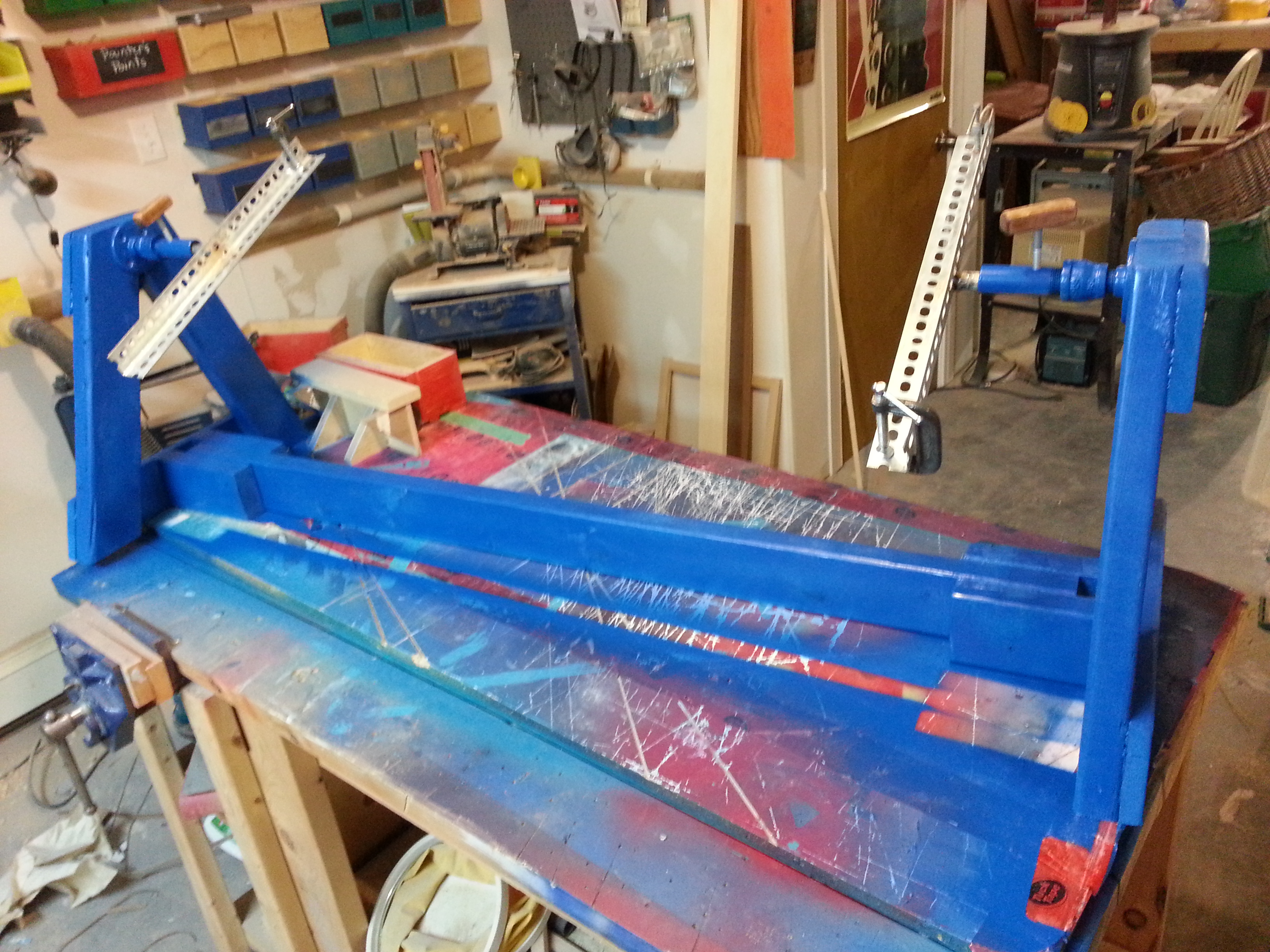
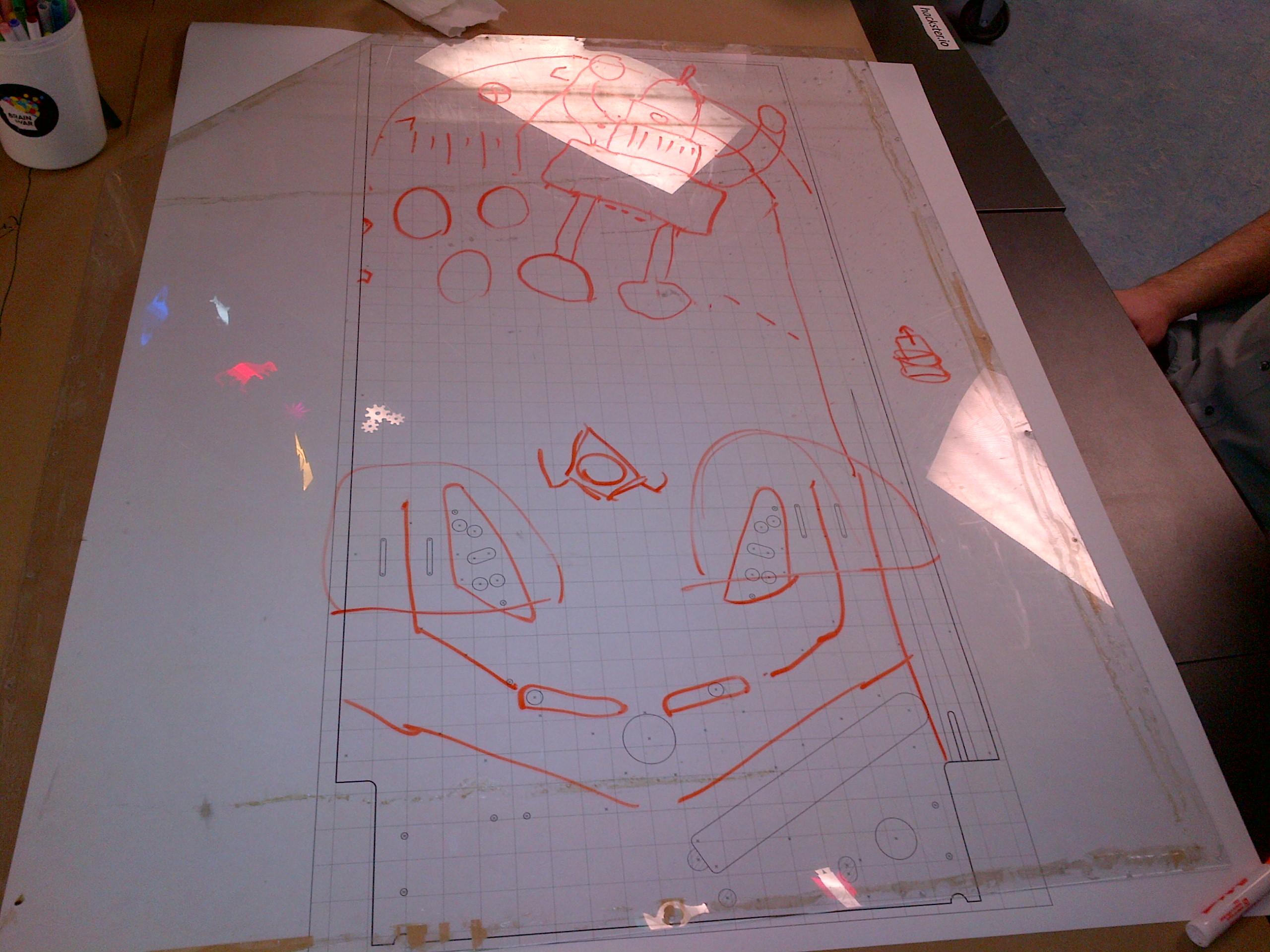
Pics!
--
---
You received this message because you are subscribed to the Google Groups "Halifax Makerspace" group.
To unsubscribe from this group and stop receiving emails from it, send an email to halifaxmakersp...@googlegroups.com.
To post to this group, send email to halifaxm...@googlegroups.com.
Jordan Vallis
Peter-Frank Spierenburg
Shawn Wilson
--
---
You received this message because you are subscribed to the Google Groups "Halifax Makerspace" group.
To unsubscribe from this group and stop receiving emails from it, send an email to halifaxmakersp...@googlegroups.com.
To post to this group, send email to halifaxm...@googlegroups.com.
Visit this group at http://groups.google.com/group/halifaxmakerspace.
For more options, visit https://groups.google.com/d/optout.
Shawn Wilson
Peter-Frank Spierenburg
Shawn Wilson
- Packages of full sheets of sandpaper: ~100, ~220 and ~320 grit
- Packages of 5" round hook and loop (NOT sticky-backed) sandpaper for oscillating sanders (these have a bunch of small holes in the paper for dust collection): ~100, ~220 and ~320 grit
- Roll of shop towels (they're blue)
- small sheet of cloroplast (corrugated plastic, like political signs are made from), if possible and cheap. Just for mixing the Bondo on. We can make do with
- spray cans of primer. If we use 80 sq feet as the approx area to cover with one coat of primer (rough estimate, and I'm assuming we want the inside and outside of the cabinet and backbox). I'm guessing that's about 8 cans, which seems excessive, but you might want to talk to someone in the paint department. Chris, do you know better way (spray gun, etc.)?
- 1 quart Bondo (NOT Bondo Hair, which has long strands and is for rougher, larger repairs)
- An extra tube of cream hardener for Bondo, if possible (It sucks to run out of Bondo before hardener)
- Disposable applicators. These are usually cheap flexible rubbery plastic and come in different widths. Also at Princess Auto and some Dollaramas. I'll have putty knives in case you can't find these cheap.
Peter-Frank Spierenburg
Chris McDonald
Chris McDonald
Adam Smith
Adam Smith
Peter-Frank Spierenburg
Peter-Frank Spierenburg
Shawn Wilson
Shawn Wilson
Peter-Frank Spierenburg
I am certain they would work.
Chris McDonald
Shawn Wilson
What diodes are you looking for? I have several kits.
Chris McDonald
Shawn Wilson
Chris McDonald
Shawn Wilson
I'm running a bit late. I should be in by 10 or 1030.
Adam Smith
https://www.youtube.com/watch?v=434uO7jxjck
https://www.youtube.com/watch?v=xfv8HxaWlz4
https://www.youtube.com/watch?v=Bobwzj0Nfno
https://www.youtube.com/watch?v=Wb6bGHxGwY8
https://www.youtube.com/watch?v=zBLcig7Mx2E
Chris McDonald
--
Chris McDonald

Colin O'Flynn
As a quick general question/derailment of the thread – would you want some VFD displays for this project? I’ve got two that look like this: http://www.newae.com/older/portfolio/stann/stann_VFD162S.jpeg
The VFD look is somewhat retro, so might fit with the pinball machine. I’ve probably got the pinout/interface somewhere, I think it’s just serial ASCII. Be aware they take a large current (like 1A@5V) and have a somewhat high voltage on them, so shouldn’t be easily touchable.
Not in a major rush so don’t need to figure it out now, but wanted to float the idea in case it worked with what you were doing.
Regards,
-Colin O’Flynn
Chris McDonald
Shawn Wilson
I have an oscilloscope with no probes. It's an old one, but last I checked, it powered up. If that could be useful, let me know.
Adam Smith
https://www.youtube.com/watch?v=4PcAHGrT3CU
Shawn Wilson
Peter-Frank Spierenburg
Peter-Frank Spierenburg
Chris McDonald
--
Adam Smith
Shawn Wilson
Cool. Not sure where we're sitting. We are just Ps though. :)
Maybe I'll see you there? I have front row seats with family and a VIP pass for myself.
Adam Smith
Shawn Wilson
I'm likely going to be late tomorrow evening, as I'm likely going to have to work late while in the valley. I will definitely show up at some point though. I have the chrome bit of the coin door detached and cleaned somewhat now, I'll bring it with me and it can be re-chromed whenever
--
---
You received this message because you are subscribed to the Google Groups "Halifax Makerspace" group.
To unsubscribe from this group and stop receiving emails from it, send an email to halifaxmakersp...@googlegroups.com.
To post to this group, send email to halifaxm...@googlegroups.com.
Visit this group at http://groups.google.com/group/halifaxmakerspace.
For more options, visit https://groups.google.com/d/optout.
Adam Smith
http://www.cotek.com.tw/upload/PDF/AK350.PDF
http://www.cotek.com.tw/upload/PDF/AK450.PDF
Chris McDonald
--
Adam Smith
Peter-Frank Spierenburg


Shawn Wilson
--
---
You received this message because you are subscribed to the Google Groups "Halifax Makerspace" group.
To unsubscribe from this group and stop receiving emails from it, send an email to halifaxmakersp...@googlegroups.com.
To post to this group, send email to halifaxm...@googlegroups.com.
Visit this group at http://groups.google.com/group/halifaxmakerspace.
For more options, visit https://groups.google.com/d/optout.
Chris McDonald
Peter-Frank Spierenburg
Can you measure the resistances on as many pinball coils you can find?
Adam Cox

Real O'Neil
I'm way late, but only thought of it like now...If you guys want arcade buttons, I have quite a few of them I'd be willing to donate if needed.
Chris McDonald
Chris McDonald
Peter-Frank Spierenburg
Shawn Wilson
Chris McDonald
Peter-Frank Spierenburg

Evan d'Entremont
...
Shawn Wilson
Adam Smith
You will need:
- Visual Pinball 9.9.1 (registration) or Visual Pinball 9.1.5 (what I'm using)
- PinMAME (registration) or rehosted
- VBS scripts (registration) or rehosted
- Space Shuttle table portrait or landscape (registration) or rehosted
- Space Shuttle ROM files (registration) or rehosted
- Install Visual Pinball and PinMAME. PinMAME will install to whatever folder its extracted to, and doesn't have a typical installer.
- Extract the VBS scripts to Visual Pinball\Tables
- Extract the table files to Visual Pinball\Tables
- Place the ROM zip in PinMAME\roms and don't extract it
- Run Visual Pinball, load the table, click play
- ?????
- profit!
Controls are:
5 - insert credit
1 - start game
Enter - plunger
L Shift, R Shift - flippers
Z, / - nudge table