Small group project: table saw blade angle gauge
27 views
Skip to first unread message

Shawn Wilson
Feb 7, 2018, 9:31:53 AM2/7/18
to halifaxm...@googlegroups.com
I would love to have a digital angle gauge to set the table saw angle. I think they sell for $40-50 each. I want to make one for the Makerspace and one for myself. I often have my phone charging when I am in the shop, and hate to unplug it to use an app.
Features:
Small
battery powered
3d printed case with magnets on one side
Two 8 segment displays (0-90)
Auto off
I'm thinking you'd put the magnet side to the saw top to calibrate it as you turn it on, or there'd be a button to press to calibrate. If anyone would like to help with any of the stages: determining specs, identifying components to use, prototyping electronics, PCB design (possibly), and 3D modelling/printing, jump in here. We can work together physically or asynchronously depending on schedules.
Without having investigated it at all, I am thinking of using an accelerometer, attiny, cr2032 besause I have them on hand.

Bill Morrow
Feb 7, 2018, 4:39:09 PM2/7/18
to Halifax Makerspace
I know nothing about accelerometers. What kind of angular resolution would you get? You might be on to something.
Here's an idea: https://www.cloudynights.com/topic/589521-37-dobsonian-dsc-for-diy-makers/ Put something like his setting circle coaxial with the shaft the arbor tilts on, like this fellow has done for rotating antennae.
I have an Inkscape extension which generates the pattern read by optical encoders, see attached svg. The bits get pretty tiny when there are 4096 of them around a 15cm disk. But the optical components are also tiny (see attached datasheet for phototransistors), so in theory this is buildable. It might have to be a photographic effort instead of laser printer, or easier, make it twice as big.
If you only need one quadrant, that makes it a little easier.
12 bits gives you 360/4096 or about one tenth of a degree resolution, which is a bit ridiculous. An attiny would support 9 bits (leaving to digital pins to drive the display?) and so 0.7 degree resolution. The optical components would be $10, a circuit board another $10. A visit to the optometrist after trying to assemble it... depends on your benefits.
Keeping dust out might be challenging, which is why your approach might be better. Plus yours is portable for other uses.
Bill Morrow
Feb 7, 2018, 4:40:21 PM2/7/18
to Halifax Makerspace
Forgot the second link to the antenna rotator: http://www.qsl.net/oe5jfl/encoder.htm

Peter-Frank Spierenburg
Feb 7, 2018, 5:01:22 PM2/7/18
to halifaxm...@googlegroups.com
I am interested. I have much experience with accelerometers. I am working on adding one to the sled of the MaslowCNC i intend to build.
However, I am not super clear on what you want to measure...
--
---
You received this message because you are subscribed to the Google Groups "Halifax Makerspace" group.
To unsubscribe from this group and stop receiving emails from it, send an email to halifaxmakerspace+unsubscribe@googlegroups.com.
To post to this group, send email to halifaxmakerspace@googlegroups.com.
Visit this group at https://groups.google.com/group/halifaxmakerspace.
For more options, visit https://groups.google.com/d/optout.
Shawn Wilson
Feb 7, 2018, 5:09:44 PM2/7/18
to halifaxm...@googlegroups.com
Oh, Bill, you and your rotary encoders. :)
Peter, I want to magnet the gauge to the raised table saw blade to get it's angle relative to the table's surface (can't assume the table surface is level), so that it will give a continuous reading as the tablesaw's blade angle is adjusted.
I would hope for .5 degree resolution, maybe? I have no idea if that's achievable.
On Wed, Feb 7, 2018 at 6:01 PM Peter-Frank Spierenburg <spie...@gmail.com> wrote:
I am interested. I have much experience with accelerometers. I am working on adding one to the sled of the MaslowCNC i intend to build.However, I am not super clear on what you want to measure...On Feb 7, 2018 10:31 AM, "Shawn Wilson" <sh...@glassgiant.com> wrote:I would love to have a digital angle gauge to set the table saw angle. I think they sell for $40-50 each. I want to make one for the Makerspace and one for myself. I often have my phone charging when I am in the shop, and hate to unplug it to use an app.Features:Smallbattery powered3d printed case with magnets on one sideTwo 8 segment displays (0-90)Auto offI'm thinking you'd put the magnet side to the saw top to calibrate it as you turn it on, or there'd be a button to press to calibrate. If anyone would like to help with any of the stages: determining specs, identifying components to use, prototyping electronics, PCB design (possibly), and 3D modelling/printing, jump in here. We can work together physically or asynchronously depending on schedules.Without having investigated it at all, I am thinking of using an accelerometer, attiny, cr2032 besause I have them on hand.--
---
You received this message because you are subscribed to the Google Groups "Halifax Makerspace" group.
To unsubscribe from this group and stop receiving emails from it, send an email to halifaxmakersp...@googlegroups.com.
To post to this group, send email to halifaxm...@googlegroups.com.
Visit this group at https://groups.google.com/group/halifaxmakerspace.
For more options, visit https://groups.google.com/d/optout.
--
---
You received this message because you are subscribed to the Google Groups "Halifax Makerspace" group.
To unsubscribe from this group and stop receiving emails from it, send an email to halifaxmakersp...@googlegroups.com.
To post to this group, send email to halifaxm...@googlegroups.com.
Bill Morrow
Feb 8, 2018, 9:19:43 AM2/8/18
to Halifax Makerspace
https://electronics.stackexchange.com/questions/33374/choosing-an-accelerometer is a discussion along the same lines. Nothing conclusive, just speculation. But it does sound like your idea will work, Shawn. The orientation you mount your accelerometer at might be important, e.g. stay in the most linear part of the sine curve of 2 axes at the blade angle you care to adjust most frequently.
The difference between the sine of 45 degrees ( 0.707..) and the sine of 44.5 degrees (0.706...) is -0.0062. You need 8 bits (1 in 256) to be able to see this difference.
The difference between the sine of 0 degrees ( 0.0) and the sine of 0.5 degrees (0.001...) is 0.009. You need only 7 bits (1 in 128) to be able to see this difference.
The one in my phone (SMB380) is apparently 10 bit resolution, and a protractor app I just installed definitely can sense a 0.5 degree change.
Rotary encoders are always the answer, Shawn. Except when sawdust is involved.
Shawn Wilson
Feb 8, 2018, 10:01:49 AM2/8/18
to halifaxm...@googlegroups.com
Cool. I will bring in an accelerometer or two, unless you have a preferred type, Peter. ATTINY85 can do 10 bit adc, unless there's a reason to go with something else?
Bill Morrow
Feb 8, 2018, 12:10:03 PM2/8/18
to Halifax Makerspace
Does your accelerometer have digital output?
E.g. https://www.sparkfun.com/products/12756 gives you 12 bit resolution via I2C.
Shawn Wilson
Feb 12, 2018, 9:10:49 AM2/12/18
to halifaxm...@googlegroups.com
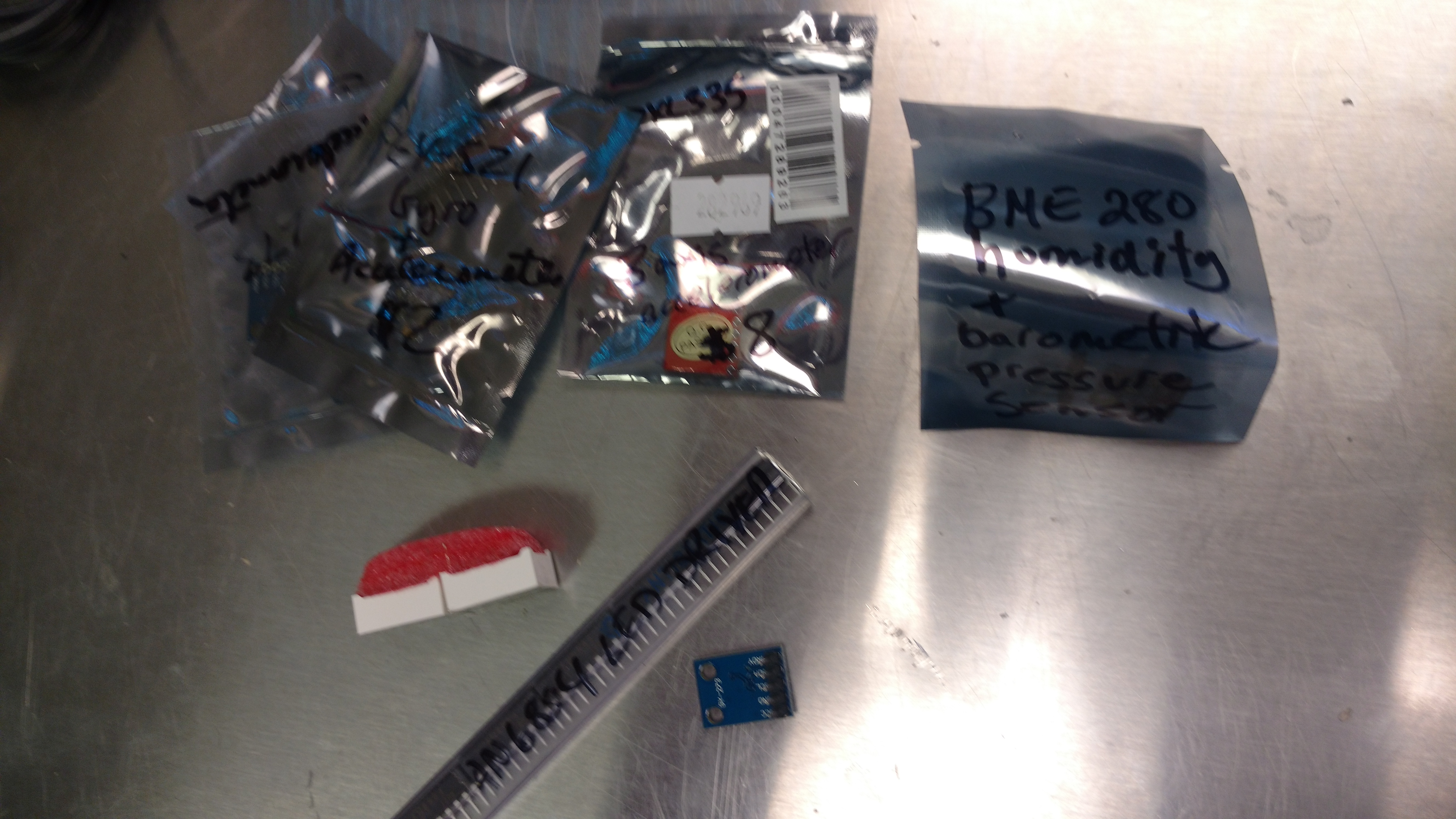
I brought in two or three types of accelerometers. Peter, per your musings (meaning I won't hold it against you if it doesn't work), one has a gyro. Also brought in a couple 8 segment displays and led drivers. They're in a plastic bin on the white shelf. If anyone, has a chance to get them breadboarded before me, have at it. Or if you have a preferred accelerometer we aren't locked into any of the parts I brought in to test.
Shawn
Shawn Wilson
Feb 23, 2018, 8:05:50 PM2/23/18
to halifaxm...@googlegroups.com
I will be heading in tomorrow night for Project Night, probably around 6 or 6:30, with the intent to breadboard some of this. Anyone who wants to help is welcome. I am not sure if the stuff I brought in will work, so if it doesn't, I'll find something else to work on. :)
Some reminders:
Saturday's are project night
This Sunday is IoT 101 at the Central Library, 2-4pm.
Open House is Sunday 1-5pm.
Bill Morrow
Feb 23, 2018, 9:33:30 PM2/23/18
to Halifax Makerspace
On Friday, 23 February 2018 21:05:50 UTC-4, Shawn Wilson wrote:
Anyone who wants to help is welcome.
My wife is away, so I should be there Saturday night.
The accelerometer gives you the acceleration due to gravity (and other acceleration if it's moving) in three axes (x, y, z), right?
This is one of them: GY-273?
If your gauge is flat on the saw table and pushed square against the saw blade when you push the calibrate button, read the three accelerations and call them (calibX, calibY, calibZ).
Then put the saw blade at your desired angle. With the gauge flat against the blade push the measure button and read (measX, measY, measZ).
According to math, the cosine of the angle between these two vectors is their dot product divided by the product of their magnitudes, and the sine is the magnitude of their cross product divided by the product of their magnitudes. The tangent is the magnitude of cross product divided by the dot product.
#include <math.h>
#ifndef M_PI
#ifndef M_PI
#define M_PI 3.14159265358979323846
#endif
double radians2Degrees = 180.0 * M_PI;
...
...
calibMagnitude = sqrt(calibX*calibX + calibY*calibY + calibZ*calibZ);
measMagnitude = sqrt(measX*measX + measY*measY + measZ*measZ);
magnitudeProduct = calibMagnitude*measMagnitude;
dotProduct = calibX*measX + calibY*measY + calibZ*measZ;
thetaDot = acos(dotProduct / magnitudeProduct); // in radians
Serial.print("dot product approach thinks angle is "); Serial.println(thetaDot * radians2Degrees);
// cross product is harder

crossX = calibY*measZ - calibZ*measY;
crossY = calibZ*measX - calibX*measZ;
crossZ = calibZ*measY - calibY*measX;
crossMagnitude = sqrt(crossX*crossX + crossY*crossY + crossZ*crossZ);
thetaCross = asin(crossMagnitude / magnitudeProduct); // in radians
Serial.print("cross product approach thinks angle is "); Serial.println(thetaCross * radians2Degrees);
thetaAtan = atan2(crossMagnitude, dotProduct);
Serial.print("atan2 approach thinks angle is "); Serial.println(thetaAtan * radians2Degrees);
Depending on how wide the angle you measure is, either the sine approach or the cosine approach will be more accurate. Since the angle between the blade and the table is between 45 degrees and 90, I think you want to use the cross product approach.
This guy has a good story: http://johnblackburne.blogspot.ca/2012/05/angle-between-two-3d-vectors.html and a respondent to his post has another approach. They both like the atan2() approach.
P.S. Hard to believe I actually knew this stuff once.
Shawn Wilson
Feb 23, 2018, 9:39:04 PM2/23/18
to halifaxm...@googlegroups.com
Cool. I think that's one of the ones I brought in.

Shawn Wilson
Feb 24, 2018, 10:52:15 PM2/24/18
to Halifax Makerspace
So after much playing around tonight, Bill discovered that some of the accelerometers I brought in weren't acceleromters. They were compasses I had erroneously labelled. I added one to our cardboard parts drawer if anyone is interested. The other two are accelerometers, though. It looks like the gy521 might be our winner. It has a gyro, and is currently giving us yaw, pitch and roll. The other accelerometer likely doesn't have the needed resolution, as it's just a voltage and the range is over 3g, so we are only using a third of the 10bits we are capable of reading.
We are thinking of using an attiny84, but testing on an Uno. It seems you can buy digital gauges for $30 or so. This accelerometer was $8 and an OLED is likely about $4, so it's unlikely this will be much of a savings, but it should be fun. 😀
The parts are in the Tupperware on the white shelf. The sample code is in Google Drive/Public Folder/projects. Anyone who wants to jump in is still welcome.
Bill Morrow
Mar 3, 2018, 1:43:56 PM3/3/18
to Halifax Makerspace
Shawn, don't think I will make it tonight.
I did a proof of concept on display. The Uno is running a sketch which uses a seven segment display library which will work fine. Just plug it in. I loaded it from the laptop next to the oscilloscope. Also put the sketch in the Google drive project folder. I left the laptop open at the Arduino IDE, but asleep.
I had a quick look at the MU6050 code. I think we want the
#define OUTPUT_READABLE_QUATERNION
uncommented, and it will give us the values we want to put in the trigonometry I was proposing.
Shawn Wilson
Mar 3, 2018, 1:47:54 PM3/3/18
to halifaxm...@googlegroups.com
No worries. I won't make it either (or most Saturdays). I hope to get a chance to look it over tomorrow if it's not too busy during the open house.
Shawn Wilson
Mar 18, 2018, 11:16:05 PM3/18/18
to halifaxm...@googlegroups.com
This guy put out a helpful video.
Reply all
Reply to author
Forward
0 new messages