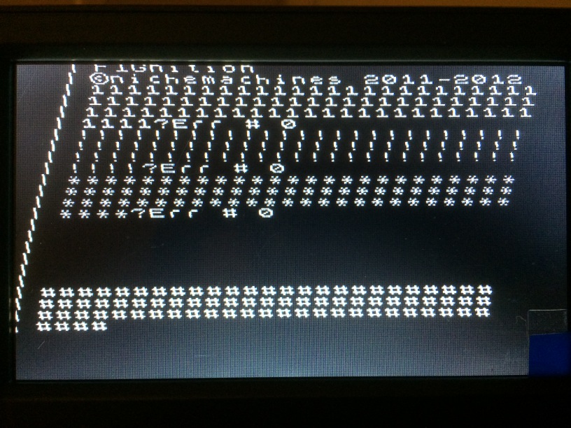
NTSC horizontal tracking issue?

fig8r
Hi All,
I tried Fignition with a small 4" TFT LCD such as used
for car rear view display, and see that the horizontal lines are skewed
progressively towards the top-right (see pictures below). The same LCD
shows other inputs correctly.
It might have to do with imperfect
horizontal sync timing. E.g. this LCD may count on certain standard
rate, whereas other displays/TVs may be more tolerant and always adjust
the timing based on actual horizontal sync pulses.
The LCD
supports PAL and NTSC. I then connected Fignition via multi-system
converting VCR where input and output systems can be set. As show in the
pictures, when the input is set to NTSC, the picture is skewed just
like with direct connection. When switching to NTSC.43 input, it shows
straight picture.
On Fignition there's an NTSC firmware. I didn't see such effect on other displays. So the questions I have:
(1)
What is the difference between NTSC and NTSC32 firmware? I don't
remember which one is installed (maybe last time it was installed there
was just one). Should I try both NTSC and NTSC32?
(2) Would it be
feasible to have the sync/video parameters configurable, e.g. memory
locations, which could be set from Forth, in order to accommodate
variations in video displays? Or it would slow down the system?


Regards,
Oleg
Other references:
Timing differences between NTSC and PAL
https://groups.google.com/d/msg/fignition/Tyh4eW72m8A/uGG3v1MRznsJ
Video bouncing problems
https://groups.google.com/d/topic/fignition/wwDaJGMopqg
PAL Video
https://groups.google.com/d/topic/fignition/BTgtTN801OA
LCD Pal Video Fix
https://groups.google.com/d/topic/fignition/2jDNXbzEhmw

Julian Skidmore
--
You received this message because you are subscribed to the Google Groups "FIGnition" group.
To unsubscribe from this group and stop receiving emails from it, send an email to fignition+...@googlegroups.com.
For more options, visit https://groups.google.com/d/optout.
The DIY 8-bit computer from nichemachines™
Julian Skidmore
fig8r
Thank you for the details and suggestions.
Re NTSC.43, I also looked it up, that it's color information related only. The reason it shows straight picture could be converter specific: that if input and output do not match, it may force the actual conversion circuit rather than a pass-through. And the output of the conversion may in fact be with more strict NTSC sync timing.
As I understand, you are encouraging to tweak the horizontal sync parameters in a custom build of the firmware. That's an interesting approach. At least it would establish if that's possible of it has any effect to even consider a possible customization or alternatively a custom build template that folks with varying displays may try.
> Line scanning on NTSC for FIGnition should be 63.6µs (159 cycles at 2.5MHz), which I understand ought to be close enough to 63.5µs for a scan line for it to work.
If I get to make changes in the source, which file and which lines would correspond to horizontal sync, and in what value ranges (estimated)? It could be different parameters or possibly even one of the calculation formulas below.
While I am doing this, I also noticed that the top margin could be expanded, as you can see. So that's another parameter. Perhaps:
#define kFrameVideoMarginTopScans ((kFrameFieldScans-kFrameVideoScans-kFrameKeyPromptScans)/2) + 2
Possible lines for horizontal sync timing:
...
#ifdef __VideoGenNTSC__
// only 20MHz supported.
#if F_CPU == 20000000
#define kHSyncScan (159-1)
#define kHSyncPulse4us (12-1)
#define kHSyncScanShort (80-1)
#define kHSyncPulse2us (6-1)
...
/**
* A single NTSC frame is 262 lines ( int(525/2)).
* 14/2 = 7 lines are used for VSync, leaving 255 for the full frame.
* 192 scans are used for the image leaving 255-192 = 31 for top margin
* and 255-topMargin-192 for the bottom margin.
**/
#define kFrameSyncPreEqual ((kHSyncScanShort+1)*5)
#define kFrameSyncEqual ((kHSyncScanShort+1)*5)
#define kFrameSyncPostEqual ((kHSyncScanShort+1)*4)
...
Julian Skidmore
--
You received this message because you are subscribed to the Google Groups "FIGnition" group.
To unsubscribe from this group and stop receiving emails from it, send an email to fignition+...@googlegroups.com.
For more options, visit https://groups.google.com/d/optout.
fig8r
Furthermore, if you look closely at the first image above, the vertical line shifting to the right occurs every 4 lines by 1 pixel. So the math adds up.
What I am thinking is would it be possible to adjust the counter TOP by 1 every 4 lines? It would work just like leap years.
Please let me know if I am totally off track.
fig8r
case kFrameSyncScanLine:
#ifdef __SUPPORT_BM_MODE_ ... #endif
OCR1A += kFrameVideoMarginLeft; // get ready for next line.
#ifdef __VideoGenNTSC__
if ((gScanRow & 3) == 0) OCR1A++; // every 4 lines (mod 4)
#endif
Julian Skidmore
--
You received this message because you are subscribed to the Google Groups "FIGnition" group.
To unsubscribe from this group and stop receiving emails from it, send an email to fignition+...@googlegroups.com.
For more options, visit https://groups.google.com/d/optout.
fig8r
Hi Julz,
You are right, just changing one timer causes complete loss of tracking. The linked changes to OCR1A and OCR2A hold the picture. But results are interesting, which I wanted to share before further analysis. Below are various outcomes, where +1 or -1 means changes to both timers as in the code snippet in your email. I the affected lines are also varied (every 4, 8, top or bottom 7). These are numbers which produce more or less straight columns, others, e.g. top/bottom 6 or 8 would accumulate a skew like in the original image.
On a CRT TV, where all unamended lines produce straight columns anyway, the corrective skewed lines produce equal and opposite shift in the subsequent uncorrected lines (e.g. 7 top/bottom lines of forced +1 will be followed by ~5 lines with -1 shifted automatically; whereas every 4/8 +1 will produce a column of sigmoids on the margin line as opposed to "slashes" on LCD).It was also observed that, on a CRT TV, the top line is cut off in any case (even the normal firmware), whereas under the bottom prompt block, there's empty space of 1.5-2 character rows (similar to the last picture). So while we are doing this, maybe it is possible to move the picture about 8 lines below (increase the top margin). I haven't figured how to increase the top margin. I guess it's essentially drawing a few blank lines at the top, similar to bottom prompt. I believe it would conform to TV standards, that there should be a margin around the frame.
Looks like in some such LCDs, the scan lag/gain is accumulated and distributed over the whole frame. So my thinking is if a top margin would be added, it might be used to perform the +1 shifting of its lines, so it's not visible, but will have the straightening effect for the rest of the frame.
if ((gScanRow & 3) == 0) ... +1 // inc every 4 lines

if ((gScanRow & 7) == 0) ... +1 // // inc every 8 lines

if ((gScanRow & 7) == 0) ... -1 // // dec every 8 lines
if (gScanRow < 7) ... -1 // dec top 7 lines


Oleg
Julian Skidmore
--
You received this message because you are subscribed to the Google Groups "FIGnition" group.
To unsubscribe from this group and stop receiving emails from it, send an email to fignition+...@googlegroups.com.
For more options, visit https://groups.google.com/d/optout.
fig8r
Carrying on... So based on scan line time experiments, I think the timing may not be an issue: there's an effect of averaging a shift among multiple lines or the whole frame. At the same time, when the signal goes through a more robust receiver, it works fine.
A new idea, is that the issue is possibly with the quality of the signal. Could it be that the scan line sync is not registered properly by the receiver? That might explain why it cannot anchor on the line start and averages the shift.
So I did some experimenting with an oscilloscope. To start I captured some waveforms from a standard TV equipment -- a standard resolution camcorder, which shows correctly on the LCD display. The waveform is very distinctly recognizable NTSC scan line: you can see the sync dip, the burst porch, the video etc. And it is very stable and easy to lock into. Then I tried to capture Fignition signal. Hmmm, with the same scope settings it is not captured. By changing the settings, trying x10 etc., with some difficulty it is possible to see some waveform, but does not look like a video signal.
So is it possible that Fignition video is somewhat different from standard, e.g. weaker, different amplitude, susceptible to interference, less defined (too much smoothed by capacitance or other low pass filtering)? Would it make sense to try to amplify it, e.g. with an op-amp or send through some sort of (multilevel) buffer to make more defined?
It would be interesting if someone else could capture Fignition video to compare and exclude the possibility of scope artifacts.
Fignition video

Standard video:

fig8r
The previous experiment was probably influenced by mains / power supply interference. So the following sample was taken by separating the two video signal lines back to their digital form and using a better scope. For comparison, below is the NTSC standard vertical syncing profile.
What strikes in comparison is that the number of half-width (short) pulses for Pre-EQ / Vertical Sync / Post-EQ are different. I wonder if that could be the reason of possible compatibility issue with some displays, and if it is worth or possible trying to correct them in firmware, just like we did with the horizontal sync pulse?
FIGnition:

NTSC Standard RS-170A:
fig8r
By varying the following parameters, it was possible to achieve the NTSC spec vertical sync short pulse counts (the last image below). The final values are:
#define kFrameSyncEqual ((kHSyncScanShort+1)*11/2)
But it did not affect the picture on the LCD display -- still skewed.
I wonder if the video generates both the Odd and Even fields or just the Odd field (which is illustrated here)?
The following parameters were varied. Some combinations produced no picture at all. Looks like certain pulse parity matters.
Also since it required 0.5 of short pulse to adjust the final set of parameters, yet shifting in whole pulse distances, there might be a lag between the main and pulse counters.
#define kFrameSyncPreEqual ((kHSyncScanShort+1)*(5+Pre))
#define kFrameSyncEqual ((kHSyncScanShort+1)*(5+Equ))
#define kFrameSyncPostEqual ((kHSyncScanShort+1)*4)) /* unchanged */
Original FIGnition firmware: Pre - has 3 less pulses, Equ has 1 less pulse.

- Pre +3, Equ +1 - no picture, Post has 1 extra pulse:

- Pre +3, Equ +0 - no picture, Equ has 1 less pulse

- Pre +3, Equ +0.5 - picture! correct # of pulses in all segments
