Re: CNC Router

Matthew Gidel
On Tuesday, July 14, 2015 at 12:47:07 PM UTC-5, Chris Johnson wrote:
We won't know until we see where we are after tonight. Hope to get the recuts done to the tabletop and side lifted pieces. From there it is reassembling it all. We might need to have you disassemble the X-carriage and work on widening it. The new bolts are there, but we need spacers built/printed/bought. They should be 20mm long and 5mm internal holeChris
On Tuesday, July 14, 2015 at 12:16:02 PM UTC-5, Matthew Gidel wrote:I am thinking of going in on Wednesday if there is anything I can do.
On Wednesday, May 6, 2015 at 6:48:26 PM UTC-5, Mike Longnecker wrote:So now that we have SheetCAM, will this work to generate toolpaths for the Mogul in the back, and what is left to get that working? I have a really cool project I’d like to do that requires a CNC router, and I’m sure others would love to use it at some point. I’m up for helping to get it running.
Mike Longnecker

Chris Johnson
Chris Johnson

Jeffrey Ollie
--
You received this message because you are subscribed to the Google Groups "Area515 - Des Moines Maker Space" group.
To unsubscribe from this group and stop receiving emails from it, send an email to dsmhackerspac...@googlegroups.com.
For more options, visit https://groups.google.com/d/optout.
--

David Champion
Jeffrey Ollie
I'm pretty sure that I have everything I need already.

Util designs
Sent from my iPhone
Matthew Gidel

Don Cady
Don Cady

Matt Stanton
Sent from my <advertisement for annoying mobile product />
Don Cady
We didn't end up printing them, as Jeffrey found a cache of them in the back of his car.., but I'll have to remember that for the future.
ps. I'm lovin' that sig line.
Don
Jeffrey Ollie
--
Chris Johnson
Jeffrey Ollie
I need one more bracket, and I need to print out the pieces for the extruder design I found on the delta users list. Most of those pieces are pretty small so that should go quickly.
Chris Johnson

Bailey Mader
Annoying, but vital, request. Could you guys send me a couple pics of you working on the CNC, some progress shots, or even a short video so we can post something on our social media? I know you're working hard on it, I want others to see that too!
Chris Johnson
- The X-carriage needs to be split and widened with the new spacers and longer bolts.
- The wiring needs to be reinstalled through the X-axis and terminated
- The entire X,Y gantry assembly needs to be put back together so we can set it in the table top to measure for the Z height pads to be cut and edged.
- All holes under the T-Trak strips need to enlarged by 2 bit sizes, for side to side adjustment.
- All top pieces and T-Trak need to be assembled, adjusted and screwed down to threaded inserts.
Don Cady
Unfortunately we didn't get any of this finished;
> For those on the CNC rebuild team that want to work on Wednesday night, here is a list of things that need to get done.:
> The X-carriage needs to be split and widened with the new spacers and longer bolts.
This was taken apart and put back together a couple times, and we've determined we need some 8mm spacers and are confused as to how the middle wheels go back in.
>
> The wiring needs to be reinstalled through the X-axis and terminated
Nope. ...but while looking online for pictures of the Mogul was originally put together, I saw many newer revisions they shipped with cable drag chains instead of the grey sheath. We may want one in the future..
>
> The entire X,Y gantry assembly needs to be put back together so we can set it in the table top to measure for the Z height pads to be cut and edged.
Nope.
>
> All holes under the T-Trak strips need to enlarged by 2 bit sizes, for side to side adjustment.
A couple different bits fit what is already there, wasn't sure what size was used originally, didn't want to go _too_ large. Demoralized from the above, I erred on the side of caution and haven't drilled them any larger yet. Result:
Nope.
>
> All top pieces and T-Trak need to be assembled, adjusted and screwed down to threaded inserts.
Nope.
>
> I think I will be there, but depending on a job task, I might miss this one.
>
> Chris
Don
Don Cady
- All holes under the T-Trak strips need to enlarged by 2 bit sizes, for side to side adjustment.
- All top pieces and T-Trak need to be assembled, adjusted and screwed down to threaded inserts.
- The X-carriage needs to be split and widened with the new spacers and longer bolts.
- The wiring needs to be reinstalled through the X-axis and terminated
- The entire X,Y gantry assembly needs to be put back together so we can set it in the table top to measure for the Z height pads to be cut and edged.
Who is available when, so we can make progress on this?
Jeffrey Ollie
--
You received this message because you are subscribed to the Google Groups "Area515 - Des Moines Maker Space" group.
To unsubscribe from this group and stop receiving emails from it, send an email to dsmhackerspac...@googlegroups.com.
For more options, visit https://groups.google.com/d/optout.
--

Ray Scheufler
--

Nabil Hanke
We switched out and got those printed last night.
Ray Scheufler
OK. I guess you guys stayed much later than I thought.
Ray Scheufler
Don Cady
I'm available Sunday, but maybe I could stop in for a bit Sat. too.
I could come down Saturday for a few hours in the afternoon, $DAYJOB has me very busy at the moment.
- The X-carriage needs to be split and widened with the new spacers and longer bolts.
A roll that can be split into 8 or 9 or 10mm spacers has been printed. The X carriage needs put back together, then the following two:
- The wiring needs to be reinstalled through the X-axis and terminated
- The entire X,Y gantry assembly needs to be put back together so we can set it in the table top to measure for the Z height pads to be cut and edged.
Nabil Hanke
Yeah, we need to evaluate the options for spacing the y-rails up for more z. The Orange feet for the rails hang off the table a bit much to my liking. But not completely off the table. I'm going to look for some 2x12's I think I've got.
One option I'd go super simple and sacrifice being able to put 48" material onto the table. But it'll be short by an annoying amount.
--
Chris Johnson
Nabil Hanke
That's not the quandary. The feet need to point out from the table, but in doing that they hang past the edge and don't have much table left to mount to.
Chris Johnson
Don Cady
Chris Johnson
Nabil Hanke
I do recall that discussion now. In that case, we are ready to stack up the spacers for the Y rails and start assembling.
Chris Johnson
tomorrow? I can bring the edging and iron back down and we can cut and edge the remaining pieces.
Don Cady
OK, I am in the middle of working on cutting extrusion for CBeam3PO. Is anyone working on it tonight or
tomorrow? I can bring the edging and iron back down and we can cut and edge the remaining pieces.
Nabil Hanke
I'm here, doin stuff. Likely will be for most of day.
Chris Johnson
Nabil Hanke
So we moved ahead. Didn't have enough of the chipboard to stack high enough. So we went with the material we had on hand to get the job done. It is quite sturdy.
So tomorrow we can align and adjust and wire and maybe even move axes.

jim kraai
Nabil Hanke
Nabil Hanke
Thanks to Paul for coming down to assist.
We got the basic wiring all in place and connected. And had to find profiles on server etc. No smoke. Works. Basically.
Still need to install y axis limit switches. And touch of pad. And calibrate. And wire in relay for motor. And give the computer a home. And maybe regulate motor speed via software.
But it's alive!! It's ALIVE!!!!
I plan to be at the space tomorrow if anyone is interested in helping. It would be very cool to have it marginally operable on Tuesday.
Chris Johnson

beernutz
Great work guys! Wish I could be there. I would trade Area 515 for the hospital any time. Hoping to stay out this time. In case you are wondering, the body doesn't run well at 80 over 50 and no fluids. Hoping to make it Tuesday and at least cheer you on.Chris
Don Cady
>
> Great work guys! Wish I could be there. I would trade Area 515 for the hospital any time. Hoping to stay out this time. In case you are wondering, the body doesn't run well at 80 over 50 and no fluids.
This was blood pressure?
jim kraai
>
> Great work guys! Wish I could be there. I would trade Area 515 for the hospital any time. Hoping to stay out this time. In case you are wondering, the body doesn't run well at 80 over 50 and no fluids.This was blood pressure?
--
Matthew Gidel

Tim-S
"and no fluids"
...
...
Found your problem. I recommend injecting an IV bag of gear oil. Seriously though, I hope are (and remain!) better.
Nabil Hanke
Chase a quart of Slick 50 with a NOS energy drink. You'll be right as rain.
Nabil Hanke
Don and I got profile figured out and more mounting done. We need to figure out done things with Linux cnc for homing behaviour and touch off pad.
Wired up y axis end stop. It works. Need to hunt down another stop switch for the back side.

Paul L. Mohr
I have a micro switch with the proper form factor, mounting holes, and actuation. I will bring it with tonight
Don Cady
Bonus items- replace the x stop switches with some _with_ whiskers. Maybe even long whiskers, so we can bend them how we want. (for those following at home: the producer of this kit stupidly clipped the whisker tabs off the x carriage switches, which risks slamming said carriage into the wheels on the y rail)
Nabil Hanke
Update for Tuesday open house progress.
Installed switch provided by Paul. We now have upper and lower limit switches on both x and y axes. Played around with using end stops as homes. But I'm skeptical that they are actually good reference points. So for now it doesn't search for home. Wherever it is when you home it is home.
Z still has no limits, lower limit is going to be the touch off pad. We may yet need to install an upper limit switch, despite my initial thoughts to the contrary. So we will need some more switches.
We are limited to only five inputs, so instead of eating up four of them with discrete upper and lower limits for x & y, we wired each respective axis switches in parallel. To do so required changing them from normally closed to normally open. But we now currently are using only two of the five inputs.
Also Don and I noodled out the enable pin for the spindle motor. It is open collector on the high side of the 24v rail. However, out relay box maxes out at 12v input. So we need to level shift it. Our attempts last night were less than encouraging. The relay specs a 3-12v & 3-30ma input. So we did a voltage divider with a 2.2k and 1k series resistors. But instead of the 7 volts expected, we got 2.7. And our 24v input read 9. Then we realized it was well after midnight and stopped.
Paul L. Mohr
https://en.wikipedia.org/wiki/Kirchhoff's_circuit_laws
https://en.wikipedia.org/wiki/Th%C3%A9venin's_theorem
Tell me when you will be there and I will do the science :) and we will make it go.
I have several variable regulators and that is more efficient for voltage shift.
Input and output impedance mismatch , drive current I suspect to be 20ma, so about 1k output impedance
The math says that output impedance would be 6k for 0 impedance input if your measurements are correct or more likely, input impedance is 1k and output impedance is more than 1k which would fit with common standards of industrial 20 miliamp loop type circuits
Variable regulator is the way to go, LM317
https://en.wikipedia.org/wiki/LM317
Ray Scheufler
Paul L. Mohr
Don Cady
If you're saying there should be an _additional_ 4v drop, this makes partial sense (within my limited comprehension), as there was a 4.7k on the board (SMD with resistor code 472) we thought could be between the incoming 24v and the output pin. But the output pin still read near* 24v without the voltage divider. Confused, and considered our thinking might be clouded by tiredness, looked at clock and.... <- you can chronologically put that between Nabil's second-to-last and last sentences. :)
*I don't remember exact values.
We should read what the supposed-to-be 24v supply is before it goes to the board to see what it really is, compare with after to see if the 4.7K accounts for the difference.
Don
Paul L. Mohr
Since not everybody is EE or CE, I will make a diagram.
+24v->>---4.7K--.-------------x------y-------.-------LED---1K-->>-GND
OC(out) SSR(in)
This is what I see from your description. The output drive is pulled up to 24v through a 4.7K resistor and shorted to ground with an OC driver
which would be connected to the input of the solid state relay, which has an internal 1k current limiting resistor. If you put a 2.2k resistor at x
and a 1k resistor to ground at y then the voltages would be approximately what you measured.
This is the model that seems to fit what you are saying, but without looking at the stuff and measuring, it is merely my take on what is happening.
It would make sense that if the (OC out) was connected to (SSR in), the voltage measured at (SSR in) would be about 4V and would turn it on.
I -think- this is what Ray is saying also.
Surgeon General's Warning: In the state of Confusion, this product may produce magic smoke.
Chris Johnson
Nabil Hanke
That's a great write-up.
Here is I little bit to get everyone going for the router:
Don Cady
Except the SSR in is where it read 2.7v, hence our initial confusion.
Nabil, when were you thinking of taking a crack at it again?
[keep in mind compressor pipe volunteers will be around Fri night and may want access to the hole]
Don
Ray Scheufler
I will be around this evening and will likely poke at it.
Ray Scheufler
Nabil Hanke
Ray poked. My nocturnal assessment was wrong. The transistor connects to ground. The 24v measurement was normal leakage through a snubber diode to protect against spikes if you use it to drive a relay coil directly. Anyway, we tested and then wired and succeeded in switching power to the motor via computer control.
We then focused our attention on the touch off pad. Ultimately installed a panel mount 1/4" headphone jack in the x carriage for the touch off pad. So it is removable with a confident connection.
Very good progress indeed.
Paul L. Mohr
Nabil, I have some of those tiny screw terminal screws and will bring them with the next time I am there. I keep a disk drive magnet inside my cyclonic vacuum cleaner and it collects all kinds of stuff I didn't know I dropped :)
I will try to make it to help with pipe removal tonight.
The result (CNC router) operates as it should and is wired properly IMHO, however I did go back and refresh myself on reverse diode currents. A typical reverse current of a diode is in the micro ampere range and cannot be responsible for the measured ma currents in a test circuit. I would -guess- that the confusion comes from the indicator LEDs that are part of that circuit also. Also the SSR is a real Relay and not a solid state switch ( which are more expensive). I always enjoy learning new things and the relationship of the thermal electron leakage in diodes as it relates to the nature of electron flow in thermocouples was an interesting connection. It was only recently that I truly grokked the fact that conduction band electrons in metals are the carriers of thermal diffusion.
I still say there is an equivalent resistance to 24v of around 5k somewhere in the drive circuit. It would be interesting to look at a schematic of the parallel port stepper driver device.
Nabil Hanke
I haven't found a good schematic for it yet. There are lots of similar devices that have much more documentation. We've been able to stumble through it enough to work that we haven't gone further down the rabbit hole yet.
Nabil Hanke
Just got the y rails fully mounted. And then used a dial indicator to probe the corners. It's not perfect yet, but close. In probing the whole bed space, total deviation is about .060".
I'm gonna dive into setting offsets for placing work pieces.
Now would be a good time to bring sacrificial boards for holding work pieces.
Plans have been discussed regarding dust control. Full height floor to ceiling curtains sound like a good way to quarantine. But we will need to get a sufficient dust collector going as well.
Paul Mohr
Nabil Hanke
Right now, the router will do a 41" x 41" area.
Does anyone have a laser pointer we could affix to the router for aligning to work pieces? I found and have implemented a gui button to zero x & y, and they mentioned using a laser pointer to be more precise.
I'm still fumbling with the touch off for z.
Nabil Hanke
So I've wrapped my head around the ladder programming within Linux cnc,I think. The ladder logic has hooks for input and outputs. You define them outside of the ladder editor. And to make a G-code command be your output, that's in a different file than the one defining it's ladder association. And the addressing of said G-code command is relative to its sequence in the text file- that is, so that association can break easily and do bad things.
But anyway, the cookie cutter I downloaded gives a gui button to set tool tip offset. That's cool. But next I need to build a similar function to set bed surface height relative to tool tip.
At that point, I'll be much more confident with saying it's time to put the machine to work.
Don Cady
So I've wrapped my head around the ladder programming within Linux cnc,I think. The ladder logic has hooks for input and outputs. You define them outside of the ladder editor. And to make a G-code command be your output, that's in a different file than the one defining it's ladder association. And the addressing of said G-code command is relative to its sequence in the text file- that is, so that association can break easily and do bad things.
But anyway, the cookie cutter I downloaded gives a gui button to set tool tip offset. That's cool. But next I need to build a similar function to set bed surface height relative to tool tip.
At that point, I'll be much more confident with saying it's time to put the machine to work.
Just got the y rails fully mounted. And then used a dial indicator to probe the corners. It's not perfect yet, but close. In probing the whole bed space, total deviation is about .060".
Nabil Hanke
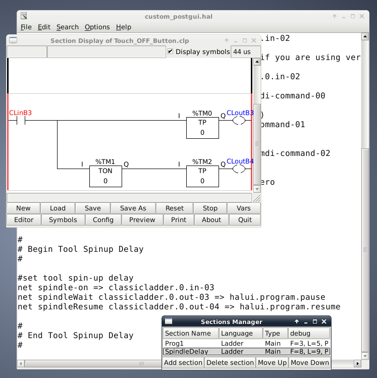
I needed to make three connections: spindle state, and pause and resume requests. These were all done in the custom_postgui.hal file. Those defined what to watch for and what to do.
But the logic of "watching and acting" goes in the ClassicLadder. So I have the "spindle-on" input on the left and two different outputs on the right - halui.program.pause, and halui.program.resume. Between them are three timers that trigger such that the pause command is immediately run, then 8 seconds later the resume command is run. Each of the outputs is fed with its own one-shot timer and the resume is branched with an 8 second timer.
--
Paul Mohr
Great work, I look forward to trying it out. You have really put a lot of time and effort in this.
Nabil Hanke
Continued progress:
Made a wall mount arm for monitor & mounted
Moved table away from front of machine
Hacked laser pointer to use barrel power jack for 5v negative center tip - needs mounting (will help with part homing)
Still need
Need an extension cable for parallel port, 10' or longer would be great.
Build & mount arm for keyboard.
Adjust x rails to take up slop.
Finish redoing part homing script
Install e-Stop switch
Wednesday night work for anyone to help knock this stuff out and get routing?