Looking for a Mechanical engineer to join the Ardupilot/PX4 Hardware team

Philip Rowse
As we ramp up the Pixhawk 2 effort, there is a need for some mechanical work. Pixhawk 2 is more than an EE effort, and to maximise its abilities, we really need someone, or a group who have the FEA skills to model the effects of vibration on the system, and to assist in making some choices in the mechanical aspect of the design.
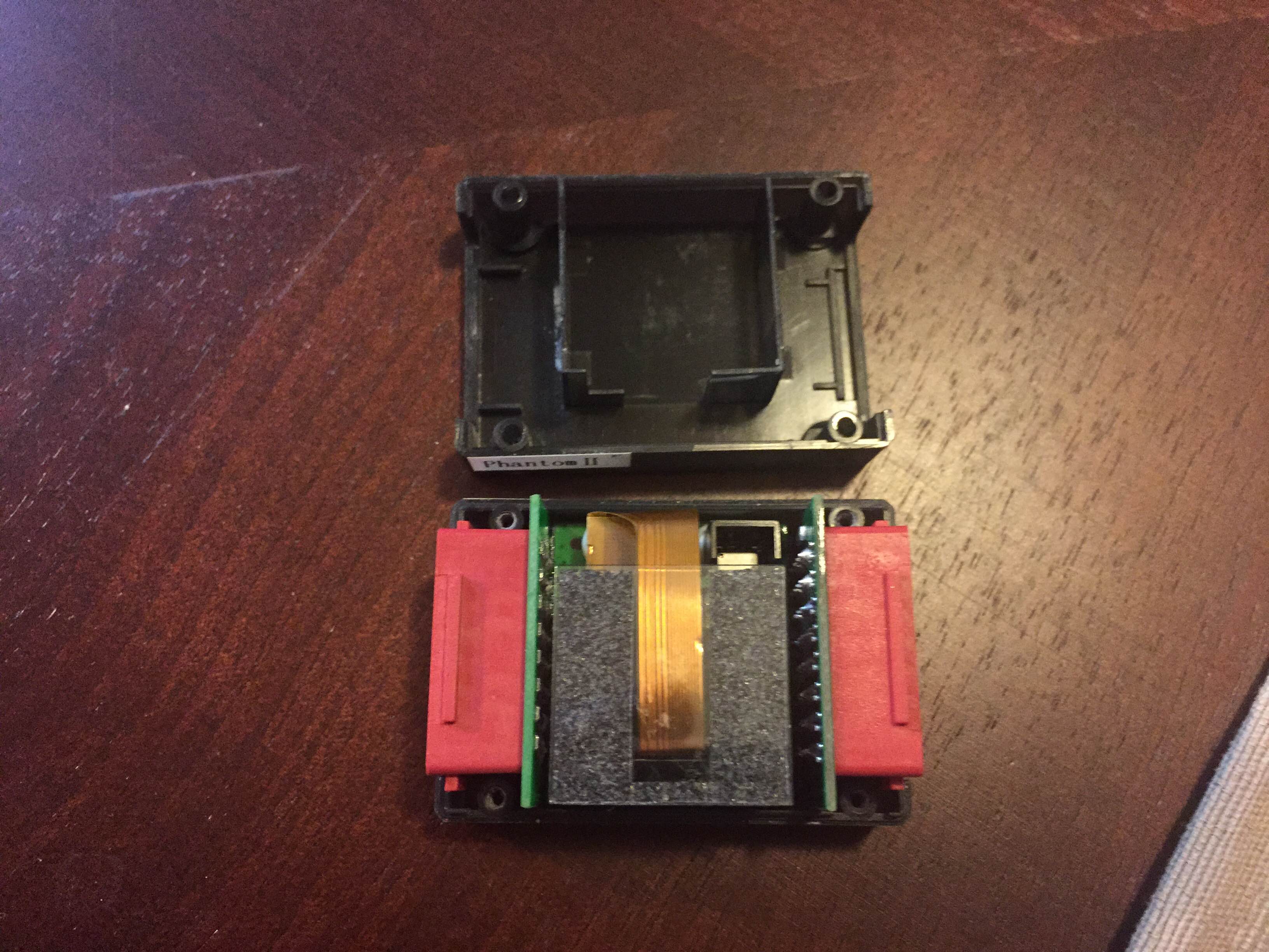
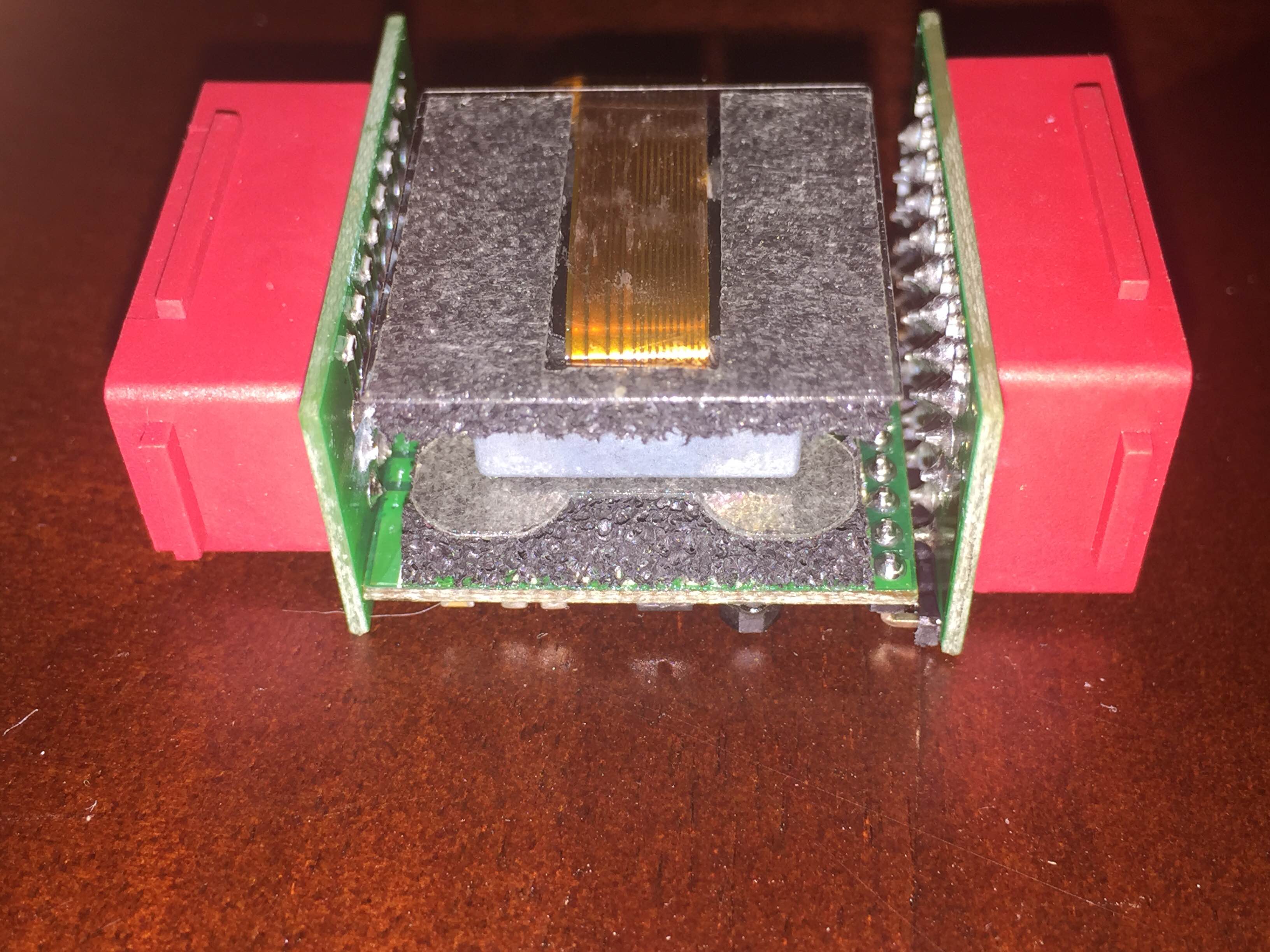
Basically, I need assistance in verifying the Isolation system on the stand alone version of this board.
The current setup is optimized for Solo, this may or may not be suitable for the bulk of other use cases in the market.
We also need someone who is good at injection moulded plastics etc.
Philip

Nikolay Arsov
There is such a guru, but he's living here in Smolyan, Bulgaria. He's a real guru in mold and stamp design and is using SolidWorks and Proengineer.
He's also a guru in injection molding. He's a mechanical engineer with > 35 years experiance. Currently he's designing molds and tools for Phoenix Contact.
His name is Georgy Kasabadjakov. You can freely contact him at georgi.ka...@gmail.com
Best regards
Nick

Philip Rowse
is he interested in Open hardware?
Philip
Sent from my iPhone
Thanks Nick!
is he interested in Open hardware?
--
You received this message because you are subscribed to a topic in the Google Groups "drones-discuss" group.
To unsubscribe from this topic, visit https://groups.google.com/d/topic/drones-discuss/tO8_hhSH_Jo/unsubscribe.
To unsubscribe from this group and all its topics, send an email to drones-discus...@googlegroups.com.
For more options, visit https://groups.google.com/d/optout.

David Kraus
Dne sobota 7. listopadu 2015 7:43:32 UTC+1 Philip Rowse napsal(a):

Inverted CNC
You received this message because you are subscribed to the Google Groups "drones-discuss" group.
To unsubscribe from this group and stop receiving emails from it, send an email to drones-discus...@googlegroups.com.
For more options, visit https://groups.google.com/d/optout.
--
Sent from Gmail Mobile

Jiro Hattori
Do we really need FEA to mount IMU and main flight controller?

Jonathan Challinger
Hi, I am also mechanical engineer, some sort;-)
Do we really need FEA to mount IMU and main flight controller?
Jiro Hattori
I do not know the actual chip on Pixhawk 2, but should have some noise level.
Jonathan Challinger
Yes, we need some mechanical band pass filter that should be better than good old 3M sponge tape.
I do not know the actual chip on Pixhawk 2, but should have some noise level.

aitor...@gmail.com
I'm mechanical designer, skilled in designing parts for plastic injection manufacturing processes, and FEA analysis. Have also demonstrable experience in designing multirotors and many other professional and also DIY gadgets, etc.
If I understand correctly, the goal is to design the box containing the PCB and its damping system. If not, forget the following :)
In my opinion, it doesn't exist the universal solution you are looking for.
Your main goal would be to determine the resonance frequency of the firsts main vibration modes to which the pcb is subjected. The quad's main vibration source are the motors. Leaving aside the starting phase of the motors, the main work regime (r.p.m -> frequency source) of the motors will be KV and also voltage dependent. In addition, you have to consider the arms size that hold the motors and the material that these are made of (FEA program will need it to calculate the structure's vibration modes frequencies)
Furthermore, in the most conservative case (assuming you have a particular type of engine, working at a certain voltage, hovering in a given amount of throttle and a mechanical structure with a well known stiffness...), for an accurate FEA analysis, and supposing that you want to use some hyperelastic material for pcb damping, you should be able to calculate the Mooney-Rivlin Constants of this material (needed for most FEA programs when it comes to nonlinear analysis of hyperelastic materials) and this will be possible only in the assumption you have a complete material characterization and usually you won't have this.
Summarizing, I think there is not a universal solution for this, and the attempts to find a good solution involving FEA analysis won't throw an accurate solution. There are too many degrees of freedom out of your your control in this problem: KV, Voltage, structure stiffness, damping material...
I suggest you to use a well known damping material, filtering the most sensitive frequencies for the different IC in the pcb and... that is. Vibration control rests in frame designer's side more than in yours.
Best regards,
Andrés
Jonathan Challinger
I'd have to agree there to a point. You might design a solution for a 450-size multicopter and have it resonate at the lower frequencies that a larger tradheli vibrates at.
However, we can probably do something that handles the 95% case which means attenuating frequencies higher than something like 50hz.
--
Philip
Phil
You received this message because you are subscribed to a topic in the Google Groups "drones-discuss" group.
To unsubscribe from this topic, visit https://groups.google.com/d/topic/drones-discuss/tO8_hhSH_Jo/unsubscribe.
To unsubscribe from this group and all its topics, send an email to drones-discus...@googlegroups.com.

john...@gmail.com
Jonathan Challinger
The problem is not aliasing but clipping. We need to design the mount to attenuate vibrations such that they never peak higher than 16g.
Looking at the sensor characteristics and Nyquist ect, could you not turn the question around and design the sensor cage dampening to prevent frequencies that will cause aliasing? The goal is not to prevent any and all vibrations from the copter, but to make sure the sensors data is usable.
Philip Rowse
Regardless as to why... being able to understand the hardware before prototyping is just a basic function of modern day engineering. FEA tools are so simple to use these days.... but getting access to them is not.

Andy Little
aitor...@gmail.com
Assuming that frame stiffness is high enough (which usually meets when it comes to quadcopter's assemblage, there is not loose parts, etc), its resonance frequency would be much more higher than this. In this case, frame's resonance frequency won't see motor's vibration: We can ignore the frame and we can focus in isolating the pcb from frequencies from ~20 to 300 Hz (very nice bass frequencies :))
Important: If you place baro in pcb's bottom side, you should isolate this from damping material: placing baro in direct contact with damping material would be the same that placing this direct over a subwoofer! :)
Regards,
Andrés
john...@gmail.com
aitor...@gmail.com

Robert Lefebvre
Jonathan: Consider a Spherical Cow... ;)
--
Robert Lefebvre
aitor...@gmail.com
El lunes, 9 de noviembre de 2015, 14:29:47 (UTC+1), robert.lefebvre escribió:
It's a really bad assumption that the frames are stiff enough that they don't need to be considered.
As I said in my first post: frame's construction (in all its infinite forms and possibilities) is out of your control, so I'm just trying to set an approaching to the problem in the most ideal conditions. If helps.
Regards
Tom Pittenger
--

Ryan Linderman
If you want to take the mechanical engineering of this system to the next level then there would also need to be a fair bit of testing to vet out the new solution to the old so we could improve the models for the next design round. We would also need to define a 95% standard air frame configuration and vibration profile to use with future models. This implies we know the vibration generated by a "standard" motor and frame configuration quite well. If every time we start a new project we change the input parameters it will be very hard to know if the results are improving.
Probably the easiest way to start would be to impose a vibration profile to the pixhawk board enclosure and ignore the rest of the system -- this is where a standard vibration profile that is somewhat representative is important. We could then try different suspension systems between board and enclosure to gauge how effectively we are damping vibration. It's up to the end user and their combination of airframe and motor to control what vibration gets to the pixhawk enclosure. Future designs modeled with the same standard vibration profile on the enclosure would allow an indication of how much things are improving.
I can imagine there is a simple spring feature that is molded into the enclosure that allows the board to float on the spring mechanically -- which wouldn't allow some frequencies to propagate to the board. When cables are plugged in, the springs deflect to a hard stop to allow enough force to insert the cable. One would have to be careful that cable tension is not so great that is pulls the board to the hard stop after assembly.
I have access to an under utilized Ansys Mechancial license as well as Solidworks if you want to try some simple runs. The 3D CAD would need to be cleaned up to remove lots of fine details like fillets and every single board component and tiny feature (again we need a kind of standardized simple board with basic mass and stiffness).
-Ryan
Robert Lefebvre
Inverted CNC
--
Sent from Gmail Mobile
Robert Lefebvre
Inverted CNC
Robert Lefebvre
john...@gmail.com
http://diydrones.com/profiles/blogs/zerouav-ys-x4-teardown
To unsubscribe from this group and stop receiving emails from it, send an email to drones-discuss+unsubscribe@googlegroups.com.
--
You received this message because you are subscribed to the Google Groups "drones-discuss" group.
To unsubscribe from this group and stop receiving emails from it, send an email to drones-discuss+unsubscribe@googlegroups.com.
--
You received this message because you are subscribed to the Google Groups "drones-discuss" group.
To unsubscribe from this group and stop receiving emails from it, send an email to drones-discuss+unsubscribe@googlegroups.com.
For more options, visit https://groups.google.com/d/optout.
--
Sent from Gmail Mobile
--
You received this message because you are subscribed to the Google Groups "drones-discuss" group.
To unsubscribe from this group and stop receiving emails from it, send an email to drones-discuss+unsubscribe@googlegroups.com.
--
You received this message because you are subscribed to the Google Groups "drones-discuss" group.
To unsubscribe from this group and stop receiving emails from it, send an email to drones-discuss+unsubscribe@googlegroups.com.
For more options, visit https://groups.google.com/d/optout.
--
Sent from Gmail Mobile
Jiro Hattori
Firstly, we need lager mass in CG.
Secondary, we need springs and dumpers for any directional vibrations.
Most of the failure on DIY flight controller mounting system may be thinking of one directional vibration input.

Inverted CNC
--
You received this message because you are subscribed to the Google Groups "drones-discuss" group.
To unsubscribe from this group and stop receiving emails from it, send an email to drones-discus...@googlegroups.com.
For more options, visit https://groups.google.com/d/optout.
Paul Riseborough
Paul Riseborough
Robert Lefebvre
--
Tom Pittenger

a a
For the last 10 years I study vibrations generated by wind turbines, wind farms, infrasounds, brain waves, FFT,
vizualize vibrations in 2D/3D, study seismography and infrasounds generated by vibrating wind towers, transmitted through the ground kms away.
I go to Vienna Conference on Seismography with my papers.
Develop 100 seismographic sensors array, build sonars, georadars.
Built small wind tunnels to test drones indoor.
Since vibrations can be visualized I am open for any cooperation.
I need budget to buy hardware to build stand for tests, install sensors, board and more.
Just let me know what hardware should be tested and what is a source of vibrations in the tests, full frequency spectrum (rpm) and number of vibrators.
darius
mant...@gmail.com
Ryan Linderman
However I'm pretty new to drone engineering and am interested in studying the vibration modes in my Iris+ airframe with Pixhawk controller.
What is the best way to access the IMU sensor data? I'm assuming we will have to run it through an FFT filter to identify intensity of different modes.
Thanks,
Ryan
On Thursday, November 5, 2015 at 7:36:49 PM UTC-8, Philip Rowse wrote:
Hi all
As we ramp up the Pixhawk 2 effort, there is a need for some mechanical work. Pixhawk 2 is more than an EE effort, and to maximise its abilities, we really need someone, or a group who have the FEA skills to model the effects of vibration on the system, and to assist in making some choices in the mechanical aspect of the design.
Basically, I need assistance in verifying the Isolation system on the stand alone version of this board.
The current setup is optimized for Solo, this may or may not be suitable for the bulk of other use cases in the market.
We also need someone who is good at injection moulded plastics etc.Please contact me via this list if you have any of these skills, or you know someone that does.Thankyou
Philip

Randy Mackay
Ryan,
In the log bitmask it’s possible to set the IMU logging to RAW (i.e. check the IMU_RAW checkbox).
This should output the raw data from the IMUs at a ridiculously high rate (1kHz for mpu6k, 1.6kHz for lsm303d) and the mission planner has a built in FFT viewer (I forget where it’s hidden). Make sure you have a high quality SD card!
-Randy
philip
Tridge can weigh in here… but the quality of the card is quite specific, some of the expensive cards actually don’t work as well for high speed logging I believe….