yet another VL53L0X board
450 views
Skip to first unread message

googlegroups
Dec 8, 2016, 1:32:49 AM12/8/16
to diyrovers
Hey folks:
Just an FYI about a design I did using the VL53L0X parts for an FRC (First Robotics Competition) robot. The build season does not start until Jan 7, but hopefully we can integrate these into the autonomous driving part of the event.
In default mode they are good to about 1200mm (which is plenty for this application), and it simplified the interface code a lot. They have a 25-degree
field-of-view, so up to eight of them can be mounted around the
perimeter of the robot (front/rear/left/right plus four corners with a
45-degree mount). Each sensor will provide a range from 20 to 1200mm at
a rate of 25 times a second. The pods daisy-chain with with 6P6C modular cables.
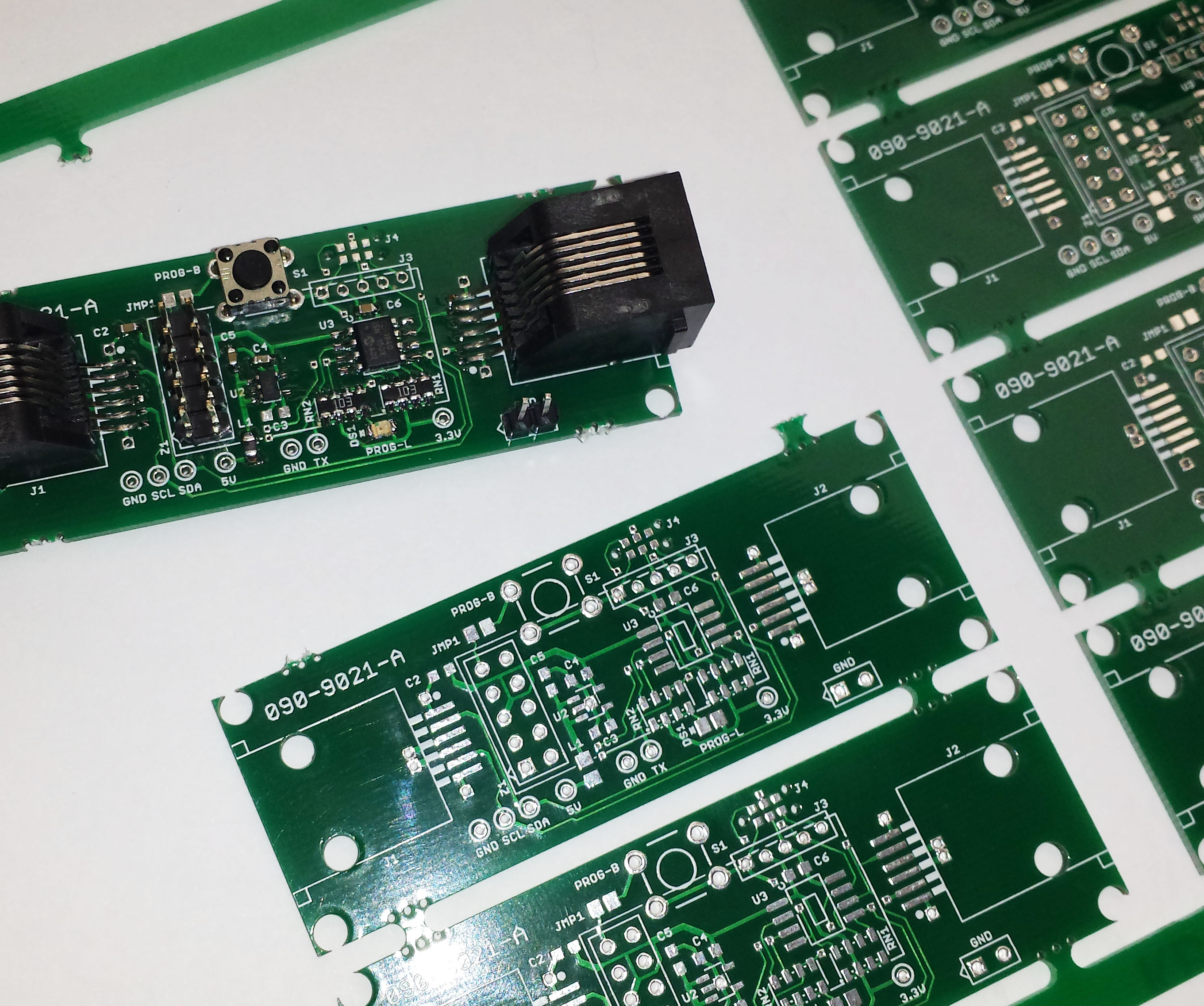
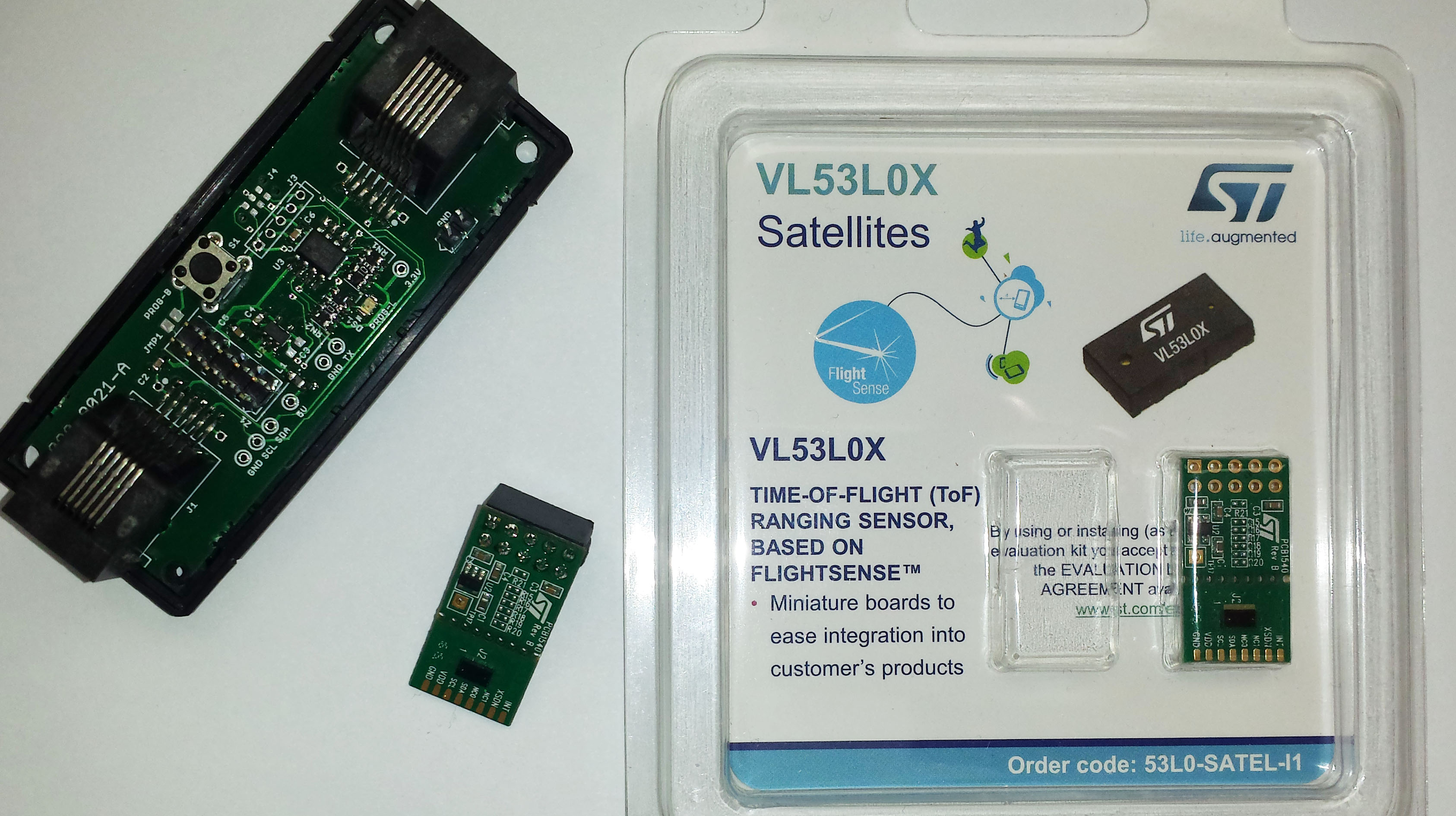
Am just using the ST satellite boards, as you get two for about $18, and it was not worth the hassle to mount the tiny chips (which are two for about $12). The satellite boards mount to a small pcb I designed to fit into a dongle case. This board has a
little PIC micro which handles the details of its attached sensor, and
has a pushbutton/light that lets you easily set each pod to a different
I2C address (and save it in eeprom, which the lidar chip does not do). Also, the satellite boards are said to only be happy as the sole device on the bus, so a $1 PIC lets me keep everything clean: an I2C master port to the lidar, and an I2C slave port on the modular daisy-chain with a programmable address.
The lidar chain plugs into another board I did, teensyRIO, which mounts in an expansion port on the robot's control system (roboRIO). A teensy polls the lidar chain, and sends the aggregate data to the main robot code. The kids just get updated range numbers to use in the main java code for the robot, with all of the ugly details hidden.
The ST lidar API is a disgusting bloated bit of pig-ware. After digging through the code from pololu (who extracted the essence) and adafruit (who left most of the api intact), I finally figured out that almost none of it was needed for a simple default mode (1200mm). Snips from my PIC code (just lidar stuff):
//--------------------------------------------------------------------------------------------
uint16_t range_mm, prev_range_mm=0, num_bogus_conversions=0; // globals
uint16_t range_mm, prev_range_mm=0, num_bogus_conversions=0; // globals
void main() {
uint8_t i;
// ----- lidar config VL53L0X_DataInit() stuff:
// (just the basic stuff)
//
// --- set 2.8V mode (register 0x89):
i = i2c_master_get_byte(VL53L0X_ADDR, 0x89) | 0x01; // read and set lsb
i2c_master_send_byte(VL53L0X_ADDR, 0x89, i); // then write it back
//
// --- set I2C standard mode:
i2c_master_send_byte(VL53L0X_ADDR, 0x88, 0x00);
//
// (ignoring other api crap done here)
// ----- lidar config VL53L0X_StaticInit() stuff:
//
// (ignoring api crap done here)
// ----- lidar calibration stuff:
//
// (no SPAD calibration)
// (no REF calibration)
// (no OFFSET calibration)
// (no CROSSTALK calibration)
// ----- lidar start continuous back-to-back ranging measurements:
i2c_master_send_byte(VL53L0X_ADDR, VL53L0X_RANGE_START, 0x02);
i2c_master_send_byte(VL53L0X_ADDR, VL53L0X_RANGE_START, 0x02);
while(1) {
// ----- read lidar:
range_mm = read_range_mm();
// so, the max range of this gizmo is about 2000mm, but we will use it in
// "default mode," which is specified to 1200mm (30 ms range timing budget).
// note: 20mm or 8190mm seems to be returned for bogus readings, so trap/limit:
if ( (range_mm <= 20) || (8190 == range_mm) ) {
range_mm = prev_range_mm; // bad reading -- use previous
++num_bogus_conversions; // count the bad readings
}
else if (range_mm > 1200) { // our defined max
range_mm = 1200; // out-of-spec reading -- just limit
++num_bogus_conversions; // but also count the out-of-spec readings
}
else {
prev_range_mm = range_mm; // good reading (hopefully) -- save
num_bogus_conversions = 0;
}
// --- super-simple "calibration" by surlee:
if (range_mm > 400) range_mm -= 50;
else if (range_mm > 160) range_mm -= 40;
else if (range_mm > 100) range_mm -= 35;
else range_mm -= 30;
...
}
...
}
}
//------------------------------------------------------------------------------
/**
Returns a range reading in millimeters.
@param void
@return range in mm (or 0 for timeout, or 20 or 8190 for bogus measurement)
*/
uint16_t read_range_mm(void) {
uint16_t range_mm;
uint8_t timeout = 40; // should be 20-30 ms between continuous conversions
// wait until reading available, or timeout:
while (0 == i2c_master_get_byte(VL53L0X_ADDR, VL53L0X_RESULT_INTR_STATUS) & 0x07) {
if (0 == --timeout) return 0;
delay_ms(1);
}
// get range in mm (just deal with errouneous readings in calling routine).
range_mm = i2c_master_get_word(VL53L0X_ADDR, (VL53L0X_RESULT_RANGE_STATUS + 10));
// clear interrupt (is this needed for a simple polling scheme?):
i2c_master_send_byte(VL53L0X_ADDR, VL53L0X_SYS_INTR_CLR, 0x01);
return range_mm;
}
//------------------------------------------------------------------------------
So, only two things need to be done to init:
- set 2.8V mode (sets IOVDD thresholds; default is 1.8V levels)
- set I2C standard mode (not really sure this needs done either, but it is easy)
A single line starts continuous mode.
The read is easy, and a bit of logic produces two numbers: range in mm, and a count of bogus readings, which can be used as a quality indicator -- if it is 0, then you got a valid reading; over 0 and the previous range is returned so you are kinda close; if it gets over say 10 bogus readings, then range is getting suspect. In practice I saw the bogus count only getting excessive when the distance was over the 1200mm max, but that is also good info.
The returned range numbers were off a bit but consistent, so I added a very simple "cal" routine of my own to correct it quite well. Unsure whether that is the same for different chips, but will find out shortly (I have about 200 of these boards built up and about 8 satellite modules to test).
FYI, Gil

Jon Watte
Dec 8, 2016, 12:06:45 PM12/8/16
to diyrovers
Have you compared these to the Sharp IR range sensors?
I'd be very curious to see what the differences may be!
Sincerely,
jw
Sincerely,
Jon Watte
--
"I find that the harder I work, the more luck I seem to have." -- Thomas Jefferson
--
You received this message because you are subscribed to the Google Groups "diyrovers" group.
To unsubscribe from this group and stop receiving emails from it, send an email to diyrovers+unsubscribe@googlegroups.com.
To post to this group, send email to diyr...@googlegroups.com.
To view this discussion on the web visit https://groups.google.com/d/msgid/diyrovers/20161207233244.611751ebf853c85a377df259b93db888.0fe1d3fb26.wbe%40email24.godaddy.com.
For more options, visit https://groups.google.com/d/optout.

Michael Shimniok
Dec 8, 2016, 3:45:21 PM12/8/16
to diyrovers
Looks really cool. Keep us posted!
To unsubscribe from this group and stop receiving emails from it, send an email to diyrovers+...@googlegroups.com.
To post to this group, send email to diyr...@googlegroups.com.
To view this discussion on the web visit https://groups.google.com/d/msgid/diyrovers/20161207233244.611751ebf853c85a377df259b93db888.0fe1d3fb26.wbe%40email24.godaddy.com.
For more options, visit https://groups.google.com/d/optout.
--
You received this message because you are subscribed to the Google Groups "diyrovers" group.
To unsubscribe from this group and stop receiving emails from it, send an email to diyrovers+...@googlegroups.com.
To post to this group, send email to diyr...@googlegroups.com.
To view this discussion on the web visit https://groups.google.com/d/msgid/diyrovers/CAJgyHGNgrc7fao794cj3avAH0YLA5U6QiRUrELQH60uKdryeXw%40mail.gmail.com.

Ted Meyers
Dec 8, 2016, 10:53:55 PM12/8/16
to diyrovers
Looks Great! And thanks for the code sample.
Hey, it sounds like you've put these to a lot of use, do you have any comments on their reliability. Do they work well in direct sunlight, or do windows cause a problem? Also, what types of surfaces work well?
Ted
googlegroups
Dec 9, 2016, 12:45:33 AM12/9/16
to diyr...@googlegroups.com
My next step is to figure out what to do with the data. So I will have current readings available for distance (and reading quality) in up to eight directions, but have not yet figured out how to properly use that as input to drive/steering for obstacle avoidance or field way-point determination.
Anybody have input or pointers?
thx, gil
To unsubscribe from this group and stop receiving emails from it, send an email to diyrovers+unsubscribe@googlegroups.com.
To post to this group, send email to diyr...@googlegroups.com.
To view this discussion on the web visit https://groups.google.com/d/msgid/diyrovers/20161207233244.611751ebf853c85a377df259b93db888.0fe1d3fb26.wbe%40email24.godaddy.com.
For more options, visit https://groups.google.com/d/optout.
googlegroups
Dec 9, 2016, 12:45:33 AM12/9/16
to diyr...@googlegroups.com
Have not tried the sharp IR sensors, but they only seem to range to 80 to 150mm based on model, where this lidar is good to 1200mm (2000mm if you spend more time figuring out the init stuff needed for long-distance mode).
Jon Watte
Dec 9, 2016, 12:56:17 AM12/9/16
to diyrovers
I've used Sharps out to 1500 mm. That might be the older generation that got deprecated and replaced with the newer, which might not have the version for the long range.
Some people still have it in stock, though! http://www.trossenrobotics.com/sharp-ir-distance-sensor-gp2y0a02yk.aspx
Sincerely,
jw
Sincerely,
Jon Watte
--
"I find that the harder I work, the more luck I seem to have." -- Thomas Jefferson
To view this discussion on the web visit https://groups.google.com/d/msgid/diyrovers/CAJgyHGNgrc7fao794cj3avAH0YLA5U6QiRUrELQH60uKdryeXw%40mail.gmail.com.
For more options, visit https://groups.google.com/d/optout.
--
You received this message because you are subscribed to the Google Groups "diyrovers" group.
To unsubscribe from this group and stop receiving emails from it, send an email to diyrovers+unsubscribe@googlegroups.com.
To post to this group, send email to diyr...@googlegroups.com.
To view this discussion on the web visit https://groups.google.com/d/msgid/diyrovers/20161208110049.611751ebf853c85a377df259b93db888.208672a306.wbe%40email24.godaddy.com.
Ted Meyers
Dec 9, 2016, 1:11:30 AM12/9/16
to diyrovers
Yeah, the really big Sharps work well, and the biggest ones go out 550 cm (GP2Y0A710K0F)! And they are fairly consistent, reliable and easy to work with, and they work well outdoors, as long as you don't point them generally towards the sun.
I have had issues with the sharp rangers causing power spikes though.
To unsubscribe from this group and stop receiving emails from it, send an email to diyrovers+...@googlegroups.com.
To post to this group, send email to diyr...@googlegroups.com.
To view this discussion on the web visit https://groups.google.com/d/msgid/diyrovers/20161207233244.611751ebf853c85a377df259b93db888.0fe1d3fb26.wbe%40email24.godaddy.com.
For more options, visit https://groups.google.com/d/optout.
--
You received this message because you are subscribed to the Google Groups "diyrovers" group.
To unsubscribe from this group and stop receiving emails from it, send an email to diyrovers+...@googlegroups.com.
To post to this group, send email to diyr...@googlegroups.com.
To view this discussion on the web visit https://groups.google.com/d/msgid/diyrovers/CAJgyHGNgrc7fao794cj3avAH0YLA5U6QiRUrELQH60uKdryeXw%40mail.gmail.com.
For more options, visit https://groups.google.com/d/optout.
--
You received this message because you are subscribed to the Google Groups "diyrovers" group.
To unsubscribe from this group and stop receiving emails from it, send an email to diyrovers+...@googlegroups.com.
To post to this group, send email to diyr...@googlegroups.com.
Ted Meyers
Dec 9, 2016, 10:50:33 PM12/9/16
to diyrovers
For anyone interested, here is Gil's code translated into Arduino:
// This sketch is for the VL53L0X Satellite board
// Use with a 5V Arduino -- The I2C pins seem to be okay with 5V
//
// As seen from the back of the board
//
// +---------------+
// | * * V * * |
// | * * G L A |
// +---------------+
// | |
// | MCU |
// | |
// | |
// +---------------+
//
// V: 5V
// G: Gnd
// L: SCL - arduino A5
// A: SDA - arduino A4
#include <Wire.h>
#define VL53L0X_ADDR 0x29
#define VL53L0X_RANGE_START 0x00
#define VL53L0X_RESULT_INTR_STATUS 0x13
#define VL53L0X_RESULT_RANGE_STATUS 0x14
#define VL53L0X_SYS_INTR_CLR 0x0B
uint16_t range_mm = 0;
uint16_t prev_range_mm = 0;
uint16_t num_bogus_conversions = 0;
void setup() {
Wire.begin(); // join i2c bus (address optional for master)
Serial.begin(9600); // start serial for output
Serial.println("VLX53LOX test started.");
delay(1000);
// lidar config VL53L0X_DataInit() stuff:
// set 2.8V mode (register 0x89):
uint8_t i = read_byte_data_at(0x89) | 0x01; // read and set lsb
write_byte_data_at(0x89, i); // then write it back
write_byte_data_at(0x88, 0x00); // set I2C standard mode
write_byte_data_at(VL53L0X_RANGE_START, 0x02); // lidar start continuous back-to-back ranging
Serial.println("VLX53LOX starting measurements...");
}
void loop() {
range_mm = read_range_mm();
// so, the max range of this gizmo is about 2000mm, but we will use it in
// "default mode," which is specified to 1200mm (30 ms range timing budget).
// note: 20mm or 8190mm seems to be returned for bogus readings, so trap/limit:
if ( (range_mm <= 20) || (8190 == range_mm) ) {
range_mm = prev_range_mm; // bad reading -- use previous
++num_bogus_conversions; // count the bad readings
} else if (range_mm > 1200) { // our defined max
range_mm = 1200; // out-of-spec reading -- just limit
++num_bogus_conversions; // but also count the out-of-spec readings
} else {
prev_range_mm = range_mm; // good reading (hopefully) -- save
num_bogus_conversions = 0;
}
// --- super-simple "calibration" by surlee:
if (range_mm > 400) range_mm -= 50;
else if (range_mm > 160) range_mm -= 40;
else if (range_mm > 100) range_mm -= 35;
else range_mm -= 30;
Serial.print("R: ");
Serial.print(range_mm);
Serial.print(" B: ");
Serial.println(num_bogus_conversions);
delay(1);
}
//------------------------------------------------------------------------------
/**
Returns a range reading in millimeters.
@param void
@return range in mm (or 0 for timeout, or 20 or 8190 for bogus measurement)
*/
uint16_t read_range_mm(void) {
uint16_t range_mm;
uint8_t timeout = 40; // should be 20-30 ms between continuous conversions
// wait until reading available, or timeout:
while (0 == read_byte_data_at(VL53L0X_RESULT_INTR_STATUS) & 0x07) {
if (0 == --timeout) return 0;
delay(1);
}
// get range in mm (just deal with errouneous readings in calling routine).
range_mm = read_int_data_at(VL53L0X_RESULT_RANGE_STATUS + 10);
// clear interrupt (is this needed for a simple polling scheme?):
write_byte_data_at(VL53L0X_SYS_INTR_CLR, 0x01);
return range_mm;
}
//------------------------------------------------------------------------------
void write_byte_data_at(byte reg, byte data) {
// write data word at address and register
Wire.beginTransmission(VL53L0X_ADDR);
Wire.write(reg);
Wire.write(data);
Wire.endTransmission();
}
byte read_byte_data_at(byte reg) {
Wire.beginTransmission(VL53L0X_ADDR);
Wire.write(reg);
Wire.endTransmission();
Wire.requestFrom(VL53L0X_ADDR, 1);
byte b = Wire.read();
return b;
}
int read_int_data_at(byte reg) {
Wire.beginTransmission(VL53L0X_ADDR);
Wire.write(reg);
Wire.endTransmission();
Wire.requestFrom(VL53L0X_ADDR, 2);
byte b1 = Wire.read();
byte b0 = Wire.read();
uint16_t val = (b1 << 8) | b0;
return val;
}
googlegroups
Dec 11, 2016, 10:07:30 AM12/11/16
to diyr...@googlegroups.com
Hi Ted:
Well, have been testing on the bench, but not a moving bot system just yet. Been a lot of work just to get to this point!
As my intent is to use these sensors in an FRC competition, it allows the luxury of an indoor field, so UV and IR will be low. The really good question is that of reflectivity from objects having different surfaces (light, dark, shiny, matte...), and different target sizes (wall vs. approaching bot or field waypoint structure to identify...).
I am now just passing this constantly-updating range data to the main bot java code, so the kids programming it can use it to optimize autonomous driving -- any inspiration or coding ideas in that area will be much appreciated.
Next step may be to have our test bot navigate around the island in the kitchen or such, before ramping up the speed in a field navigation. As this is a high-school team, the goal is to give the kids new sensor data with which to work (while off-loading the time-critical and convoluted code), and let them discover new navigation solutions. Getting the sensor data was the easy part for me (as a team mentor), but I am just not yet sure how to direct the kids to use the ranging data to navigate the field.
Still much to do. Will let you all know what I find. After all, you guys have been the inspiration for this, as I have been quietly monitoring your AVC adventures for a couple of years!
gil
--
You received this message because you are subscribed to the Google Groups "diyrovers" group.
To unsubscribe from this group and stop receiving emails from it, send an email to diyrovers+...@googlegroups.com.
To post to this group, send email to diyr...@googlegroups.com.
To view this discussion on the web visit https://groups.google.com/d/msgid/diyrovers/77cfbddd-40e7-4568-a27d-7c1907dd8f26%40googlegroups.com.
googlegroups
Dec 11, 2016, 10:07:30 AM12/11/16
to diyr...@googlegroups.com
Ahh, I was under the impression they were much shorter range. I should try some out.
So how did you apply them? Did you have more than one?
thx, gil
-------- Original Message --------
Subject: Re: [diyrovers] yet another VL53L0X board
From: Ted Meyers <ted.m...@gmail.com>
Yeah, the really big Sharps work well, and the biggest ones go out 550 cm (GP2Y0A710K0F)! And they are fairly consistent, reliable and easy to work with, and they work well outdoors, as long as you don't point them generally towards the sun.
I have had issues with the sharp rangers causing power spikes though.
On Thursday, December 8, 2016 at 10:56:17 PM UTC-7, Jon Watte wrote:
I've used Sharps out to 1500 mm. That might be the older generation that got deprecated and replaced with the newer, which might not have the version for the long range.Some people still have it in stock, though! http://www.trossenrobotics.com/sharp-ir-distance-sensor-gp2y0a02yk.aspxSincerely,jw
Sincerely,
Jon Watte
--
"I find that the harder I work, the more luck I seem to have." -- Thomas Jefferson
On Thu, Dec 8, 2016 at 10:00 AM, googlegroups <google...@surlee.com> wrote:
Have not tried the sharp IR sensors, but they only seem to range to 80 to 150mm based on model, where this lidar is good to 1200mm (2000mm if you spend more time figuring out the init stuff needed for long-distance mode).
gil
range_mm = read_range_mm();
// so, the max range of this gizmo is about 2000mm, but we will use it in
// "default mode," which is specified to 1200mm (30 ms range timing budget).
// note: 20mm or 8190mm seems to be returned for bogus readings, so trap/limit:
if ( (range_mm <= 20) || (8190 == range_mm) ) {
range_mm = prev_range_mm; // bad reading -- use previous
++num_bogus_conversions; // count the bad readings
}
else if (range_mm > 1200) { // our defined max
range_mm = 1200; // out-of-spec reading -- just limit
++num_bogus_conversions; // but also count the out-of-spec readings
}
else {
prev_range_mm = range_mm; // good reading (hopefully) -- save
num_bogus_conversions = 0;
}
// --- super-simple "calibration" by surlee:
if (range_mm > 400) range_mm -= 50;
else if (range_mm > 160) range_mm -= 40;
else if (range_mm > 100) range_mm -= 35;
else range_mm -= 30;
...
}}
//------------------------------------------------------------------------------
/**
Returns a range reading in millimeters.
@param void
@return range in mm (or 0 for timeout, or 20 or 8190 for bogus measurement)
*/
uint16_t read_range_mm(void) {
uint16_t range_mm;
uint8_t timeout = 40; // should be 20-30 ms between continuous conversions
// wait until reading available, or timeout:
while (0 == i2c_master_get_byte(VL53L0X_ADDR, VL53L0X_RESULT_INTR_STATUS) & 0x07) {
if (0 == --timeout) return 0;
delay_ms(1);
}
// get range in mm (just deal with errouneous readings in calling routine).
range_mm = i2c_master_get_word(VL53L0X_ADDR, (VL53L0X_RESULT_RANGE_STATUS + 10));
// clear interrupt (is this needed for a simple polling scheme?):
i2c_master_send_byte(VL53L0X_ADDR, VL53L0X_SYS_INTR_CLR, 0x01);
return range_mm;
}
//------------------------------------------------------------------------------
So, only two things need to be done to init:- set 2.8V mode (sets IOVDD thresholds; default is 1.8V levels)- set I2C standard mode (not really sure this needs done either, but it is easy)A single line starts continuous mode.The read is easy, and a bit of logic produces two numbers: range in mm, and a count of bogus readings, which can be used as a quality indicator -- if it is 0, then you got a valid reading; over 0 and the previous range is returned so you are kinda close; if it gets over say 10 bogus readings, then range is getting suspect. In practice I saw the bogus count only getting excessive when the distance was over the 1200mm max, but that is also good info.The returned range numbers were off a bit but consistent, so I added a very simple "cal" routine of my own to correct it quite well. Unsure whether that is the same for different chips, but will find out shortly (I have about 200 of these boards built up and about 8 satellite modules to test).FYI, Gil
--
You received this message because you are subscribed to the Google Groups "diyrovers" group.
To unsubscribe from this group and stop receiving emails from it, send an email to diyrovers+...@googlegroups.com.
To post to this group, send email to diyr...@googlegroups.com.
To view this discussion on the web visit https://groups.google.com/d/msgid/diyrovers/20161207233244.611751ebf853c85a377df259b93db888.0fe1d3fb26.wbe%40email24.godaddy.com.
For more options, visit https://groups.google.com/d/optout.
--
You received this message because you are subscribed to the Google Groups "diyrovers" group.
To unsubscribe from this group and stop receiving emails from it, send an email to diyrovers+...@googlegroups.com.
To post to this group, send email to diyr...@googlegroups.com.
To view this discussion on the web visit https://groups.google.com/d/msgid/diyrovers/CAJgyHGNgrc7fao794cj3avAH0YLA5U6QiRUrELQH60uKdryeXw%40mail.gmail.com.
For more options, visit https://groups.google.com/d/optout.
--
You received this message because you are subscribed to the Google Groups "diyrovers" group.
To unsubscribe from this group and stop receiving emails from it, send an email to diyrovers+...@googlegroups.com.
To post to this group, send email to diyr...@googlegroups.com.
To view this discussion on the web visit https://groups.google.com/d/msgid/diyrovers/20161208110049.611751ebf853c85a377df259b93db888.208672a306.wbe%40email24.godaddy.com.
--
You received this message because you are subscribed to the Google Groups "diyrovers" group.
To unsubscribe from this group and stop receiving emails from it, send an email to diyrovers+...@googlegroups.com.
To post to this group, send email to diyr...@googlegroups.com.
To view this discussion on the web visit https://groups.google.com/d/msgid/diyrovers/e6b1ffa1-5da6-4e63-b063-fdced89af990%40googlegroups.com.
googlegroups
Dec 11, 2016, 10:07:30 AM12/11/16
to diyr...@googlegroups.com
Hi Ted:
Thanks for taking some time to look into my code.
A couple of additional notes:
- The lidar has a min conversion time, and at the "default" mode is seems to be 30ms. So I just set my loop delay to a modest 40ms, which allows time for the next conversion to complete, and gives me a nice update rate of about 25 ranging readings per second. I am just updating globals (aggregated back at the head of the string of lidar pods in the teensy). If, in an arduino, you are doing other stuff, you need to relax your loop throttle I suppose, but just watch your loop cycle time if you are at a 1ms end-of-loop-delay as you may wrap-around to find next conversion not complete.
- The ST satellite modules are running on 2.8V internally, so their IOVDD thresholds need to be init'd from their default 1.8V levels (ST should have scaled this automatically in hardware from IOVDD, but WTF this is one goofy-ass chip). However, this has nothing to do with the satellite module's external I2C bus levels: the module is said to be happy with either a 3.3V or 5V I2C bus, since it has a translator chip (I use 3.3V I2C).
- Other folks have mentioned that this built-in satellite translator chip causes problems when more than one satellite is on the bus, but my design isolates single satellite modules via an intermediary PIC micro, so I have not looked at that usage case. I can say that with a single satellite module, I see proper 3.3V I2C bus signals using both a storage scope and a logic analyzer.
- If I was going to use the chips without the satellite board, I would use a classic dual-mosfet translator, as originally posted by Philips in the 90s (two n-ch, low-vgs mosfets and bus pullups on each side). Easy-peasy.
- Note that the arduino wire lib uses 7-bit addresses, which I find annoying. To quote a mega-tweeter: SAD! I (and I think most of the world) use 8-bit addresses and the I2C read /write funcs just set or clear bit-0 for a read or write. For this lidar, I use 0x52 8-bit base write address, but the crazy arduino library needs 0x29. Is your arduino I2C not working? Shift the address up or down a bit (or multiply or divide it by 2). Sheesh, could we make this simple stuff any more confusing for new folks? Philips should have used the msb for r/w, but way too late now. But I digress.
thx, gil
-------- Original Message --------
Subject: [diyrovers] Re: yet another VL53L0X board
From: Ted Meyers <ted.m...@gmail.com>
range_mm = read_range_mm();// so, the max range of this gizmo is about 2000mm, but we will use it in// "default mode," which is specified to 1200mm (30 ms range timing budget).// note: 20mm or 8190mm seems to be returned for bogus readings, so trap/limit:if ( (range_mm <= 20) || (8190 == range_mm) ) {range_mm = prev_range_mm; // bad reading -- use previous++num_bogus_conversions; // count the bad readings} else if (range_mm > 1200) { // our defined maxrange_mm = 1200; // out-of-spec reading -- just limit++num_bogus_conversions; // but also count the out-of-spec readings} else {prev_range_mm = range_mm; // good reading (hopefully) -- savenum_bogus_conversions = 0;}// --- super-simple "calibration" by surlee:if (range_mm > 400) range_mm -= 50;else if (range_mm > 160) range_mm -= 40;else if (range_mm > 100) range_mm -= 35;else range_mm -= 30;
Serial.print("R: ");Serial.print(range_mm);Serial.print(" B: ");Serial.println(num_bogus_conversions);delay(1);}
//------------------------------------------------------------------------------/**Returns a range reading in millimeters.@param void@return range in mm (or 0 for timeout, or 20 or 8190 for bogus measurement)*/uint16_t read_range_mm(void) {uint16_t range_mm;uint8_t timeout = 40; // should be 20-30 ms between continuous conversions// wait until reading available, or timeout:
while (0 == read_byte_data_at(VL53L0X_RESULT_INTR_STATUS) & 0x07) {
if (0 == --timeout) return 0;
delay(1);
}// get range in mm (just deal with errouneous readings in calling routine).
range_mm = read_int_data_at(VL53L0X_RESULT_RANGE_STATUS + 10);
// clear interrupt (is this needed for a simple polling scheme?):
--
You received this message because you are subscribed to the Google Groups "diyrovers" group.
To unsubscribe from this group and stop receiving emails from it, send an email to diyrovers+...@googlegroups.com.
To post to this group, send email to diyr...@googlegroups.com.
To view this discussion on the web visit https://groups.google.com/d/msgid/diyrovers/f5692a60-718e-421a-acdd-64f59d05c2bb%40googlegroups.com.
Reply all
Reply to author
Forward
0 new messages