The terrible idea that probably won't work but I'm going to try anyway
185 views
Skip to first unread message

Elliot
May 21, 2015, 1:33:01 AM5/21/15
to bay-are...@googlegroups.com
Folks,
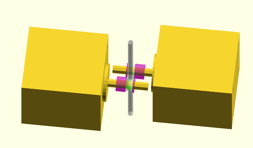
At the end of tonight's meeting I mentioned my dual-motor extruder idea.
My question to you nice folks was around the quick comment that Frank and Bill G. had in regards to whether the motors ought to be wired in series or in parallel. I was planning on wiring them in parallel, but would like to take this opportunity to learn something new if possible.
Attached is a sketch of the likely terrible idea that I'm going to try.
Thank you,
Elliot

Bill Seiler
May 21, 2015, 2:03:02 AM5/21/15
to bay-are...@googlegroups.com
I hope this is a bowden. Thats alot of weight.
--
You received this message because you are subscribed to the Google Groups "Bay Area RepRap" group.
To unsubscribe from this group and stop receiving emails from it, send an email to bay-area-repr...@googlegroups.com.
To post to this group, send email to bay-are...@googlegroups.com.
Visit this group at http://groups.google.com/group/bay-area-reprap.
For more options, visit https://groups.google.com/d/optout.
Elliot
May 21, 2015, 2:04:56 AM5/21/15
to bay-are...@googlegroups.com
Yes, it would be for bowden. The idea would be to drive both sides of the filament and have an increase in filament driving power.
For 1.75mm filament, nema14 motors would be a possible choice.

wolfmanjm
May 21, 2015, 2:05:14 AM5/21/15
to bay-are...@googlegroups.com
Is this to increase torque? If so why not just use a gearhead or a bigger stepper motor?
Elliot
May 21, 2015, 2:07:17 AM5/21/15
to bay-are...@googlegroups.com
Two nema17s are cheaper than one geared stepper (which I have two of) and it would drive both sides of the filament.
Also, the geared steppers that I've seen have 8mm output shafts, which means a larger diameter drive pulley, which means a loss much of the advantage of a geared stepper.
Elliot
--

danman
May 21, 2015, 12:36:34 PM5/21/15
to bay-are...@googlegroups.com
I don't have alot of experience with 3mm filament, is it common for a nema 17 to have insufficient torque for a direct drive config?
If there is a clogging problem that consistently occurs after X minutes of extruding, that is usually caused by heat creeping up the barrel. If that is the problem, fixing heat problems in the extruder might be an easier solution.
When the clogging occurs, does the stepper cut into the filament or does it start skipping steps? If skipping steps is happening, more motors seems the way to go. If cutting into the filament is happening, then torque is sufficient, maybe friction could be increased instead (better drive gear, more pressure, etc.)
-Dan

Derrick Schneider
May 21, 2015, 12:45:28 PM5/21/15
to bay-are...@googlegroups.com
I can't answer the more technical parts of the question, but to answer the first part of this: The Makerfarm Prusas use a Nema 17 and Greg's extruder (direct-drive) even for 3mm filament.
--
Writer. Programmer. Puzzle Designer.
http://www.obsessionwithfood.com
http://www.obsessionwithfood.com
Elliot
May 21, 2015, 1:27:23 PM5/21/15
to bay-are...@googlegroups.com
Dan,
Nema17 is enough for a direct-drive non-bowden extruder (which is what I have on my printer) but it cannot print at "high" speeds, and Ken had troubles using it with a bowden setup. My terrible two-motor idea should hopefully address those two problems.
It's not a clogging problem; it's a problem that when you start extruding above at a high-ish speed I can't remember what it was but something like 100mm/min the backpressure becomes more than what the motor can power through. Anything below 100mm/min is fine (for non-bowden.)
Elliot
On Thu, May 21, 2015 at 9:36 AM, danman <dte...@gmail.com> wrote:
Elliot
May 21, 2015, 1:29:16 PM5/21/15
to bay-are...@googlegroups.com, Frank Worrell, Willialm Green
Frank/Bill,
I'll specifically name the people who I'd like to ask!
Bill, you said that series would be better than parallel.. I was wondering if you had some pointers to more information around that.. I thought that if the motors/fans/whatever were wired in series, then one motor/fan/whatever might consume all of the "power" and the one further down would be starved?
Elliot

Jon Pannell
May 21, 2015, 2:11:23 PM5/21/15
to bay-are...@googlegroups.com
Elliot,
In most others situations wiring in series would do that but the stepper drivers we use are current limited, IE the chop up the voltage to maintain set current. If the motors are low enough resistance (for the supply voltage) you should not notice a difference. Wiring them in parallel would require doubling the current (and dissipate more heat in the driver).
You might be able to measure the voltage over the windings (or look at the datasheet) and see if you have enough remaining voltage.
Jon
Sent from my iPhone
Sent from my iPhone
Elliot
May 21, 2015, 3:18:32 PM5/21/15
to bay-are...@googlegroups.com
Jon,
Elliot
Thank you for the excellent response!
Elliot

Frank Worrell
May 22, 2015, 7:37:19 PM5/22/15
to Bill, Elliot, bay-are...@googlegroups.com
> In the systems I have seen, the driver voltage seems to be more
of a limitation than the current
I am quite sure that is not true for modern stepper motor drivers with low resistance stepper motors.
The current is the limit, not the voltage.
The drivers will try to drive the power supply voltage into the motor and either current limit or burn out.
For current drive, the "voltage" the driver provides is purely an illusion.
You can put almost any voltage across the motor inductance
as long as you control the pulse width to limit the current.
I say almost because as the voltage increases, eventually the pulse gets too narrow for fine control.
(If you increase voltage very high anyway, your insulation will break down.)
What is actual happening is that the H bridge driver is driving +12, -12, or 0 volts
PWM (Pulse Width Modulated) into an inductor to control the current.
Motors may actually be "exactly the same", but not in the way you think.
On motors of the same type from the same manufacturer,
I bet the number of turns of wire IS exactly the same, but the resistance of the wire can vary.
What you care about is the number of turns times the current, that is what makes the magnetic fields.
Most of our stepper motors are really low resistance, low resistance == current drive.
For current drive, you want the motors in series so the windings have the same current.
Some stepper motors do have higher resistance windings, for example 30 ohms.
Higher resistance == voltage drive.
For voltage drive, you want the motors in parallel so the windings have the same voltage.
For voltage drive, you want the motors in parallel so the windings have the same voltage.
I am not sure, but the high resistance stepper motors may be going out of style.
My guess is there are multiple disadvantages:
They take more turns of finer wire.
More turns probably costs more to manufacture.
Finer wire probably means the resistance varies more.
Voltage drive means the current depends on the resistance.
The motor resistance limits the current you can drive from a low voltage DC power supply.
Frank
On Thursday, May 21, 2015 7:11 PM, Bill <bilg...@pacbell.net> wrote:
Elliot, Frank, and everyone else,
I've given this some additional thought and I can see now how useing a single driver with two stepper motors in paralell would be better than in serial, AS LONG AS BOTH MOTOTRS ARE CLOSE TO EXACTLY THE SAME. Here is my take on why:
Stepper motors are really driven by the CURRENT going through the coils. Modern stepper drivers use a sort of regulated PWM to vary the current. If the motors are wired in SERIES, it is certain that the same current will go through the coils of both motors, BUT, the driver would need to output twice the voltage to send a given current through two motors as it would through one.
If two motors are wired in paralell then the voltage the driver needs to output is the same as for one motor, but the current doubles. Unfortunately, any differences in inductance, or resistance in the coils for the motors will cause the current flow to be unbalanced, and the motors to develope different amounts of torque.
In the systems I have seen , the driver voltage seems to be more of a limitation than the current, and I suspect that if you use the same brand and model for both motors the differences will be small enough to not matter, so it makes sense to wire them in paralell.
Please feel free to comment, and / or point out problems with this explination.

kongorilla
May 22, 2015, 9:53:12 PM5/22/15
to bay-are...@googlegroups.com, frank_...@yahoo.com, efo...@firetaco.com, bilg...@pacbell.net
Elliot, I'll let others more qualified than me discuss the merits of parallel vs. series, but I'm wondering if you've taken a look at the Bondtech extruder? While it does required a geared motor, it is a "double drive" (two counter rotating drive gears) extruder that promises to eliminate problems caused by back pressure. It's a CC-BY-NC-SA design, and the STLs are available, so you can take a close look at it. I don't know how it performs at high speed.
Printrbot was working along similar (double drive) lines last year, without the geared stepper. IIRC, some people who tried early releases of the Printrbot version had trouble because it was unforgiving of filament width issues. I've only heard acclaim for the Bondtech. Trying Printrbot's version is considerably cheaper (though it never left beta and it's no longer in stock).
Maybe a counter-rotating drive gear design is something to consider, rather than adding another motor?
Elliot
May 22, 2015, 11:48:03 PM5/22/15
to bay-are...@googlegroups.com, Frank Worrell, Willialm Green
Steve,
Yes, the Bondtech extruder looks very very nice! I actually mentioned it on the list within the last few weeks and Walter was enough to bring his to B2 the last time we were there. It is one impressive looking piece of engineering. It is also, however, >$100 just for the machined parts, or $180 for the full extruder (plus shipping and handling for both.) The stepper is also a fairly expensive piece of kit.
The printerbot version is a lot cheaper, but is a no-go for me while I'm still using 3mm filament. For that matter, I don't think the 3mm bondtech could be adapted to be used with 1.75mm filament (since the gears need to mesh.)
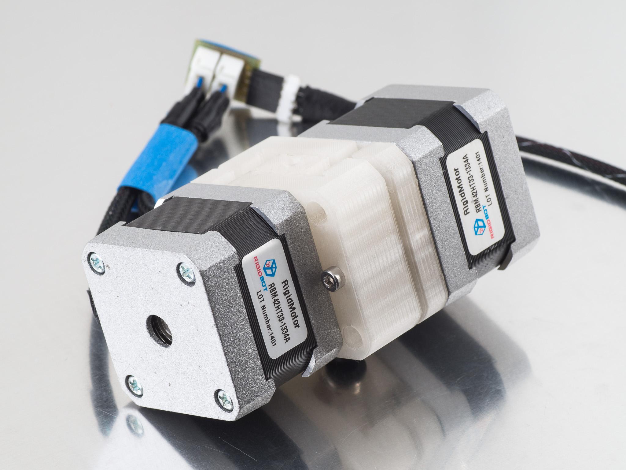
So, I started with the counter rotating idea, and am attempting to make it cheaper and have a bit more oomph. The design is parametric and uses "standard" off-the-shelf components like Mk7 / Mk8 hobbed bits (~$5*2) and standard NEMA14 or NEMA17 motors (~$15*2).
Thank you for the suggestion, and I may very well spend the extra money once I watch this experiment fail. :)
Elliot
kongorilla
May 23, 2015, 4:00:12 AM5/23/15
to bay-are...@googlegroups.com, frank_...@yahoo.com, bilg...@pacbell.net
Oh yes, I see that message now, sorry. I'm slowly catching up with my google group messages after weeks of taking care of my pneumonia-stricken family. It's been a rough, cough-filled May at my house.
Before I had a printer, during the era of the MB Cupcake (a printer I wasn't willing to pay for), I modeled a laser cut extruder design that included counter rotating gears (standard metal gears) to engage the filament. Most of my printer designs from that era were embarrassingly naive, but that extruder might have worked had I ever made it. I ended up buying the much more simple Makergear extruder which worked fine (and still does), so my complicated design is buried on a backup disk, awaiting rediscovery.
(Has it only been five years since the Cupcake? It seems like ancient times -- so much development has happened since. I came close to winning a Cupcake. I suppose I was better off losing).

Brandon Heller
May 27, 2015, 2:42:40 AM5/27/15
to bay-are...@googlegroups.com, bilg...@pacbell.net, frank_...@yahoo.com
Let us know how it works for you.
I think it'll work just fine. Unlike the bondtech (or any setup with meshed gears), the Fostruder (yes, I just named your design) could potentially be adjusted to varying filament diameter without causing a change in backlash or requiring parts changes. That seems like a good quality. The only issue I can think of, aside from double cost, is that you're increasing the pressure on the bowden fittings; if these are push-fits, they may fail faster.

jorwex
May 27, 2015, 3:43:47 PM5/27/15
to bay-are...@googlegroups.com, bilg...@pacbell.net, frank_...@yahoo.com
...Fostruder, not to be confused with fRostruder...

Walter Hsiao
May 27, 2015, 4:17:41 PM5/27/15
to bay-are...@googlegroups.com
SMW3D has the 1.75mm version of the BondTech for $145 + shipping (3mm out of stock) - http://www.smw3d.com/bondtech-v2/. With bondtech.se, part of the price is VAT, so it may end up cheaper than $180 to ship to the US. I'd rather see results of the dual motor extruder though.
Elliot
May 29, 2015, 2:33:39 AM5/29/15
to bay-are...@googlegroups.com
Well... it's up if anyone is interested: https://github.com/elliotf/two-motor-extruder
I chickened out on the Fostruder extruder name. Maybe if it prints well I'll use that. :)
I'll let you know if/how it prints once I design a bowden X-carriage for my Graber.
Elliot
On Fri, May 22, 2015 at 10:41 PM, Walter Hsiao <whs...@gmail.com> wrote:
SMW3D has the 1.75mm version of the BondTech for $145 + shipping (3mm out of stock) - http://www.smw3d.com/bondtech-v2/. With bondtech.se, part of the price is VAT, so it may end up cheaper than $180 to ship to the US. I'd rather see results of the dual motor extruder though.
--

Ken Snyder
May 29, 2015, 2:58:36 AM5/29/15
to bay-are...@googlegroups.com
Got my BondTech extruder today and tried it out. It is amazing. It was a bit scratched and banged up right out of the box, but the performance is very impressive. I've been having trouble with my E3d V6 hotend that has a tendency to jam/clog which leads to the extruder grinding through the filament and/or misstepping.
With the BondTech V2 1.75mm bowden the grinding and misstepping is a thing of the past. The extruder is so strong that it forces the filament into the bowden tube until the tube is forced out of the push fit connector. The BondTech extruder lives up to its claims.
Time to fix the problem with the hotend now....
Brandon Heller
Jun 7, 2015, 3:10:49 AM6/7/15
to bay-are...@googlegroups.com
Was curious and took a look. Unsolicited feedback/questions:
- how does this mount to your printer(s)?
- support's needed for the main part, so that the overhangs by where the NEMA17 face would touch are supported, right? Just checking here - seems like you're using the 45 degree rule but ran out of space.
- the hinge m5 aligns with the path of the filament, so the hole nearby is for the filament/pushfit to come out at a little bit of an angle, right? The hinge should not be under significant stress because you have big interior faces of the two halves next to each other. I would try to ditch the M5 and use the same size M3 as for the motor mounts, to reduce one part and screwdriver needed. If you slightly increase the height of the main (thicker) of the two halves, and decrease the other an equal amount, I think you can have enough beef there to put a nut trap where the hinge m5 goes now and place it so the nut trap doesn't intrudes into the filament's path. Then you can have a straight filament entrance. You might be able to also reduce the height a bit as well. Just a thought.
Why do I care here? Because I've always been annoyed at the need to recalibrate for each type of filament after a change. Even with perfect 1.75mm OD, different filaments have a varying amount of "squish" from the same roller pressure, and those few percentage points do affect calibration. If you have an extruder that grabs from both sides, then in theory its steps/mm should not depend on how far the roller pushes the filament into the drive gear (changing the effective diameter). This advantage would be shared w/the printrbot and bondtech designs.
Elliot
Jul 24, 2015, 1:00:58 AM7/24/15
to bay-are...@googlegroups.com
Mild resurrection.
Elliot
I'm doing test extrusions with the dual NEMA17s but am getting disappointing results.
Unfortunately, I'm using an E3D V6, which I've not used before. It seems like its nozzle pressure is a lot higher than the J-head (what I normally use) -- or is that all in my head?
Basically, I can't seem to throw enough current at the problem; the motors are ice cold but the smoothie drivers are boiling hot (driving 1.5A through the pair of extruders.)
It seems that the smoothieboard's 4988 drivers top out at 2A .. would I have any better luck with an Azteeg X5 (which has 8825's) ?
Ideas welcome!
Elliot
Ken Snyder
Jul 24, 2015, 2:30:00 AM7/24/15
to bay-are...@googlegroups.com
Elliot,
I'm not surprised you're having trouble since you're using the E3D V6. You are right that the nozzle pressure is much higher compared to the J-head. After pushing a couple of spools through my E3D V6, the pressure went up on mine too. I kept having to increase the temperature and cut the speed. The all metal hotend needs to be remmed or cleaned out after every spool of printing. Compared to the old J-heads, the E3D V6 is an unreliable, low performance, high maintenance nightmare! My advice is to use the J-head instead while you're prototyping your extruder. Eliminate all the problems with the E3D V6 from the equation. Go with what you know works.
From now on, I will only use an all metal hotend when I need one. Interestingly, Filastruder's new hotend, the E3D Lite-6, puts the PTFE tube through the heatsink to the nozzle, like the J-head. But since the brass nozzle is so short compared to the J-head, it's speed is still limited. The J-head is still a superior design over this new one.
Now about the extruder design. It's a noble effort, one I think will work with the J-head, but I think the BondTech V2 dual geared hobbed pulleys is a better approach. I really like my V2, but the price is ridiculous at $180+. You can get the 5:1 gear reduced NEMA 17 for about $30 off AliExpress. I'm sure somebody's going to sell the geared pulleys very soon if they are not already. If anybody finds them, please let me know!!!!! The STLs for the housing were released, so I think the extruder could actually be made for around $40-45. The only weak point on the extruder is the bowden adapter. I made a groove mount bowden adapter out of aluminum on my lathe and tapped it so that I could use the spring loaded brass push-fit connectors. It's a nice little upgrade.
You can do this upgrade to the $10 Chinese E3D V6 knock-offs too. I also drilled the inside about 5mm deep and 3mm diameter to seat a 3mm OD 2mm ID PTFE tube and run it through the heat-break to the nozzle. It makes for a much more reliable hotend than the real E3D V6, although you're limited to about 250C.
What I would like to see, is your take on the BondTech V2 housing. Maybe you could come up with something that doesn't require the brass inserts.
Ken
Bill Seiler
Jul 24, 2015, 5:30:11 PM7/24/15
to bay-are...@googlegroups.com
I have had the same problem with my E3D V6 clone. The back pressure got so bad it just stopped working.
I built a hotend / bowden / extruder as Ellioit suggested a few meetings back. Now my bowden tube extends from the extruder all the way down to the brass nozzle.
The back pressure went way down. I had to reduce my extruder steps/mm by half too.
I am using a china clone 3mm hotend. I removed the 3mm nozzle and replaced it with a 1.75mm nozzle. I am using 3mm OD 2mm ID PTFE tubing for my bowden tube.
I thread 3mm nut onto the PTFE tubing to clamp it at the hotend. I tapped a quick release fitting to 3mm and I thread it onto the extruder end.
Elliot
Jul 24, 2015, 9:17:45 PM7/24/15
to bay-are...@googlegroups.com
I think my problem is just one of "not enough power" so I think I might just redesign my extruder to use the geared steppers..
Walter Hsiao
Oct 22, 2015, 10:56:33 PM10/22/15
to Bay Area RepRap
Just can't resist terrible ideas :) Here's a version that seems to work, at least for 1.75mm filament. I used 2 E3D Hobgoblin drive gears and the motors are hooked up in series using Peter Stoneham's connector board. It uses heat press brass inserts from McMaster Carr and two M3 screws adjust the tension on the gears. The outlet is designed for a 1/8" threaded pushfit connector.
I've only printed a couple of things with the extruder just to try it out, I don't actually have any use for it right now.
Bill Seiler
Oct 23, 2015, 1:01:10 PM10/23/15
to bay-are...@googlegroups.com
Thanks for stl. I am printing int now.
I am printing with the filament input side down.
Cura says it will take 4 hours!
On Thu, Oct 22, 2015 at 7:56 PM, Walter Hsiao <whs...@gmail.com> wrote:
Just can't resist terrible ideas :) Here's a version that seems to work, at least for 1.75mm filament. I used 2 E3D Hobgoblin drive gears and the motors are hooked up in series using Peter Stoneham's connector board. It uses heat press brass inserts from McMaster Carr and two M3 screws adjust the tension on the gears. The outlet is designed for a 1/8" threaded pushfit connector.I've only printed a couple of things with the extruder just to try it out, I don't actually have any use for it right now.
--
Elliot
Oct 23, 2015, 1:43:21 PM10/23/15
to bay-are...@googlegroups.com
Thanks for the .stl and thanks for the pointer to https://oshpark.com/shared_projects/ziCh46Kn -- I just ordered three and plan on using them for my graber and extruder.
I also appreciate the totally different though about the mechanism for adjusting tension/tolerance -- a literal twist on it, rather than sliding.
Currently looking at how to print it.. the drop-down filament supports seem.. tricky? I'm assuming you used supports for that?
Bill, what settings are you using? My cura says 1hr40min with .3mm layer height, 1.5mm top/bottom, 2mm shells, .5mm extrusion width, 24% solid, 60mm/sec
Walter Hsiao
Oct 23, 2015, 4:35:51 PM10/23/15
to Bay Area RepRap
Yeah it should be turned upside down, I was too lazy to orient it properly, it's a bit more of a hassle in Onshape. I used support in the center.
I just switched to a plastic E3D threaded bowden coupler on my Bondtech, if that works out I'll probably switch this design over to use the same one (it's the same thread, just longer). I can probably make it printable without supports too, if I use a few diaphragms. I designed it for the motors I had on hand so it probably won't work for motors with longer shafts. With the hobgoblin drive gears the set screw should fall in the center of the hinge gaps and the set screws may need to be trimmed if they're too long.
Here's the design in Onshape if you want to modify it, the 3mm version is in a separate branch:
Bill Seiler
Oct 23, 2015, 7:47:01 PM10/23/15
to bay-are...@googlegroups.com
Well I printed it and assembled it. It sort of works. The Walter tight tolerances are killing me. My MK8 gear lock scews are sticking up too far and rubbing. I will play around with your cad and open it up a little. Maybe print a new part tonight.
Also tried the parallel and series motor connections. The series works better.
Walter Hsiao
Oct 24, 2015, 12:13:40 AM10/24/15
to Bay Area RepRap
Which MK8 gears are you using? I thought the cuts on the MK8 gears were too deep for two of them to hold 1.75mm filament? I used the E3D hobgoblin gears since they have a more shallow cut, but they're about 4 times as expensive.
Reply all
Reply to author
Forward
0 new messages