Open source hardware circuit diagram for uKenbak-1
78 views
Skip to first unread message

Mike Corrigan
Aug 19, 2021, 9:51:04 AM8/19/21
to uKenbak-1
Can anyone tell me where I can find the circuit diagram for the uKenbak-1?
My uKenbak-1 worked perfectly for about 24 hours, but now the Store button has become intermittent. I'd like to find the problem, but I can't follow the circuit traces under the sockets. I would really like to see the circuit diagram.

famousd...@gmail.com
Aug 19, 2021, 10:32:38 AM8/19/21
to uKenbak-1
Try this: remove the Atmeg328p chip and bend pin 13 out so when you plug the chip back in, that pin is not in the socket.
When pin 13 is high it acts like the "mem lock" switch is on. Maybe something is making a momentary connection.
Mike Corrigan
Aug 23, 2021, 11:17:34 PM8/23/21
to uKenbak-1
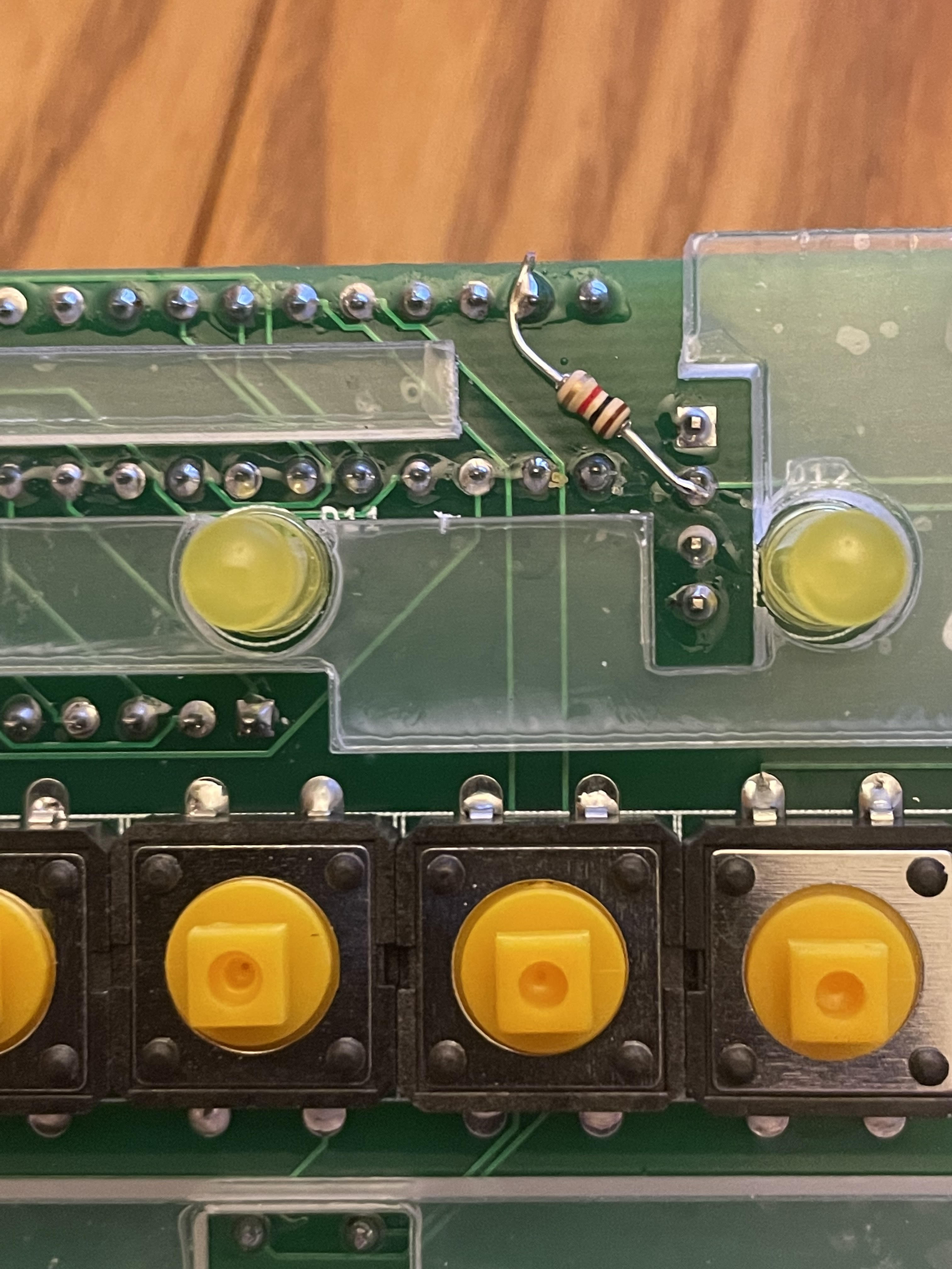
I continued to have intermittent problems with the Store switch. The problem was pin 13 as Chris suggested. Really the problem is that pin 13 is left floating (it is not connected to anything). High impedance CMOS inputs that are left floating can take on almost any voltage. This pin is read by the software, and because it is floating, it sometimes reads 0 and sometimes reads 1. When it reads as 1, the store switch is locked out. I fixed it by grounding the pin. Now it will always read as 0. In fact, as protection against the software ever making this pin an output and setting it to 5V, I grounded it through a 1K resistor. Now the store switch behaves perfectly. I also had to cut a little out of the acrylic spacer to give clearance for the resistor.

Vicente González
Aug 24, 2021, 4:35:31 AM8/24/21
to Mike Corrigan, uKenbak-1
Thanks, Mike.
I have just assembled the new uKENBAK-1, I have not observed this problem but I would like to understand it.I cannot find any reference to the use of pin 13 or the memory write lock function in the kenbakuino code. Could someone point to that part of the code?
regards,
Vincent
Vincent
--
You received this message because you are subscribed to the Google Groups "uKenbak-1" group.
To unsubscribe from this group and stop receiving emails from it, send an email to ukenbak-1+...@googlegroups.com.
To view this discussion on the web visit https://groups.google.com/d/msgid/ukenbak-1/2c81b269-8f84-4c9d-95ba-5e70844bd605n%40googlegroups.com.
famousd...@gmail.com
Aug 24, 2021, 8:24:10 AM8/24/21
to uKenbak-1
Thanks for finding that Mike!
Added to line 4 of Buttons.h:
// LOCK switch pin - CLD
#define PIN_LOCK 7
Added to line 18 of Buttons.cpp:
// lock switch - CLD
pinMode(PIN_LOCK, INPUT);
Added to line 190 of MCP.cpp:
//CLD - is lock switch set?
if(!digitalRead(PIN_LOCK))
Here is the relevant part of the schematic:

So if you don't want to add the resistor you can just upload the code from Mark Wilson's Github which would not have the mem lock code. This is only used in the full-size Kenbak-1 anyway.
famousd...@gmail.com
Aug 24, 2021, 8:29:45 AM8/24/21
to uKenbak-1
I was trying avoid having a stock of Atmega328 chips with two different versions of the code, but I guess I will have to do that and make sure the ↨µKenbak-1 kit is sent out with the "non-memlock" code.
Mike Corrigan
Aug 24, 2021, 10:40:26 AM8/24/21
to uKenbak-1
When I added the resistor (shown in a previous post), it fixed the Store problem but caused another. Since I connected the resistor directly to the ground of the USB to UART module, it bypassed the power switch (which connects the circuitry to the USB to UART ground). The Atmega328 did not see a high enough voltage to run (because of the resistor), but it was enough to power the other chips, causing any LEDs that were on, when the power switch was turned off, to remain lit. Chris suggested fixing this as in the partial circuit diagram he posted. (This from the full-size Kenbak-1). I changed the resistor to the 10K he recommended and connected it this way and now everything works correctly. Thanks Chris!
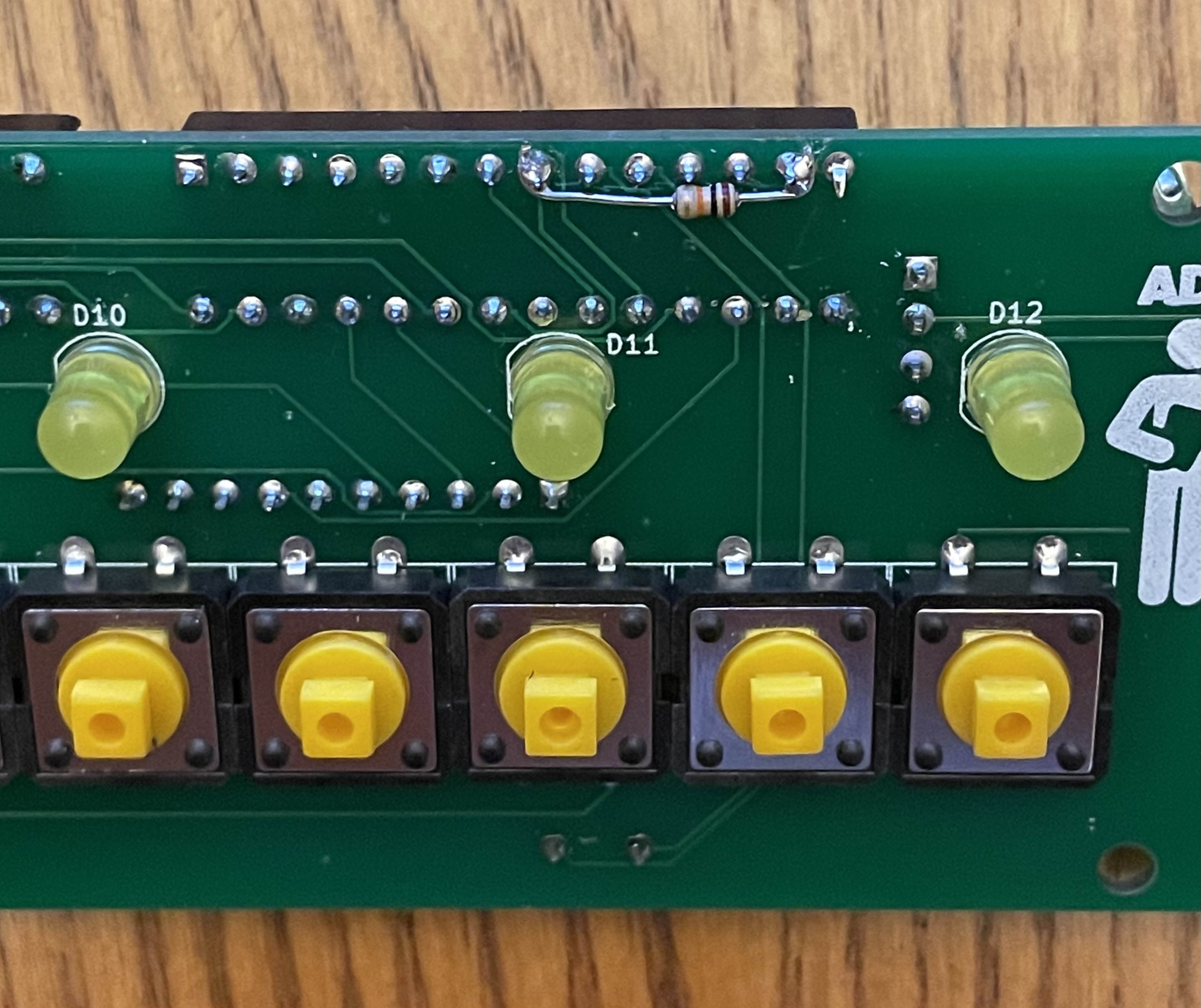
If I had done it this way originally I would not have needed to modify the acrylic spacer.
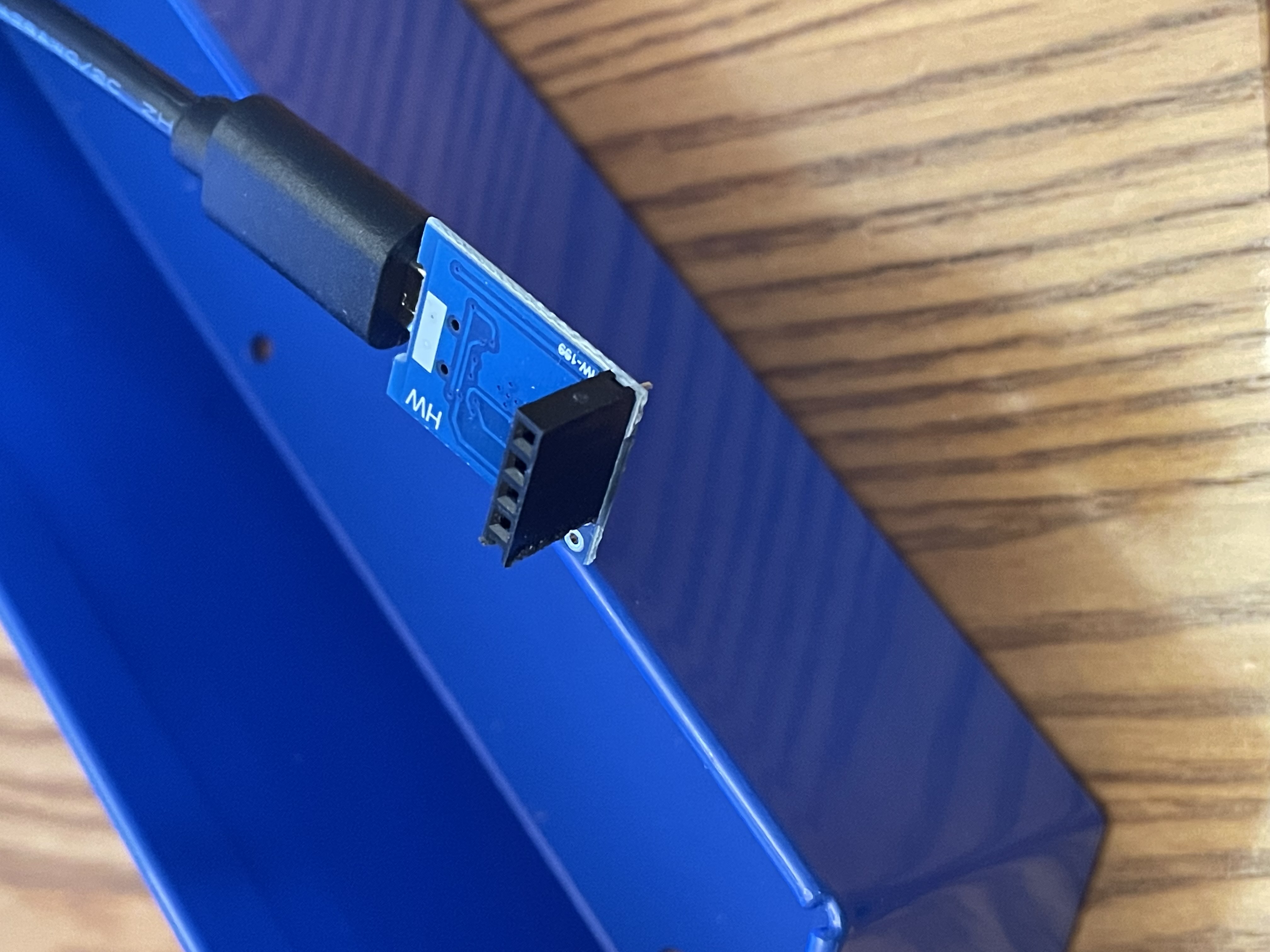
While taking everything apart and putting it back together several times, I managed to rip the micro USB connector from the USB to UART module :(
I found exact replacements at: https://www.amazon.com/NOYITO-CP2102-Converter-Downloader-Arduino/dp/B07D54K82D/
Two for $7.99
To avoid this problem going forward I soldered a female header to the module and then just plugged it into tall male header instead of soldering it.
Chris' software solution is the easiest fix, if you already have an Arduino Uno (which I do not)
New resistor solution:
Female header on USB to UART module

Mark Wilson
Aug 24, 2021, 2:26:12 PM8/24/21
to uKenbak-1
You could use
// lock switch - CLD
pinMode(PIN_LOCK, INPUT_PULLUP);
Mike Corrigan
Aug 24, 2021, 2:31:48 PM8/24/21
to uKenbak-1
I don't see how adding a pullup would help. The pin is active high...the memory is locked when the pin is high.
Mark Wilson
Aug 24, 2021, 2:36:18 PM8/24/21
to uKenbak-1
Oh I see, sorry. It is pulled down. Probably too early for me to be posting.
Reply all
Reply to author
Forward
0 new messages