Gosund SP112 vom Jahr 2021

Sergey N
ich bin neuer im Forum. Ich habe etwas über mein Problem mit den gerade gekauften SP112 recherchiert und leider gar nichts gefunden. Es könnte auch sein, dass ich etwas nicht merke/verstehe/begreife/falsch tu usw. Deswegen möchte ich einen Rat von der erfahrenen Herrschaft lesen oder eine Diskussion anstoßen.
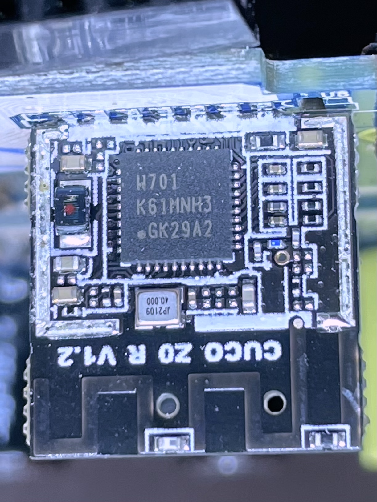
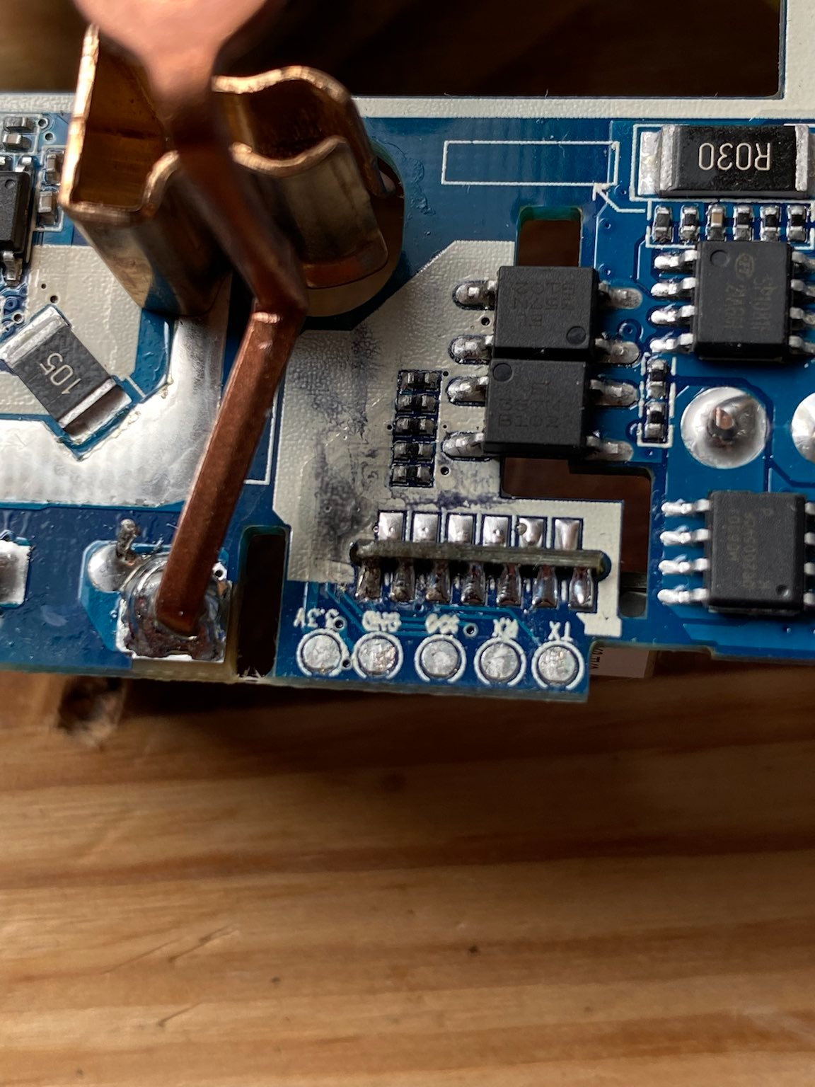
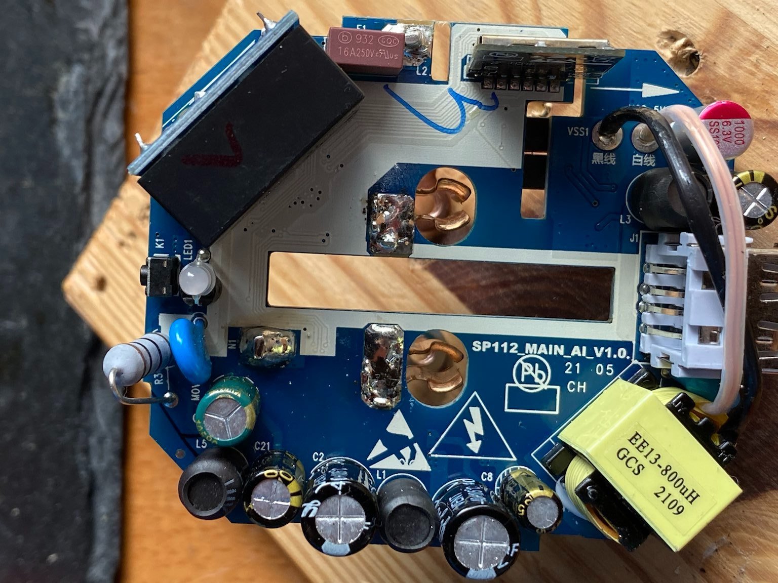
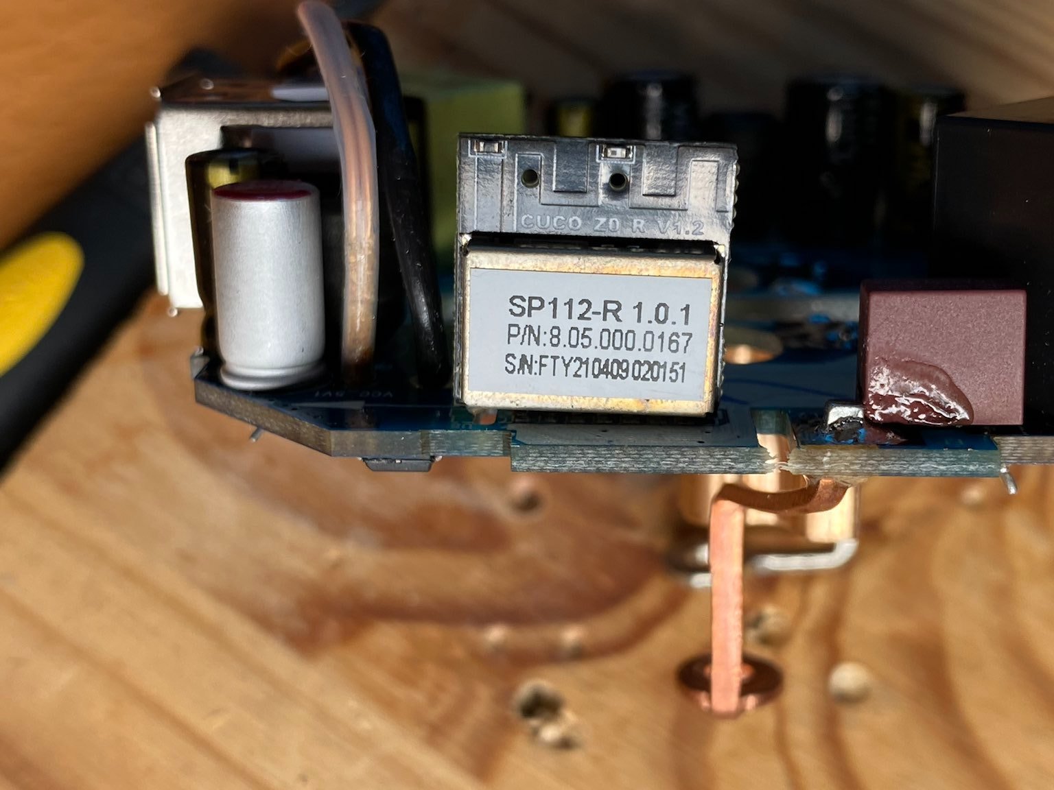
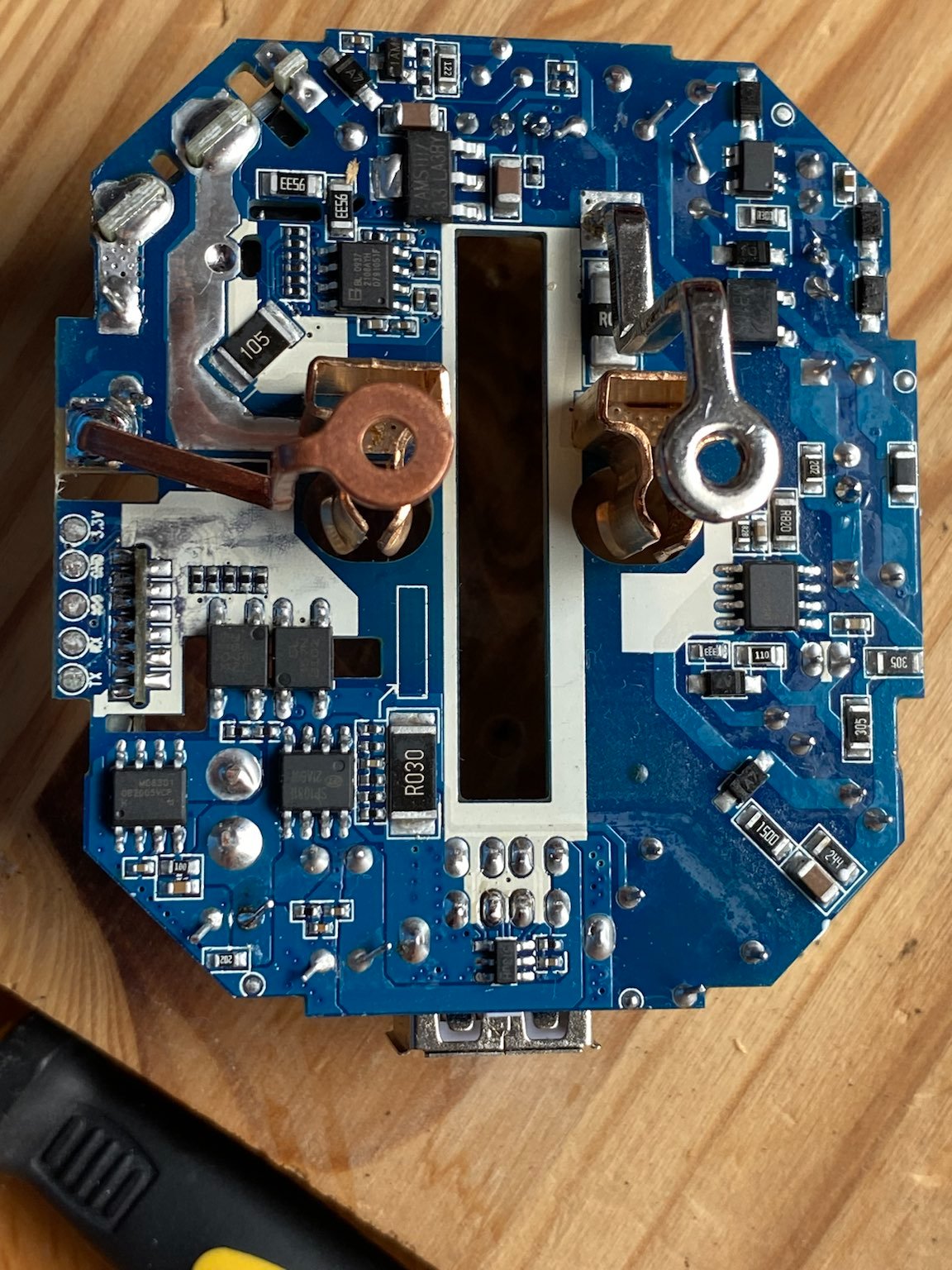
Die neuen SP112 vom Jahr 2021 mit zwei USB-ports sehen genau so, wie frühere Modele. Allerdings lassen sich mit Tasmota auf keiner Weise flashen. Über die Meldungen, dass die Methode tuya-convert über WLAN bei SP112 nicht mehr funktioniert, habe ich bereits gelesen. Aber die serielle Methode funktioniert leider bei mir auch nicht. Beschreibung: Alles angeschlossen, angelötet nach Referenz . Das erste, was auffällt, dass die Leuchte nach dem Auflösen der IO0-Brücke nicht lange Rot leuchtet, sondern nur 4 Sekunden. tasmotizer.py gestartet (probiert auf Macos/Linux), den richtigen SerialPort gewählt, release 9.5.0 tasmota.bin beim Image gesetzt. "Tasmotize!" geklickt und nach einer Weile "Failed to connect to ESP8266: Timed out waiting for packet header" angezeigt bekommen. Wenn man die Platine anschaut, fällt auf, dass sie etwas anders als die auf den Bildern von alten Youtube-Videos und der Anleitung von tasmota.info ist. Ich habe die Bilder hochgeladen. Hat jemand Erfahrungen mit dieser Version von SP112?
Wenn ich Recht habe, ist diese Version im Moment nicht flashbar mit den aktuellen Versionen der Flash-Programme. Das sollen Bastler wissen, finde ich.


Erix
--
You received this message because you are subscribed to the Google Groups "TasmotaUsers" group.
To unsubscribe from this group and stop receiving emails from it, send an email to sonoffusers...@googlegroups.com.
To view this discussion on the web, visit https://groups.google.com/d/msgid/sonoffusers/fc8fee09-3511-424f-994b-e260f1f1d657n%40googlegroups.com.
Sergey N

Philip Knowles
It may be worth connecting via a terminal programme when you power up as it will often give a clue to the firmware/device.
Regards
Phil K
Sent from Mail for Windows 10
From: Erix
Sent: 01 July 2021 09:02
To: TasmotaUsers
Cc: Sergey N
Subject: Re: Gosund SP112 vom Jahr 2021
Hi Sergey,
"Failed to connect to ESP8266": it's maybe not an ESP8266 or it's not in flashing mode.
do you have some serial debug outputs ?
did you try with esptool to "read" the chip ? which chip ID is it giving you ?
Erix
Le jeu. 1 juil. 2021 à 09:43, Sergey N <sergey.n...@gmail.com> a écrit :
Hallo allerseits,
ich bin neuer im Forum. Ich habe etwas über mein Problem mit den gerade gekauften SP112 recherchiert und leider gar nichts gefunden. Es könnte auch sein, dass ich etwas nicht merke/verstehe/begreife/falsch tu usw. Deswegen möchte ich einen Rat von der erfahrenen Herrschaft lesen oder eine Diskussion anstoßen.
Die neuen SP112 vom Jahr 2021 mit zwei USB-ports sehen genau so, wie frühere Modele. Allerdings lassen sich mit Tasmota auf keiner Weise flashen. Über die Meldungen, dass die Methode tuya-convert über WLAN bei SP112 nicht mehr funktioniert, habe ich bereits gelesen. Aber die serielle Methode funktioniert leider bei mir auch nicht. Beschreibung: Alles angeschlossen, angelötet nach Referenz . Das erste, was auffällt, dass die Leuchte nach dem Auflösen der IO0-Brücke nicht lange Rot leuchtet, sondern nur 4 Sekunden. tasmotizer.py gestartet (probiert auf Macos/Linux), den richtigen SerialPort gewählt, release 9.5.0 tasmota.bin beim Image gesetzt. "Tasmotize!" geklickt und nach einer Weile "Failed to connect to ESP8266: Timed out waiting for packet header" angezeigt bekommen. Wenn man die Platine anschaut, fällt auf, dass sie etwas anders als die auf den Bildern von alten Youtube-Videos und der Anleitung von tasmota.info ist. Ich habe die Bilder hochgeladen. Hat jemand Erfahrungen mit dieser Version von SP112?
Wenn ich Recht habe, ist diese Version im Moment nicht flashbar mit den aktuellen Versionen der Flash-Programme. Das sollen Bastler wissen, finde ich.


--
You received this message because you are subscribed to the Google Groups "TasmotaUsers" group.
To unsubscribe from this group and stop receiving emails from it, send an email to sonoffusers...@googlegroups.com.
To view this discussion on the web, visit https://groups.google.com/d/msgid/sonoffusers/fc8fee09-3511-424f-994b-e260f1f1d657n%40googlegroups.com.
--
You received this message because you are subscribed to the Google Groups "TasmotaUsers" group.
To unsubscribe from this group and stop receiving emails from it, send an email to sonoffusers...@googlegroups.com.
To view this discussion on the web, visit https://groups.google.com/d/msgid/sonoffusers/CANgsbDV9yKmaWA5-mh2sc1rG3Jwknth1yNy-uq5EbcGJY3MPaA%40mail.gmail.com.

Zaf
I have the same Problem with same new AI Board, and still have the board:)
Philip Knowles
This is what I get from an ESP32 (I’m using Tera Term on Windows). Up until 0.160 is the hardware after that is Tasmota.
If you are seeing nothing at all try to swap Rx and Tx
ets Jun 8 2016 00:22:57
rst:0x1 (POWERON_RESET),boot:0x13 (SPI_FAST_FLASH_BOOT)
configsip: 0, SPIWP:0xee
clk_drv:0x00,q_drv:0x00,d_drv:0x00,cs0_drv:0x00,hd_drv:0x00,wp_drv:0x00
mode:DOUT, clock div:2
load:0x3fff0018,len:4
load:0x3fff001c,len:1044
load:0x40078000,len:8896
load:0x40080400,len:5828
entry 0x400806ac
ÿ
00:00:00.002 HDW: ESP32-D0WD
00:00:00.054 UFS: FlashFS mounted with 48 kB free
00:00:00.138 CFG: Loaded from File, Count 14
00:00:00.152 QPC: Count 1
00:00:00.160 Project tasmota Tasmota Version 9.5.0(bluetooth)-1_0_6(2021-06-17T08:31:34)
00:00:00.161 iBeacon register for advert callbacks
00:00:00.162 M32: init: request callbacks
00:00:00.752 WIF: Connecting to AP1 pkm-24m Channel 2 BSSId C0:25:2F:01:EB:55 in mode 11n as ESP32-1...
00:00:05.618 WIF: Connected
13:49:00.232 HTP: Web server active on ESP32-1 with IP address 192.168.0.103
13:49:00.786 QPC: Reset
13:49:01.140 RSL: INFO1 = {"Info1":{"Module":"ESP32-DevKit","Version":"9.5.0(bluetooth)","FallbackTopic":"cmnd/DVES_DF5B88_fb/","GroupTopic":"cmnd/tasmotas/"}}
13:49:01.146 RSL: INFO2 = {"Info2":{"WebServerMode":"Admin","Hostname":"ESP32-1","IPAddress":"192.168.0.103"}}
13:49:01.156 RSL: INFO3 = {"Info3":{"RestartReason":"Vbat power on reset"}}
13:49:06.785 RSL: STATE = {"Time":"2021-07-03T13:49:06","Uptime":"0T00:00:14","UptimeSec":14,"Heap":149,"SleepMode":"Dynamic","Sleep":50,"LoadAvg":142,"MqttCount":0,"Wifi":{"AP":1,"SSId":"pkm-24m","BSSId":"C0:25:2F:01:EB:55","Channel":2,"Mode":"11n","RSSI":100,"Signal":-45,"LinkCount":1,"Downtime":"0T00:00:06"}}
13:49:06.807 RSL: SENSOR = {"Time":"2021-07-03T13:49:06","ESP32":{"Temperature":53.3},"TempUnit":"C"}
13:49:06.815 RSL: BLE = {"Time":"2021-07-03T13:49:06","BLEDevices":{"total":0}}
13:49:06.821 RSL: BLE = {"Time":"2021-07-03T13:49:06","BLE":{"scans":0,"adverts":0,"devices":0,"resets":0}
To view this discussion on the web, visit https://groups.google.com/d/msgid/sonoffusers/a48838d2-334c-43e3-a883-56d55498aab8n%40googlegroups.com.
Zaf

Michael Beyhs
Michael