Question PWM frequency
239 views
Skip to first unread message

Joachim Mueller
May 28, 2020, 5:21:53 AM5/28/20
to Smart Stepper
I have a question about the motor PWM frequency.
I measured around 100KHz PWM. Why is this so high?
The chinese clones use around 26 KHz.
Many motor driving chips (A4988, DRV8825) use 30KHz.
My thought was that a frequency higher than 25-30KHz just creates higher switching loss at the driver stage and heats up the motor because loss in the iron parts will rise without increasing motor performance.
Also more EM-noise problems expected with higher frequency.
Normally the frequency is set as low as possible and as high as necessary (out of the audible range).
Is there any specific reason why this controller uses a frequency 3 - 4x higher?
Joachim

Trampas Stern
May 28, 2020, 7:25:06 AM5/28/20
to Joachim Mueller, Smart Stepper
The smart stepper uses several different PWM signals. One is for the current limit for each phase, one is PWM for global A4954 current limit, and then there is the A4954 current limit system.


Higher PWM can increase the switching losses in a motor driver. Specifically these losses are when a transistor is not fully on and not fully off, ie in the linear phase. In the linear phase they act like resistors and as such consume power and get hot.
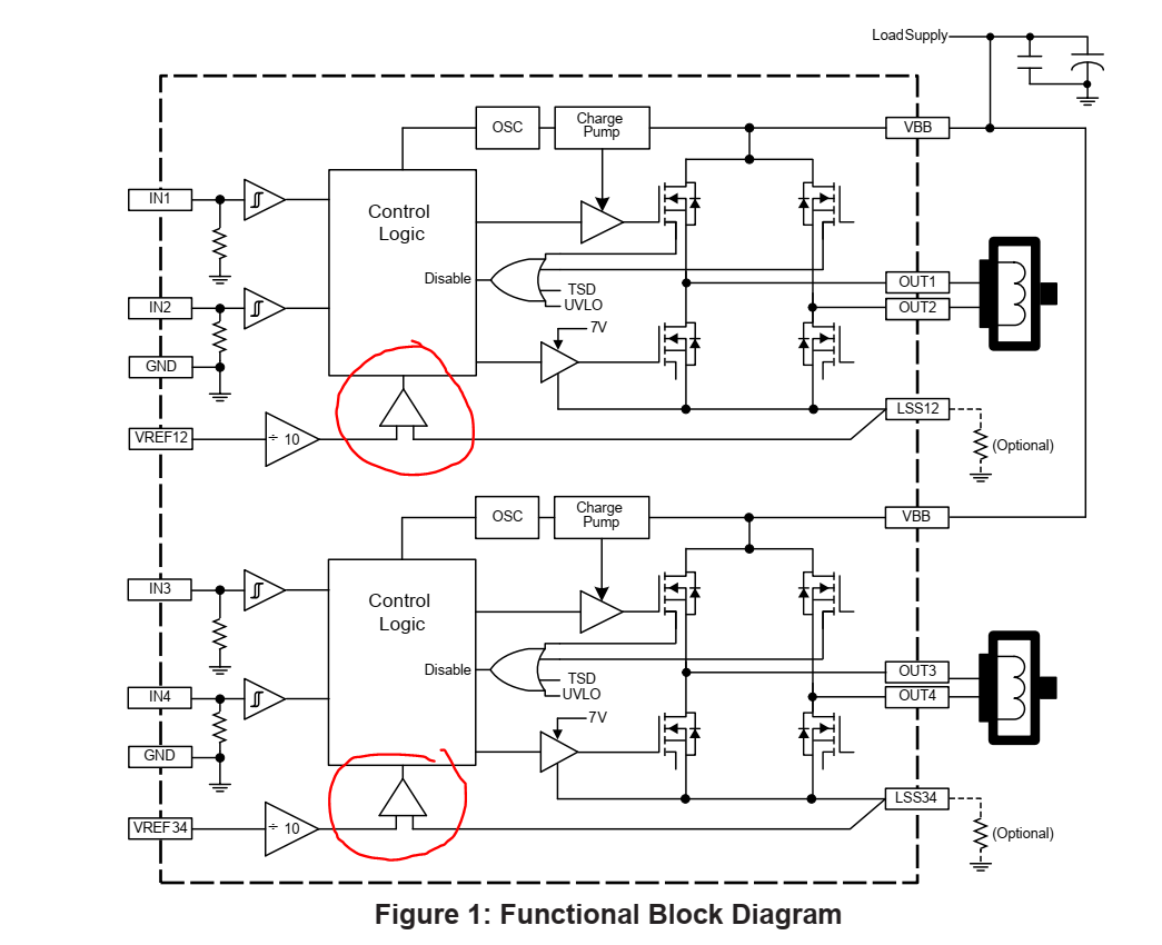
As background it is best to understand how the motor drivers work, I am sure several already know this but others on the list might not. The motor driver internally has a comparator which compares the analog voltage the micro provides via a PWM to the motor winding current. see image below.
The motor driver will turn on the motor coil and the current starts ramping up and then when the current through the sense resistor matches the input voltage, the motor driver will turn off. Since the motor windings are a coil (inductive load mainly) the inductor will try to hold the same current for some period of time. This time period is based on the motor you are using, bigger motor means more inductance means long time period. Note that when the A4954 first turns on the it ignores the current sense circuit for some time period, which is known as the blanking time. Which is 2-4us for the A4954. So for example if you have a small motor and large drive voltage it is quite possible that you exceed your motor current limit during the blanking time. However the A4954 does another trick to help with this when the current limit is triggered it will actually turn on power to the coil backwards for some time period, then after that short the coil leads together to allow the inductor to maintain the same current. This reverse then short behavior is called a mixed decay mode operation. Where fast decay is the reverse current, and the slow decay is the coil shorted.
The A4954 also has another trick where the user can PWM the IN1-IN4 pins to reduce the current. That is you can set the analog voltage for the current limit and/or also PWM the digital driver signals to limit current.
In the smart stepper firmware the PWM of the digital drive signals is possible as well as the analog voltage control.
Hence we have lots of methods to control the current to the motor, so how should we use them?
The answer here gets a bit complicated. First off if you do any PWM control of the motor you want to do it a fast rate, well above 20kHz. That is the human hearing is normally between 200Hz and 20kHz, so if you PWM in that range the motor turns into a speaker and you get buzzing noise. Note dog's can hear up to 45kHz so at 26kHz you might not hear it but your dog might. So the switching frequency is trade off not just between audio noise and power consumption but also with motion noise. That is the vibrations from the switching can also get into the motor position, especially for small motors and light loads on the motor.
A primary goal of the smart stepper boards was low noise, hence the PWM frequencies were picked to be very high. Also the boards and firmware were designed to work with wide variety of motors out of the box. However there are a lot of performance tweaking in firmware you can do to make it work better for your motor and application. For example the default firmware uses a PWM on the digital lines at 99% as it was found that this reduced noise and error on the motor position, however you can turn disable this in firmware and might help your application, see stepper_controller.cpp line 1459.
As far as power goes, the smart steppers drop the current when the motor is in the correct position, hence the power loss of the PWM is minimal so it really does not cause a problem. That is there is very little switching losses from the PWM in most applications, 3D printers for example.
Trampas
--
You received this message because you are subscribed to the Google Groups "Smart Stepper" group.
To unsubscribe from this group and stop receiving emails from it, send an email to smart-steppe...@googlegroups.com.
To view this discussion on the web visit https://groups.google.com/d/msgid/smart-stepper/ebade0af-3b66-4436-8d6d-e2110ab68b22%40googlegroups.com.
Reply all
Reply to author
Forward
0 new messages