Rev 4.0 CPU - it's alive!

Glenn Roberts
Having received the last of my recently ordered components today I decided to push through and complete the assembly of my Rev. 4.0 Z80 CPU board. achieved success at 10PM EDT!
This was quite a build. If this were a Lego set it would have been the Death Star! But with care and lots of double and triple checking I was able to get the CPU board to work right the very first time I turned it on! Amazing. Lots of new functionality built into the new ROM. Plenty to explore and get familiar with. Thanks to all the SEBHCers who made this new board happen. Great work!
Pics:
Board in machine: https://photos.app.goo.gl/J8u8dSBNsgcJvRUA7
Monitor on H19 screen: https://photos.app.goo.gl/JUuZ7BKwBKz15ajK9
- Glenn

norberto.collado koyado.com
Sent: Wednesday, June 9, 2021 7:30 PM
To: se...@googlegroups.com <se...@googlegroups.com>
Subject: [sebhc] Rev 4.0 CPU - it's alive!
You received this message because you are subscribed to the Google Groups "SEBHC" group.
To unsubscribe from this group and stop receiving emails from it, send an email to sebhc+un...@googlegroups.com.
To view this discussion on the web visit https://groups.google.com/d/msgid/sebhc/0e6a01d75da0%24a401a240%24ec04e6c0%24%40gmail.com.
Glenn Roberts
Here is the completed board:
https://photos.app.goo.gl/2zHGdyJ3UTFYscKTA
as shown this is jumper-configured for single board use (no H37).
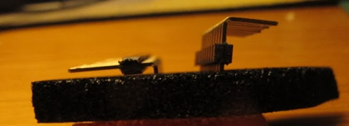
I’ve used the Pololu buck converters so this is capable of operation with a PC/ATX style power supply (which will require installation of the “12V” jumpers to bypass the 78/79L12 regulators.) I’ve installed headers in all jumper locations though the jumpers that short out the 8V to 5V line would never be needed with the Pololus. I’ve used a non-rechargeable lithium cell (and not installed the “charge” jumper. I find these last a long time (1 yr. +). I’ve not yet installed the right-angle header for the second serial port. I ran out of the part ☹. I have some lower profile headers but they leave very little clearance with the board. You can still use them with Molex female connectors but they will only go in one way so you need to be careful in making up the cable. I believe the higher profile one is the one indicated in the BOM (Jameco 1946041) so I’ll add some to my next order. the picture below shows the low profile (left) and high profile (right, preferred) angled headers:
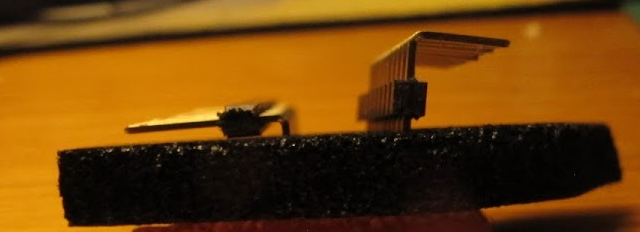
I’ve used a low profile (no flange) heat sink bracket from the manufacturing run that we did some years back (sorry, I don’t think there are any more of these out there?) I have not yet glued in a keyway between the Samtec edge connectors but will (highly recommended to avoid accidental power supply short.
I have installed the 3.68Mhz oscillator to allow possible high speed serial usage but left it jumpered for the 1.8 one, which is more than enough for my current needs.
The one glitch I encountered in building the board was the need to scrape off solder mask from the two LED positions before soldering (we had this same problem with the 8080 64K board? wonder why?)
I used the TL866II programmer to program the EEPROM and GALs using the images on Norberto’s web site
http://koyado.com/Heathkit/H8-Z80-64K-RTC-ORG0-V4.html
I purchased it on Amazon
https://www.amazon.com/gp/product/B01MA497YA
this is made in China and it took some careful navigation of their web site to find the English directions and avoid downloading “junkware” when installing the software, but once it was set up burning the devices was no problem.
I will now reconfigure the board for use with the H37 and attempt to boot HDOS. I will be building out the companion MMU V4 board and then experimenting with CP/M 3 (“Plus”).
Will post with any interesting issues or findings. As others build out their boards it would be useful to post any pertinent experiences or questions to this group. Good luck!
- Glenn
To view this discussion on the web visit https://groups.google.com/d/msgid/sebhc/SN6PR01MB38557FFDE9E217F8832B6413F7359%40SN6PR01MB3855.prod.exchangelabs.com.

Steven Feinsmith
To: se...@googlegroups.com <se...@googlegroups.com>
Subject: RE: [sebhc] Rev 4.0 CPU - it's alive!

Douglas Miller
Note, the V4 CPU board uses flash-memory parts, NOT legacy
EPROM/PROM. Linux support for the TL866ii is actually quite good,
by-passes the need to learn Mandarin, and the development team is
quite responsive and knowledgeable.
From a political activist point of view, it would be nice to
reduce the world's dependency on Chinese technology. But there are
still practical matters to overcome. Caveat Emptor.
To view this discussion on the web visit https://groups.google.com/d/msgid/sebhc/BL0PR03MB406739264198C079E251755DAC359%40BL0PR03MB4067.namprd03.prod.outlook.com.

David Troendle
Glenn Roberts
The TL866II was specifically recommended by several users on this list whose opinion I respect. the GQ looks very nice. tx.
For legacy UV EPROMS I still have my good old Heathkit programmer! 😊
To view this discussion on the web visit https://groups.google.com/d/msgid/sebhc/b04cd420-388c-4dc5-ad10-37a21abc8abbn%40googlegroups.com.

Dave McGuire
> I did find that even though the specs clearly stated the UV lights
> would not produce ozone, there was the distinctive chlorine-like smell
> of ozone when I open the box after erasing. So, you will need to take
> proper venting precautions and take care to shield from any UV that may
> leak out.
UV light. It is impossible to make a device that creates UV light that
does not create ozone in its surroundings, unless of course there's no
oxygen in its surroundings. So if some company claims "does not create
ozone!", they're lying.
-Dave
--
Dave McGuire, AK4HZ
New Kensington, PA
Steven Feinsmith
--
You received this message because you are subscribed to the Google Groups "SEBHC" group.
To unsubscribe from this group and stop receiving emails from it, send an email to sebhc+un...@googlegroups.com.
To view this discussion on the web visit https://groups.google.com/d/msgid/sebhc/a76c453a-2bdd-e498-370e-709a044fb5b9%40neurotica.com.
David Troendle
David Troendle

rand...@hotmail.com
Dave McGuire
> That is an odd incident. I have a 40 plus years old UV eraser made of
> metal with a built-in timer. The lamp is certified as UV-C exposure is
> harmful to human eyes (including animals). There is an interlock
> mechanism to lock the drawer when it turns on. It has a seal to prevent
> UV-C escape. I never smell any odor from this device. Perhaps your
> device uses cheap plastic that can react with UV exposure and may
> produce poison gas.
between ozone and deteriorating plastic. *All* UV light of wavelengths
less than about 250nm, regardless of the skin color of the manufacturer
of the light source, photolyzes oxygen into ozone.
It's a bit more complex than that, but them's the facts, as they
related to this issue.
If your device doesn't produce ozone, it's not producing shortwave UV
light.
> Also, if your device is from China, then it is
> dangerous and not UL-approved for safety.
nor does the lack of UL approval. And country of origin also has no
bearing on whether or not something is UL-approved.
However, the buyer should always beware, and with our society
consisting of well-trained consumers now, buyers are almost never wary.
And have you noticed how much utter garbage is "made in USA" now?
It's better to actually LEARN about a product and determine if it's
garbage or not, on a product-by-product basis, regardless of country of
origin. A lot of garbage comes out of China, but that country is quite
capable of producing good stuff, I've seen it with my own very
hard-to-please eyes. Pay attention and think.
And further, speaking of UL approval (wearing my "commercial product
designer" hat), the world is moving away from UL in droves. It's suitly
blood money, and everyone knows it. ETL certification is where everyone
is going instead. So, don't base your purchasing decisions solely on
the presence of a UL sticker.
> It is better to buy the best
> quality UV eraser device. Unfortunately, it is becoming more and more
> difficult to find it from eBay unless you pay $$$.
don't care about quality. Disgusting.
But UV light sources aren't exactly rocket science, and a cheapie will
get the job done, as long as the wavelength is where you need it to be.
In the context of cheap hobbyist-grade-at-best device programmers,
from any country, I've realized that I'm not going to live forever, and
as such, my time is valuable. I use a Data I/O UniSite. It was
Expensive with a capital 'E'. I can justify the cost because I do this
sort of work for a living, but even if that weren't the case, there are
far better uses for my time than fighting with cheap device programmers
and wondering if they got the programming algorithms right, so I'd still
have a UniSite. The result is that I never, EVER have issues
programming devices, and people send me weird components to program all
the time. Gotta program something? Just walk into the other room and
do it, with no concerns whatsoever.
So at least we agree on something, no TL866s or Willems for me,
thanks...my time is valuable.
norberto...@koyado.com
I’ve used a low profile (no flange) heat sink bracket from the manufacturing run that we did some years back (sorry, I don’t think there are any more of these out there?)
I have them if anyone interested and not sure how many are left.
Thanks,
Norberto
To view this discussion on the web visit https://groups.google.com/d/msgid/sebhc/0edf01d75deb%2463135cb0%24293a1610%24%40gmail.com.

norberto.collado koyado.com
Sent: Thursday, June 10, 2021 2:27 PM
To: SEBHC <se...@googlegroups.com>
Gery Kissel

norberto.collado koyado.com
glenn.f...@gmail.com
I have completed the Rev. 4 MMU and it passes the 512K test when I run it from the flash drive.
I changed my CPU from its initial configuration as follows:
- I moved JP8 to the right since instructions say that’s required for CP/M3
- I changed jumpers 15 and 18 to indicate external RAM and to disable on board RAM.
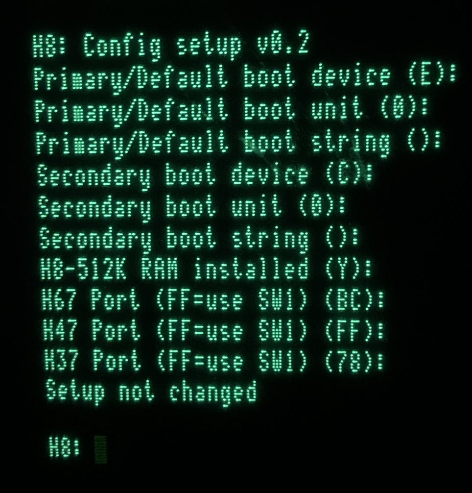
I also configured the EEPROM settings to correspond to my configuration (e.g. ‘36/67 port addresses)
I tried to boot the CP/M3 image that I normally use on the Rev 3.1 board and it does not boot. After brief I/O to the H67 the bootstrap fails and I get a Beep and return to monitor. This image lives on Unit 0 CF card.
I then burned the image “CPM3_H37_H67_RTC_1GB.imgc.zip (H37/H67/RTC)” from Norberto’s site onto a 2G CF disk and tried that. Same result, just beeps and returns to monitor. I tried this as logical unit 0 and logical unit 1 and got the same result. This is a known good CF disk (Transcend brand) that I’ve used successfully before so I don’t think there’s any issue.
My configuration is three boards: the new Rev4 CPU; the new Rev4 MMU; the new H37/67 controller. I do not have a floppy drive connected to the controller (though I could if for some reason needed), just the Z67 IDE+. I have successfully tested and used the I/O board and it works just fine when I switch back to the Rev 3.1 CPU and MMU configuration. I *believe* the Rev 4 board is configured identically to the Rev 3.1 board so am surprised it can’t boot the image I have or the one from Norberto’s site.
Can someone provide me a little more info on how to get CP/M 3 up and running? Thanks.
To view this discussion on the web visit https://groups.google.com/d/msgid/sebhc/SN6PR01MB3855AD8635A02BF024B42ED3F7339%40SN6PR01MB3855.prod.exchangelabs.com.
Douglas Miller
Can you provide the ports you're using? At some point we added support for H67 at an alternate port, so not sure whether you have that image or need it. Also provide your SW1 dispswitch settings and the boot command/method you are using.
To view this discussion on the web visit https://groups.google.com/d/msgid/sebhc/045801d75fc4%2443d76fa0%24cb864ee0%24%40gmail.com.
glenn.f...@gmail.com
H67 on 7C; H37 on 78.
SW501 is set as follows from left to right (with my interpretation/understanding shown below)
Open Closed Closed Closed Open Open Open Closed
7CH=H67 78H=H37 Use config settings 9600 baud console
SW1 on the MMU card has all the switches Closed (“on”).
I normally boot from the front panel via 4-key “universal” boot:
0 (boot)
2 (device=67)
1 (port=174)
0 (LUN=0)
I have also booted from the ROM monitor “B” “E” “00” with the same results (boot failure).
The second CF card contains HDOS booting via SASI menu. If I boot from LUN=1 the SASIX menu comes up and I can proceed to HDOS boot just fine.
On my other machines I have traditionally had my H67 on port 274 so that I can still use the H17 and H37 with it at the same time. It would certainly be nice to retain that capability.
To view this discussion on the web visit https://groups.google.com/d/msgid/sebhc/a64cd1d1-54e9-8bb1-92b3-53df6ec35042%40gmail.com.
Douglas Miller
Just to be certain I'm testing the same thing, I think your dipswitches must actually be (left to right, bit 0 to bit 7, pin 1:16 to 8:9):
Closed Open Closed Closed Open Open Open Closed
7CH=H67 78H=H37 Use config settings 9600
baud console
i.e. binary pattern 01110010. Otherwise, you should get an error from the monitor when trying "Boot EE-". Although, I don't have your ROM config settings so can't be certain if there's some confusion introduced by that.
Be aware, that the "Use config settings" setting refers to the
default boot device, not device port settings. The ROM/flash
device ports settings augment the dipswitches, but do not override
them. Additionally, the OSes do not have access to the ROM config
page and so rely on information provided by the dipswitches (or
left behind by the ROM). CP/M 3 assumes that the H67 is at port
274Q (0BCH) if there is no "H67" specified in the dipswitches. If
bit 0 of the dipswitches was actually "1", then the dipswitches
would have been saying that an H47 was at port 7CH, not an H67. If
your ROM config settings were saying that an H67 was at port 7CH,
that would be a mistake. Right now, the ROM setup code does not
exhaustively check for conflicts. We might want to make it more
draconian about that - perhaps (makes it harder to validate as you
can't check when each setting is made, but have to check before
committing the setup page to flash).
To view this discussion on the web visit https://groups.google.com/d/msgid/sebhc/04b501d75ff2%24989a1c80%24c9ce5580%24%40gmail.com.
Douglas Miller
I tried this on the simulator, using dipswitch settings that say port 7CH is an H47, but ROM config saying that the H67 port is (also) 7CH. In that case I am able to start the CP/M 3 boot, but it fails with explicit errors:
H8: Boot EE-
Z89/Z90 Loader v2.241g (c) 1982,1983 Magnolia Microsystems
Bdos Err On A: Bad Sector
Bdos Err On A: Bad Sector
error: File not found: CPM3.SYS
which is to be expected as the CP/M 3 BIOS (which no longer has
access to ROM data) checks the dipswitches, finds no H67 and
assumes port 0BCH, and is unable to communicate with any device.
I'm resisting making (and maintaining) a special version of CP/M 3 for the newer ROM (CPU boards). I'd like it to remain backward-compatible with older ROMs.
glenn.f...@gmail.com
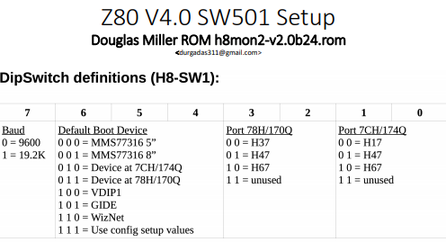
Just so I understand, you say that (reading switch 501 settings left to right) “Closed Open Closed Closed Open Open Open Closed” equates to 01110010, so that means “closed”=0, “open”=1, and you’re reading the bits right to left? It is confusing… I’m trying to use the guide in the jumper settings doc but it’s still confusing to me. Terry S. tells me he’s planning to rework this to clarify. It shows:

So that’s why I used “Open Closed” (10) to specify the H67. Or am I supposed to read these bits right to left too?
Anyway I did switch to “closed open” on the leftmost two switches. Same result, returns to monitor whenever I boot (either Boot EE-00 or front panel universal results the same: brief I/O on the H67 controller port and returns to monitor with a beep.)
Just as a reminder, in case it helps with diagnosis, if I swap out the V4 CPU/MMU boards for the equivalent previous versions (CPU3.1/MMU1.0) the system boots CP/M3 fine off the image I had been using. I haven’t tried booting the old boards off the newer image posted on Norberto’s site but I could if that helps.
From: se...@googlegroups.com <se...@googlegroups.com> On Behalf Of Douglas Miller
Sent: Sunday, June 13, 2021 8:13 AM
To: se...@googlegroups.com
Subject: Re: [sebhc] Rev 4.0 CPU - it's alive!
Just to be certain I'm testing the same thing, I think your dipswitches must actually be (left to right, bit 0 to bit 7, pin 1:16 to 8:9):
Closed Open Closed Closed Open Open Open Closed
7CH=H67 78H=H37 Use config settings 9600 baud console
i.e. binary pattern 01110010. Otherwise, you should get an error from the monitor when trying "Boot EE-". Although, I don't have your ROM config settings so can't be certain if there's some confusion introduced by that.
Be aware, that the "Use config settings" setting refers to the default boot device, not device port settings. The ROM/flash device ports settings augment the dipswitches, but do not override them. Additionally, the OSes do not have access to the ROM config page and so rely on information provided by the dipswitches (or left behind by the ROM). CP/M 3 assumes that the H67 is at port 274Q (0BCH) if there is no "H67" specified in the dipswitches. If bit 0 of the dipswitches was actually "1", then the dipswitches would have been saying that an H47 was at port 7CH, not an H67. If your ROM config settings were saying that an H67 was at port 7CH, that would be a mistake. Right now, the ROM setup code does not exhaustively check for conflicts. We might want to make it more draconian about that - perhaps (makes it harder to validate as you can't check when each setting is made, but have to check before committing the setup page to flash).
On 6/12/21 8:22 PM, glenn.f...@gmail.com wrote:
H67 on 7C; H37 on 78.
SW501 is set as follows from left to right (with my interpretation/understanding shown below)
Open Closed Closed Closed Open Open Open Closed
7CH=H67 78H=H37 Use config settings 9600 baud console
SW1 on the MMU card has all the switches Closed (“on”).
I normally boot from the front panel via 4-key “universal” boot:
1. (boot)
To view this discussion on the web visit https://groups.google.com/d/msgid/sebhc/f5698252-1cbf-3150-474a-ecfd79e80c3c%40gmail.com.
Terry Smedley
Douglas Miller
The ROM documentation shows the dipswitches in conventional numeric form: MSB first/left. The fields are also defined MSB first/left. This CPU boards follows the convention of closed switches meaning logic "0" (although not all hardware does). Depending on what part you bought, your dipswitch housing may be marked with open/closed or "1"/"0" or possibly something/nothing else, as well as possibly "0".."7" or "1".."8" for each position. Orientation of the dipswitch on the PCB determines whether any markings are valid. Typically, a PCB is laid out with a particular dipswitch (family) in mind. I see that this CPU board is laid out with bit 0 of SW1 on the left, when viewed from the front with the buss connectors on the right.
Again, each field must be interpreted according to the
orientation you are using. In this case, bit 0 is the leftmost
switch so needs to be closed in order to be "0" for H67. Bit 1 is
the next-leftmost, and needs to be open. So, "closed open" for
this field.
I'm not reproducing any problem on the simulator, so it would seem that either I don't have your environment duplicated yet because I don't have all the settings and images, or else there is a hardware issue. If you have the ability to read the ROM image and send that to me, that might help. It's also possible that the CP/M 3 image has issues, in the boot code, and so maybe point me to where you got those. I was using the image: http://sebhc.durgadas.com/mms89/images/cpm3-512k-z37-rtc-rd.z67ide.xz
Terry, there is also an H17+H67 image at: http://sebhc.durgadas.com/mms89/images/cpm3-512k-z17-rtc-rd.z67ide.xz
To view this discussion on the web visit https://groups.google.com/d/msgid/sebhc/003501d76062%24ff63efc0%24fe2bcf40%24%40gmail.com.
glenn.f...@gmail.com
Thanks for all the clarification Douglas. I downloaded your cpm3-512k-z37-rtc-rd.z67ide image and burned that to a CF disk and was able to boot it The first time I tried the system seemed to be “hung” but subsequently it worked. Perhaps the system was formatting the L: drive? Anyway thank you for the help and clarification.
Terry: its worth clarifying some of this in the “jumpers/settings” document…
Logfile attached….
Norberto: its possible I made an error somewhere but I had been trying to use the image from koyado.com: CPM3_H37_H67_RTC_1GB.imgc.zip (H37/H67/RTC) at http://koyado.com/Heathkit/H8-512KB_RAM_MMU-v40.html. When I used Douglas’ image, and once I understood the DIP switch settings I was able to get things to work…
Tx!
To view this discussion on the web visit https://groups.google.com/d/msgid/sebhc/c6792a83-eba0-34d0-a762-7a018d303045%40gmail.com.
norberto...@koyado.com
The image on that website is for port 174Q. You need to use Douglas new image for port 274Q.
Let me do a dump of my ROM setup to support three boards at the same time (H17/H67/H37). Other will have same issue as well.
Thanks,
Norberto
To view this discussion on the web visit https://groups.google.com/d/msgid/sebhc/007201d76072%247a8f7840%246fae68c0%24%40gmail.com.
Douglas Miller
I can't use imgc files, or I would try that on the simulator.
To view this discussion on the web visit https://groups.google.com/d/msgid/sebhc/000001d7607c%242d9d1740%2488d745c0%24%40koyado.com.
Terry Smedley

Steven Hirsch
> I can't use imgc files, or I would try that on the simulator.
>
image. Find them here:
https://www.dropbox.com/sh/myghp6u2judz5jt/AAAAV52RP41YfDn2NG2_Ly7Xa?dl=0
Let me know if there any I missed?
Douglas Miller
describes. It appears to be a very old version of the bootloader, not
suitable for this ROM version.
Glenn Roberts
-----Original Message-----
From: se...@googlegroups.com <se...@googlegroups.com> On Behalf Of Douglas Miller
Sent: Sunday, June 13, 2021 4:32 PM
To: se...@googlegroups.com
Subject: Re: [sebhc] Rev 4.0 CPU - it's alive!
You received this message because you are subscribed to the Google Groups "SEBHC" group.
To unsubscribe from this group and stop receiving emails from it, send an email to sebhc+un...@googlegroups.com.
Glenn Roberts
So this week I’ve completed the build of the new Rev. 4.0 Z80 CPU board as well as the companion 512K RAM/MMU board. If you’ve read some of the posts here then you’ve heard how that went (mostly very well!). Basically the CPU board is a very complicated one but if you take your time and triple check your work you’ll be rewarded with a fine new capability for the H8. The MMU is likely mostly of interest to CP/M Plus users as it allows you to create a RAM drive but also lets you use the banked memory features of CP/M Plus. We’ve had some early discussions about the possibility of a RAM drive for HDOS but so far no work has been done there.
I have posted updated pictures in my Google album
https://photos.app.goo.gl/qPnUgEWNPEwxy3UL7
the first 5 pictures there are of the 8255 PIO board that I previously built. The rest are related to the CPU and MMU build. I currently have it configured in a 3-board setup with the CPU, MMU and the H37/67 I/O board I built earlier this spring. The Z67-IDE+ provides disk storage and is housed in a re-purposed old Heat/Zenith floppy disk drive cabinet. This is a complete and very capable system. I have also built the DUART companion board for the CPU including the VDIP1 USB host adaptor.
I want to shout out to Norberto Collado, Douglas Miller, Terry Gulczynski, and Terry Smedley for their skill and teamwork in bringing this together and testing and documenting their work and of course Todd Goodman for helping us manage the board production process. Great work guys!
I have been able to run HDOS 2.0 and CP/M Plus on this configuration and Terry S. has also run CP/M 2.2.04. I haven’t tried HDOS 3.0 yet but certainly don’t anticipate any issues.
The new features in the ROM are quite innovative. I particularly appreciate the integration of the USB/Flash interface via the VDIP1 module. The ROM can “boot” right into any program or utility on the flash drive, allowing you to (for example) test the 512K ram board. the ROM function is now in EEPROM so can be easily updated (another thing you can do from the USB flash drive!) and includes functionality from both the Heath and Magnolia worlds. You can even run the system entirely from the terminal monitor without the need to use the front panel, if that meets your need.
I know that Terry S. is working on updating and clarifying some of the documentation (e.g. jumper and switch settings) so watch for that update soon.
Gery Kissel has weighed in on his progress and I hope that others in the group are looking forward to building out this board. It’s an interesting and rewarding challenge!
- Glenn
Norberto Collado
Thanks Glenn! As always, I enjoyed the pictures. It was all about “team” work to re-energized the H8 into doing more interesting things. As you mentioned, a 3-board high quality configuration can give a better capable system for years to come.
Also I want to thank you as well for the USB VDIP1 HDOS and CP/M support to be able to transfer files easily between the PC and the H8 system.
Thanks,
Norberto
From: "se...@googlegroups.com" <se...@googlegroups.com> on behalf of Glenn Roberts <glenn.f...@gmail.com>
Reply-To: "se...@googlegroups.com" <se...@googlegroups.com>
Date: Sunday, June 13, 2021 at 7:11 PM
To: "se...@googlegroups.com" <se...@googlegroups.com>
Subject: RE: [sebhc] Rev 4.0 CPU - it's alive!
So this week I’ve completed the build of the new Rev. 4.0 Z80 CPU board as well as the companion 512K RAM/MMU board. If you’ve read some of the posts here then you’ve heard how that went (mostly very well!). Basically the CPU board is a very complicated one but if you take your time and triple check your work you’ll be rewarded with a fine new capability for the H8. The MMU is likely mostly of interest to CP/M Plus users as it allows you to create a RAM drive but also lets you use the banked memory features of CP/M Plus. We’ve had some early discussions about the possibility of a RAM drive for HDOS but so far no work has been done there.
--
You received this message because you are subscribed to the Google Groups "SEBHC" group.
To unsubscribe from this group and stop receiving emails from it, send an email to sebhc+un...@googlegroups.com.
To view this discussion on the web visit https://groups.google.com/d/msgid/sebhc/02a901d760c2%249ded8570%24d9c89050%24%40gmail.com.
Norberto Collado
Attached is my Z80 v4 configuration file to support three controllers at the same time.
Thanks,
Norberto
To view this discussion on the web visit https://groups.google.com/d/msgid/sebhc/000001d7607c%242d9d1740%2488d745c0%24%40koyado.com.
glenn.f...@gmail.com
FYI I did go back and try booting my “old” (Rev 3.1 Z80) CPU board using the CP/M Plus image that works with the Rev 4 version and verified that they are “backwards compatible”. I’m guessing the version of CP/M Plus that I had with the 3.1 board has the older boot loader technology Douglas referred to, so I will standardize on the latest one from him. I believe the version I was using dates back two years or so?
Also a question or comment about the new ROM image and the “Terminal” function that’s built in. my understanding is this functions as a “pass thru” allowing the H19 to be echoed out to port 330Q. I believe the old convention was 340Q was the serial printer port and 330 was the modem port? Recently we’ve been using 320 for the parallel printer port?
But I note that the new CPU board lets you jumper the second serial port to either 340 or 320, not 330? So the “terminal” function would seem to be usable only on systems that have a full H-8-4 serial card? Perhaps we could make the port number for the “terminal” function user-selectable via the “Configure” function?
- Glenn
From: se...@googlegroups.com <se...@googlegroups.com> On Behalf Of Douglas Miller
Sent: Sunday, June 13, 2021 8:24 AM
To: se...@googlegroups.com
Subject: Re: [sebhc] Rev 4.0 CPU - it's alive!
I tried this on the simulator, using dipswitch settings that say port 7CH is an H47, but ROM config saying that the H67 port is (also) 7CH. In that case I am able to start the CP/M 3 boot, but it fails with explicit errors:
H8: Boot EE-
Z89/Z90 Loader v2.241g (c) 1982,1983 Magnolia Microsystems
Bdos Err On A: Bad Sector
Bdos Err On A: Bad Sector
error: File not found: CPM3.SYS
which is to be expected as the CP/M 3 BIOS (which no longer has access to ROM data) checks the dipswitches, finds no H67 and assumes port 0BCH, and is unable to communicate with any device.
I'm resisting making (and maintaining) a special version of CP/M 3 for the newer ROM (CPU boards). I'd like it to remain backward-compatible with older ROMs.
On 6/13/21 7:13 AM, Douglas Miller wrote:
Just to be certain I'm testing the same thing, I think your dipswitches must actually be (left to right, bit 0 to bit 7, pin 1:16 to 8:9):
Closed Open Closed Closed Open Open Open Closed
7CH=H67 78H=H37 Use config settings 9600 baud consolei.e. binary pattern 01110010. Otherwise, you should get an error from the monitor when trying "Boot EE-". Although, I don't have your ROM config settings so can't be certain if there's some confusion introduced by that.
Be aware, that the "Use config settings" setting refers to the default boot device, not device port settings. The ROM/flash device ports settings augment the dipswitches, but do not override them. Additionally, the OSes do not have access to the ROM config page and so rely on information provided by the dipswitches (or left behind by the ROM). CP/M 3 assumes that the H67 is at port 274Q (0BCH) if there is no "H67" specified in the dipswitches. If bit 0 of the dipswitches was actually "1", then the dipswitches would have been saying that an H47 was at port 7CH, not an H67. If your ROM config settings were saying that an H67 was at port 7CH, that would be a mistake. Right now, the ROM setup code does not exhaustively check for conflicts. We might want to make it more draconian about that - perhaps (makes it harder to validate as you can't check when each setting is made, but have to check before committing the setup page to flash).
On 6/12/21 8:22 PM, glenn.f...@gmail.com wrote:
H67 on 7C; H37 on 78.
SW501 is set as follows from left to right (with my interpretation/understanding shown below)
Open Closed Closed Closed Open Open Open Closed
7CH=H67 78H=H37 Use config settings 9600 baud console
SW1 on the MMU card has all the switches Closed (“on”).
I normally boot from the front panel via 4-key “universal” boot:
1. (boot)
To view this discussion on the web visit https://groups.google.com/d/msgid/sebhc/6d7b358b-2568-223f-8e1c-16221c0bb70c%40gmail.com.
Terry Smedley
Douglas Miller
One comment, for consideration. The dipswitch settings are ultimately determined by the ROM. I believe there will be other ROMs made available for this board, and those may not use the dipswitches that exact same way. It may be better to refer the user to the documentation for their ROM in order to set the dipswitches.
--
You received this message because you are subscribed to the Google Groups "SEBHC" group.
To unsubscribe from this group and stop receiving emails from it, send an email to sebhc+un...@googlegroups.com.
To view this discussion on the web visit https://groups.google.com/d/msgid/sebhc/195f8a27-d88a-40f1-996a-ba88e46b07dbn%40googlegroups.com.
glenn.f...@gmail.com
Continuing to configure/test the Rev. 4.0 configuration and CP/M Plus. I have successfully moved my files over from the 3.1 configuration using a floppy drive to copy the VDIP utilities, then using VPIP and the USB/Flash drive capability.
I am tracking a problem that has shown up several times. It seems to happen after I’ve been using the system for a while, however I do not believe this is heat related because: 1) the system runs very cool and 2) resetting the system (power cycling) solves the problem.
The symptom is I do a directory on the I: drive (first 3.5” floppy) and receive:
C>dir i:
CP/M Error On I: Invalid Drive
BDOS Function = 17 File = ????????.???
C>
I should note that the floppy drive has been working fine when I first boot. If I then repeat the command the system hangs with the ION and MON LEDs out (RUN and PWR lit). if I reset from the front panel it begins to boot but I do not get to the command prompt. If I physically power cycle everything I can get it all to work fine. I’ve observed this sequence three times.
C>dir i:
ß system hangs, MON and ION LEDs out. Reboot from front panel...
H8 Monitor v2.0(beta24)
H8:
Z89/Z90 Loader v2.241g (c) 1982,1983 Magnolia Microsystems
BNKBIOS3 SPR F200 0E00
BNKBIOS3 SPR 9800 2800
RESBDOS3 SPR EC00 0600
BNKBDOS3 SPR 6A00 2E00
59K TPA
ß No command prompt. Must power cycle to get it back…
This seems to be repeatable. I will track and gather more data and post a follow up… I will also configure HDOS on this machine and see if I see anything similar.
Also a question: do we have a SHUTDOWN command that will bring the system back to the monitor (e.g. for operation without a front panel)? Similarly is there a REBOOT.COM? tx.
- Glenn
Glenn Roberts
Begin forwarded message:
From: Glenn Roberts <glenn.f...@gmail.com>
Date: June 19, 2021 at 7:19:49 PM EDT
To: glenn.f...@gmail.com
Subject: Re: [sebhc] Rev 4.0 CPU - it's alive!
Just had a thought. I think I brought over a PROFILE.SUB file. Perhaps there is a command in there setting the CPU speed to 10Mhz. That would cause floppy access to break. Will investigate…Sent from my iPadOn Jun 19, 2021, at 6:42 PM, glenn.f...@gmail.com wrote:
norberto.collado koyado.com
Sent: Saturday, June 19, 2021 3:42 PM
To: se...@googlegroups.com <se...@googlegroups.com>
glenn.f...@gmail.com
It looks like a dumb mistake on my part. I think at some point I had a PROFILE.SUB in there that set the speed to 10, which caused floppys to not work. I know ken has a BIOS workaround for this but I use floppys so rarely im happy to step down to 2mhz when needed. So I didn’t realize the system was running fast.
I think I saw one of the features Norberto is putting into his new multi-function board is a CPU speed indicator? That will be handy (I have that on Rusty, which uses the older multi-board solution for CPU speed control).
To view this discussion on the web visit https://groups.google.com/d/msgid/sebhc/SN6PR01MB3855F13392E8045B0B442C1EF70B9%40SN6PR01MB3855.prod.exchangelabs.com.
Terry Smedley
norberto...@koyado.com
Glenn,
As described by Terry’s email, the new H8 FP has more LEDS; the original 5mm and the new ones 3mm to display CPU speed and any other I/O activity. The SSI board will drive the H8 front panel speed LED’s.
There is a total of 10 LED’s.

Thanks,
Norberto
To view this discussion on the web visit https://groups.google.com/d/msgid/sebhc/cf7cf0af-e678-4221-a0e8-304dab573646n%40googlegroups.com.
Glenn Roberts
Very nice. the four color LED is a cool approach! also the idea of an external display gets one thinking – Large 7Segment LED display? Nixie tubes? Larger colored lights in a box? A “DEFCON five” type display? Maybe even an old fashioned analog meter…
To view this discussion on the web visit https://groups.google.com/d/msgid/sebhc/cf7cf0af-e678-4221-a0e8-304dab573646n%40googlegroups.com.