D1 LED indicator on DUART-16C550/USB daughterboard

glenn.f...@gmail.com
Norberto: on the DUART/USB daughterboard the D1 LED indicator is wired to “LED1” on the VDIP-1, which is the activity indicator for USB port #1. The only problem is our main use of the USB has been for file transfer to/from USB Flash Drives, or what the FTDI folks call Bulk Only Mass Storage (BOMS). With the FTDI VDAP firmware that we use BOMS transfers are only supported on the on-board USB port, which is actually port #2! See table 3.1 in:
https://www.ftdichip.com/Firmware/Precompiled/UM_VinculumFirmware_V205.pdf
I plan to do a rework on my boards to connect D1 to the port2 (LED2) monitor position on the VDIP1. While there is a small activity indicator (SMT LED) for port 2 on the VDIP device itself, it’s not generally visible when the board is in the chassis.
While we have looked at some possible uses for port 1 we have not had much success finding one. A few of us experimented with trying to print from that port but found it difficult to program… so I don’t see value in monitoring LED1…
- Glenn
glenn.f...@gmail.com
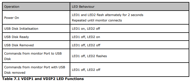
I have applied the rework to both of my DUART/USB daughterboards and D1 now accurately reflects USB traffic to/from the USB drive. From the Vinculum documentation here’s how to interpret the LEDs:
For those of you who use my “Vinculum” utilities: I’m trying to understand an issue with VPUT, which is used to move files from the H8 onto the USB. The issue is also in VPIP when used in this “put” mode. There is some kind of timing issue that causes the first “put” operation to either take a long time or fail. Subsequent invocations seem to work correctly. During this failure mode the VDIP-1 seems to be in some kind of wait mode with the LED2 diode flashing (this is a very steady flashing vs. the more random flashing seen when there’s I/O being performed). The workaround is to re-issue the command but I would like to figure out what’s going on. if I can solve the problem I’ll update the software, which is available in the software section on Les’ Github:
https://sebhc.github.io/sebhc/software.html (search for “Vinculum”)...
the biggest issues I dealt with in writing the Vinculum utilities were timing related. Since it’s an ASCII-based command protocol, and there are wide variations in response times to some commands, it is hard to get a robust and error-free back-and-forth… early versions of the program would often hang, so I had to add time-outs, but getting those right is a challenge.

norberto.collado koyado.com
Sent: Monday, September 5, 2022 2:52:03 PM
To: se...@googlegroups.com <se...@googlegroups.com>
Subject: [sebhc] RE: D1 LED indicator on DUART-16C550/USB daughterboard
You received this message because you are subscribed to the Google Groups "SEBHC" group.
To unsubscribe from this group and stop receiving emails from it, send an email to sebhc+un...@googlegroups.com.
To view this discussion on the web visit https://groups.google.com/d/msgid/sebhc/05c901d8c12e%24ae1ea550%240a5beff0%24%40gmail.com.
glenn.f...@gmail.com
Just cut the trace leading to pin 2 (LED1) and move the connection to pin 3 (LED2) on the VDIP-1 socket.
To view this discussion on the web visit https://groups.google.com/d/msgid/sebhc/SN6PR01MB38556A59DEC089C1D6DC4A2DF77F9%40SN6PR01MB3855.prod.exchangelabs.com.
glenn.f...@gmail.com
For anyone using the USB via the H17 piggyback board here is the rework I did on mine to make the LED indicate traffic on the VDIP-1 (LED2)
https://photos.app.goo.gl/nVV5YsZSDjSHEY1o6
cut through the small trace going to pin 2 and then add a connection from pin 3 to the LED cathode…