HA8-3 Color Graphics games - blast from the past

Les Bird

norberto.collado koyado.com
Sent: Thursday, August 26, 2021 2:45 PM
To: SEBHC <se...@googlegroups.com>
Subject: [sebhc] HA8-3 Color Graphics games - blast from the past
You received this message because you are subscribed to the Google Groups "SEBHC" group.
To unsubscribe from this group and stop receiving emails from it, send an email to sebhc+un...@googlegroups.com.
To view this discussion on the web visit https://groups.google.com/d/msgid/sebhc/4504862e-7db6-492b-abdd-a7ab34dc458fn%40googlegroups.com.

Steven Feinsmith
It may be nice to recreate the HA8-3 along with your Warlords software.
To view this discussion on the web visit https://groups.google.com/d/msgid/sebhc/SN6PR01MB3855F2A48410879D88AA4EEBF7C79%40SN6PR01MB3855.prod.exchangelabs.com.
norberto.collado koyado.com
Sent: Thursday, August 26, 2021 3:17 PM
To: se...@googlegroups.com <se...@googlegroups.com>
Subject: Re: [sebhc] HA8-3 Color Graphics games - blast from the past

Glenn Roberts
On Aug 26, 2021, at 7:47 PM, norberto.collado koyado.com <norberto...@koyado.com> wrote:
To view this discussion on the web visit https://groups.google.com/d/msgid/sebhc/SN6PR01MB3855B2FED1DC9D5CB427571DF7C79%40SN6PR01MB3855.prod.exchangelabs.com.
Les Bird

Douglas Miller
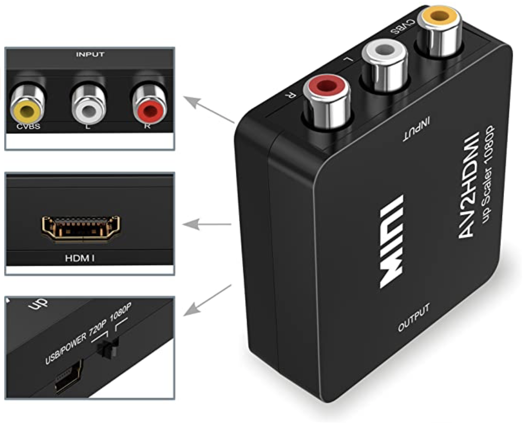
I'm guessing there must be modern chips/modules that produce HDMI output? That can include audio as well.
To view this discussion on the web visit https://groups.google.com/d/msgid/sebhc/0c0b9869-c901-4bf1-8b8b-4d259ceaf988n%40googlegroups.com.
Steven Feinsmith
https://www.ebay.com/itm/363474411197?hash=item54a0c35ebd:g:W70AAOSw-0xYNxFF
or
https://www.ebay.com/itm/403008599134?hash=item5dd52f345e:g:aCMAAOSwmg1gNiIw
I am not sure if I may have a schematic for the HA8-3. I have to search for it here or at my storage place. In case I may have it, then I will post it here.
To view this discussion on the web visit https://groups.google.com/d/msgid/sebhc/0c0b9869-c901-4bf1-8b8b-4d259ceaf988n%40googlegroups.com.
norberto.collado koyado.com
Steven Feinsmith
To view this discussion on the web visit https://groups.google.com/d/msgid/sebhc/SN6PR01MB38552F976E6AAEC142EA0666F7C89%40SN6PR01MB3855.prod.exchangelabs.com.
Norberto Collado
Thanks Steven!
Based on documentation, it is almost the same as the SSI board that Terry S. put together. It just needed the Video Display Processor. It should be easy to recreate once schematic is available.
Norberto
To view this discussion on the web visit https://groups.google.com/d/msgid/sebhc/CAGJMgmW_xxgwDsRhAm3H8o1DZuvaVda5Jbvn59%2ByfxNdDz4uNA%40mail.gmail.com.
Norberto Collado
So this adapter will work fine with it.
Glenn, Terry S. is the expert on joystick.
To view this discussion on the web visit https://groups.google.com/d/msgid/sebhc/0c0b9869-c901-4bf1-8b8b-4d259ceaf988n%40googlegroups.com.
Glenn Roberts
So this adapter will work fine with it.
Glenn, Terry S. is the expert on joystick.
<image001.png>
To view this discussion on the web visit https://groups.google.com/d/msgid/sebhc/A8C87142-A2DE-4B77-8715-20ED5D082228%40koyado.com.
Les Bird
glenn.f...@gmail.com
I can post to the site but initially here’s the update to my google photos account.
Schematics:
https://photos.app.goo.gl/S2Qmorpf48eoMX8a8
https://photos.app.goo.gl/GEYy2xZEpVh7UbvG7
board shots:
https://photos.app.goo.gl/uifwGNuShhUvuYjH8
https://photos.app.goo.gl/xPE7J5xrsfpsoJND9
https://photos.app.goo.gl/UgHW8pcVK5bymuxj6
the empty socket is for the math co-processor (I have one, it’s just not installed in this shot).
I have no additional documentation. The manual on the site appears to be complete (in fact it’s a newer version than I have…)
To view this discussion on the web visit https://groups.google.com/d/msgid/sebhc/e8e9265a-723a-4673-a6ce-166ff807a391n%40googlegroups.com.
norberto.collado koyado.com
Sent: Friday, August 27, 2021 3:14 PM
To: se...@googlegroups.com <se...@googlegroups.com>
Subject: RE: [sebhc] HA8-3 Color Graphics games - blast from the past
glenn.f...@gmail.com
The second link under schematics contains a table of all the semiconductors. The transistors are 2N2222As. The ones on my board are in a TO-18 case, e.g.:
To view this discussion on the web visit https://groups.google.com/d/msgid/sebhc/SN6PR01MB38556971A321589E90A500DEF7C89%40SN6PR01MB3855.prod.exchangelabs.com.
Steven Feinsmith
To view this discussion on the web visit https://groups.google.com/d/msgid/sebhc/003001d79b90%24ef57e5f0%24ce07b1d0%24%40gmail.com.
glenn.f...@gmail.com
Might have to go to the video game hobby sites to track down some of these old chips… (arcadepartsandrepair, quest, etc.)
To view this discussion on the web visit https://groups.google.com/d/msgid/sebhc/CAGJMgmW0J1sCSxA0LQqEPQKFQZUHMQ_r9rtE9wLV%3DMi6u3Oetw%40mail.gmail.com.
glenn.f...@gmail.com
Also a reminder: the default board configuration uses ports in the 270Q-276Q range, which could interfere with the Z67 in its alternate configuration. I’m just now getting back up to speed on that. It may be only the Arithmetic Processor that represents a direct conflict as that uses 274Q by default. Changing the board is possible but involves cutting traces and soldering wires (no jumpers!)
Since the 274Q configuration for the Z67 was not the Heath “standard” I guess this wasn’t an issue back then, but today many of us use 274 so that we can keep 174 for the H17 and 170 for the H37. It’s all workable but you need to plan the configuration carefully….
To view this discussion on the web visit https://groups.google.com/d/msgid/sebhc/SN6PR01MB38556971A321589E90A500DEF7C89%40SN6PR01MB3855.prod.exchangelabs.com.
Glenn Roberts
Well, I seem to be able to reproduce your demo Les.
https://photos.app.goo.gl/PeJSiXF9Soaa2JFH9
do you recall if the controllers are analog (e.g. paddles) or contact (e.g. joystick up/down/left/right) based? I suppose I can scrutinize the source and figure that out…
sound works great. “gunshot” sounds whenever the sprite hits a wall.
From: se...@googlegroups.com <se...@googlegroups.com> On Behalf Of Les Bird
To view this discussion on the web visit https://groups.google.com/d/msgid/sebhc/0c0b9869-c901-4bf1-8b8b-4d259ceaf988n%40googlegroups.com.
norberto...@koyado.com
WOW! Great work! If we can source same IC’s then we can reproduced the board, except the 4116 RAM which can be replaced with a single 32K IC.
Thanks for sharing,
Norby
To view this discussion on the web visit https://groups.google.com/d/msgid/sebhc/000001d79d1a%245b3bb870%2411b32950%24%40gmail.com.

Dave McGuire
> WOW! Great work! If we can source same IC’s then we can reproduced the
> board, except the 4116 RAM which can be replaced with a single 32K IC.
and controls 4116s directly, including directly driving the RAS and CAS
lines. It would take some logic to put a modern SRAM on it, I think.
-Dave
--
Dave McGuire, AK4HZ
New Kensington, PA

Terry Smedley
Glenn Roberts
On Aug 29, 2021, at 6:34 PM, Terry Smedley <terry....@gmail.com> wrote:
As Steven pointed out, there are sources for the video and sound chips. There's one eBay seller (Hong Kong) that specializes in kitting chipsets for retro builds. I have submitted a request for an "HA-8-3" kit with the TMS9918, AY3-8910, AD7574, and AD7501 chips. Those are all available independently, but we'll see what this seller comes up with for a set.
To view this discussion on the web visit https://groups.google.com/d/msgid/sebhc/d6e0f839-9904-400d-b779-30e105695972n%40googlegroups.com.
Steven Feinsmith
http://www.s100computers.com/My%20System%20Pages/VGA%20Board/VGA%20Board.htm
What do you think?
Steven
To view this discussion on the web visit https://groups.google.com/d/msgid/sebhc/C8388986-F4F2-48DE-B63D-B059548B51E8%40gmail.com.
norberto...@koyado.com
-----Original Message-----
From: se...@googlegroups.com <se...@googlegroups.com> On Behalf Of Dave McGuire
Sent: Sunday, August 29, 2021 3:29 PM
To: se...@googlegroups.com
Subject: Re: [sebhc] HA8-3 Color Graphics games - blast from the past
Dave McGuire
Ah, that's a neat idea. I bet that'll work nicely!
-Dave
Les Bird
Glenn Roberts
Great! I’ll try those next. I’ll also look through the archives. I see, for example, color graphics references in some HUG disks (885-1098 and 1099).
--
You received this message because you are subscribed to the Google Groups "SEBHC" group.
To unsubscribe from this group and stop receiving emails from it, send an email to sebhc+un...@googlegroups.com.
To view this discussion on the web visit https://groups.google.com/d/msgid/sebhc/74ed0bae-7c22-4e56-a605-75821ee32d3fn%40googlegroups.com.
Les Bird
Dave McGuire
> The HA8-3 board was designed back in the late 1970 or early 1980s. The
> video resolution was limited during the old days. The Texas Instrument
> 9918 (1979) was advanced and made everything simple and minimum cost as
> affordable. Nowadays, we are more advanced in video controllers. I
> assume it is okay to re-create the board. Then, we can seek to create a
> new generation of video board that use semi-modern video controllers
> such as Trident TVGA9000i-3. This chip is used on the S-100computers.com
> board. Please see:
>
> http://www.s100computers.com/My%20System%20Pages/VGA%20Board/VGA%20Board.htm
find.
An alternative might be the NEC uPD7220. It's less capable than the
TVGA9000, but it's a whole lot more capable than the TMS9918. And
they're easy to find, and not too difficult to apply.