H17 Floppy Drive RAW Read/Write Z80 Controller!

norberto.collado koyado.com

Douglas Miller
Interesting project. So, the floppy drive is just decoration? The
"media" is some storage device (SD, CF, ...) attached to the Z80?
There would be no diskette in the drive - or at least no diskette
that contains data? I know the MAME simulators have gone overboard
(or not?) with simulating audio, and have a lot of audio clips for
floppy drives - maybe just add a speaker (and audio circuitry) and
leave the drive dead (except for LED)?
As I recall, the motor might be a bit tricky. But if you only
need to approximate RPM then maybe it can be simplified. Just a
matter of some analog circuitry. Does head load exist on 5"
drives? The ones I remember were always loaded - it was the 8"
drives that actually loaded/unloaded the heads. LED should be
pretty basic, I presume.
I suppose it doesn't need to actually be a Z80 in the controller,
either? Could be an rPi running Linux?
--
You received this message because you are subscribed to the Google Groups "SEBHC" group.
To unsubscribe from this group and stop receiving emails from it, send an email to sebhc+un...@googlegroups.com.
To view this discussion on the web visit https://groups.google.com/d/msgid/sebhc/SN6PR01MB3855559485F1C6125F63BAB4F7189%40SN6PR01MB3855.prod.exchangelabs.com.

Glenn Roberts
On Jul 9, 2021, at 5:21 PM, Douglas Miller <durga...@gmail.com> wrote:
Interesting project. So, the floppy drive is just decoration? The "media" is some storage device (SD, CF, ...) attached to the Z80? There would be no diskette in the drive - or at least no diskette that contains data? I know the MAME simulators have gone overboard (or not?) with simulating audio, and have a lot of audio clips for floppy drives - maybe just add a speaker (and audio circuitry) and leave the drive dead (except for LED)?
As I recall, the motor might be a bit tricky. But if you only need to approximate RPM then maybe it can be simplified. Just a matter of some analog circuitry. Does head load exist on 5" drives? The ones I remember were always loaded - it was the 8" drives that actually loaded/unloaded the heads. LED should be pretty basic, I presume.
I suppose it doesn't need to actually be a Z80 in the controller, either? Could be an rPi running Linux?
On 7/9/21 3:09 PM, norberto.collado koyado.com wrote:
I started years ago on the idea to modify a bad H17 floppy drive to be controlled by a Z80 controller. The Z80 controller will communicate with the H17 controller, to read/write data to on-board RAM with battery backup. Also, it will control the floppy drive spindle, track zero detector, diskette media detector, and to be able to seek between tracks.
I have several 5.25" bad floppy drives that I can use. The idea is to have the same feel and look like the original floppy drive. You just insert a floppy diskette and then the Z80 will emulate all floppy conditions. It is more like having the SVD-III controlling a real floppy drive.
The idea for using the Z80 is to use all the H17 code without the need to re-write that much. The goal is for my personal learning on floppy technology especially for the H17 controller as is the easy one to tackle. Also, to keep my H17 enclosure as original.
My question is: How easy is to interface to the floppy cables that controls the motors? I'm looking for a simple circuit design that can spin the floppy media (ignore RPM's), head load, and control the seek operation. The sensors should be easy to do (track Zero and floppy media presence) + drive LED.
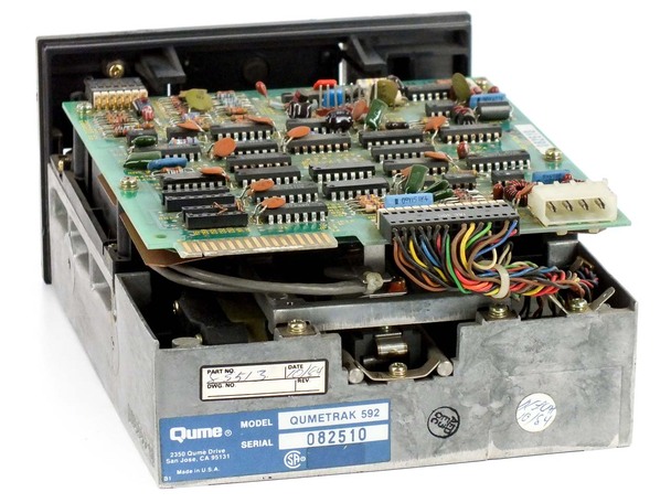
This is the floppy drive that I have, and this will be next year project depending on how easy is to interface. I just want to take out the top board and insert the Z80 controller board and plug in the cables.
<DSCF0487__44731.1572898937.jpg>
--
You received this message because you are subscribed to the Google Groups "SEBHC" group.
To unsubscribe from this group and stop receiving emails from it, send an email to sebhc+un...@googlegroups.com.
To view this discussion on the web visit https://groups.google.com/d/msgid/sebhc/SN6PR01MB3855559485F1C6125F63BAB4F7189%40SN6PR01MB3855.prod.exchangelabs.com.
--
You received this message because you are subscribed to the Google Groups "SEBHC" group.
To unsubscribe from this group and stop receiving emails from it, send an email to sebhc+un...@googlegroups.com.
To view this discussion on the web visit https://groups.google.com/d/msgid/sebhc/1d0a95d8-003d-477a-4d99-cb89eb3e68a6%40gmail.com.
Douglas Miller
I remember a DEC word processor with 8" drives (PDP-8 I believe)
that had virtually no head-load sustain timeout. Talk about a
cringe-worthy racket. It sounded terrible. At least HDOS and CP/M
kept the head loaded for awhile after an access. Wasn't head-load
tied to motor-on?
To view this discussion on the web visit https://groups.google.com/d/msgid/sebhc/60A58B90-F286-4999-ACFB-5BDDBAB56AE6%40gmail.com.

Dave McGuire
> I remember a DEC word processor with 8" drives (PDP-8 I believe) that
> had virtually no head-load sustain timeout. Talk about a cringe-worthy
> racket. It sounded terrible. At least HDOS and CP/M kept the head loaded
> for awhile after an access. Wasn't head-load tied to motor-on?
(Intersil 6100) on another board mounted inside. We have a pair of them
at LSSM.
-Dave
--
Dave McGuire, AK4HZ
New Kensington, PA
norberto.collado koyado.com
Sent: Friday, July 9, 2021 3:27 PM
To: se...@googlegroups.com <se...@googlegroups.com>
Subject: Re: [sebhc] H17 Floppy Drive RAW Read/Write Z80 Controller!

Mark Garlanger
--
norberto...@koyado.com
Good questions Mark. Let me put together a block diagram on what I want to create. The end goal is for learning purposes on how the H17 controller + floppy works. I think more like a companion to the Z67-IDE+ controller. If I can get it to work with the H17 controller, then I can create another board to do the same for the H37.
It is a RAW read/write SSD drive. You can format it with the OS and then do reads/writes as needed. I can use the Z80 v4 board to write H8D images to it and to create new H8D images as needed. All images will live on the VDIP1 USB flash drive. At this time I see it more like a Z80 with a lot of RAM and a big battery backup (along with the floppy I/O circuit). Not sure if a CF card or serial ports are needed at this time. A lot of endless possibilities…
Norberto
From: se...@googlegroups.com <se...@googlegroups.com> On Behalf Of Mark Garlanger
Sent: Friday, July 9, 2021 9:42 PM
To: se...@googlegroups.com
Subject: Re: [sebhc] H17 Floppy Drive RAW Read/Write Z80 Controller!
What is the end goal of the setup? Do you want to have these drives simulate in real-time what they would be doing if connected to your H8? If you are going to use the H17 code, you will have to at least do some emulation of the H17 controller (map ports, translate port accesses to signals on the cable, etc.). And how is the Z80 connected to the floppy drive, going to know what it should be doing at any given point? Have you considered doing something with the cabling coming from the H8, like splitting it to go to both the SVD and the physical drive?
To view this discussion on the web visit https://groups.google.com/d/msgid/sebhc/CAAjkm7_8proD9TGH8H1QRUV4AsZkfYEQjrcDS662LOe-Puzgug%40mail.gmail.com.
Douglas Miller
Thought of one more sound effect you need: stepper motor. More
analog circuitry, I believe.
I guess it depends on what has gone wrong with your "bad drives",
but do you really need to remove the existing drive electronics?
If you just used them to interface to the head load (if present),
motor, and stepper motor, that would make things a lot simpler. It
would make your Z80 board more universal as well.
To view this discussion on the web visit https://groups.google.com/d/msgid/sebhc/000001d7755b%24cfe9aab0%246fbd0010%24%40koyado.com.

Peter Higgins
norberto...@koyado.com
Thanks Peter for the feedback. I like Douglas’ idea to let the floppy board drive the logic and less work for the Z80 CPU. My definition of a bad floppy drive, is that everything works except the heads. No matter how much I clean the heads I cannot format or read from it. Everything else is functional.
Thanks,
Norberto
From: se...@googlegroups.com <se...@googlegroups.com> On Behalf Of Peter Higgins
Sent: Saturday, July 10, 2021 9:16 AM
To: SEBHC <se...@googlegroups.com>
Subject: Re: [sebhc] H17 Floppy Drive RAW Read/Write Z80 Controller!
Some thoughts on this project:
--
You received this message because you are subscribed to the Google Groups "SEBHC" group.
To unsubscribe from this group and stop receiving emails from it, send an email to sebhc+un...@googlegroups.com.
To view this discussion on the web visit https://groups.google.com/d/msgid/sebhc/22780591-c45e-46fd-8e98-f5747de139b1n%40googlegroups.com.