H8-2020

Glenn Roberts
I’ve been fixing up an old case that had been used by a previous owner as an H8 expansion chassis. In this day and age of $800+ H8 systems that seemed like a waste, so I plan to re-purpose this old chassis to house my “H8-2020” system (Z80 4.0 board, new backplane, LED front panel, etc.)
pix of the case rehab are here:
https://photos.app.goo.gl/wmuGRqjo1FPtq5Rz5
I used Bondo to patch the gaping slits that had been cut into the side panels (eventually I plan to replace these with wooden panels). I had to sand down the panels which removed the original “splattered” paint texture. I was unable to find a spray paint that would produce that look but I realized that I needed some texture to hide where I had patched the panel. I ended up using a “hammered” look paint from Rustoleum and then covering it with black satin. You can see the patch if you look (last few pictures) but it’s not particularly bothersome.
Now I need to complete the front panel assembly. I will also need a new backplane.
Norberto: what’s the status on the new backplane boards? I don’t see them in Todd’s inventory, so I presume they haven’t been released to production? Any estimate on that? it would be cool to show off the H8-2020 at VCF East which is 7 weeks from this Friday.
Tx.
- Glenn

Norberto Collado
Glenn,
Nicely done! The chassis looks great!
On the new backplane I need to fix hole positioning as it is off. It can be attached but it needs to be better. I will work on it this week.
As you will not be using the PC power supply, I can send you one of my prototype as it will work fine. Only a small wire will need to be added on side 2. To use current H8 power supply you cannot install pins on last H8 connector and you cannot install the PC 24-pin connector and any other component related to the PC power supply.
Let me know if you want me to ship one this week and I think I have extra parts for the H8 original parts (caps, resistors, etc.).
Thanks,
Norberto
--
You received this message because you are subscribed to the Google Groups "SEBHC" group.
To unsubscribe from this group and stop receiving emails from it, send an email to sebhc+un...@googlegroups.com.
To view this discussion on the web visit https://groups.google.com/d/msgid/sebhc/029901d79441%243817d4f0%24a8477ed0%24%40gmail.com.
Glenn Roberts
On Aug 18, 2021, at 11:29 AM, Norberto Collado <norberto...@koyado.com> wrote:
To view this discussion on the web visit https://groups.google.com/d/msgid/sebhc/60AA422E-7D29-4CAB-8CEC-7E391633566D%40koyado.com.
Norberto Collado
The proto board fully supports the PC power Supply. If using the PC power supply, no need to add wire on side 2.
To view this discussion on the web visit https://groups.google.com/d/msgid/sebhc/39C88052-668B-4B6A-92C1-B64040DF6B23%40gmail.com.

Mark Garlanger
--
Norberto Collado
Glenn’s system looks as described on such article. However they did not buffer the signal on both boards (just one end) and no buffering for the data bus and interrupts, so they were limited to max length of 18 inches between the two chassis forcing them to cut the chassis side panels.
The H8 expander board that I’m working on buffers the signal on both boards along with the data bus and interrupts lines. It uses the DB25 male to male cable connectors. To control the data bus, it uses a GAL to properly control the data bus. So adding a second chassis will look more like adding a controller board without signal degradation, hopefully.
Thanks for the article as it provide great feedback on this idea.
Norberto
To view this discussion on the web visit https://groups.google.com/d/msgid/sebhc/CAAjkm7_LZ%3DBUn4yP9P8JtUpHqJ323SKRisAEYyFABe4%2Bi_vo6A%40mail.gmail.com.
Glenn Roberts
Wow. Pulling up that Microcomputing issue took me down memory lane. Amazing how many little companies there were providing software and other stuff. It was a pretty amazing time. As I recall Microcomputing had quite a few articles on Heathkit computing. The Diablo printers caught my eye – they were $2,400 way back then. that was some serious money!
As for chassis expansions, other than the “cool” effect I see little practical need these days. Back then the big driver was memory boards. If you had started out with, say, a few 8K boards and then maybe graduated to 16K ones you could quickly fill up the 10 slots in the card cage. Today a single 64k board is all you need (or with the new CPU boards the RAM is built in). so I’ve not yet run into a situation where I can’t accommodate all the cards I need. Les’ backplane board even had extra slots which I’ve used occasionally to house smaller “half” and “quarter” boards.
From: se...@googlegroups.com <se...@googlegroups.com> On Behalf Of Mark Garlanger
Sent: Wednesday, August 18, 2021 10:25 PM
To: se...@googlegroups.com
Subject: Re: [sebhc] H8-2020
Hey Glenn,
To view this discussion on the web visit https://groups.google.com/d/msgid/sebhc/CAAjkm7_LZ%3DBUn4yP9P8JtUpHqJ323SKRisAEYyFABe4%2Bi_vo6A%40mail.gmail.com.
Mark Garlanger
To view this discussion on the web visit https://groups.google.com/d/msgid/sebhc/08fe01d7979c%248c83f6f0%24a58be4d0%24%40gmail.com.
Glenn Roberts
Awesome! The one I received was in some disrepair and (in my opinion) a bit of a haphazard attempt. Pic here:
https://photos.app.goo.gl/LdUVuDAX9QCPN2mG8
The more professional approach in the Kilobaud article would be more “museum worthy”.
To view this discussion on the web visit https://groups.google.com/d/msgid/sebhc/CAAjkm7_P_PYAqS7TTf%3D7eMaVMcmxvoJ%2B4M%2BJPOPnSnD68w8bvQ%40mail.gmail.com.
glenn.f...@gmail.com
It’s alive!
https://photos.app.goo.gl/mSyRdu1UNqhdvE8e9
Norberto sent me one of his prototype backplanes and after building it I installed the Rev. 4 CPU board and was able to bring it up without a front panel! A truly “bare bones” H8.
To reconfigure for stand alone operation (no front panel, no H37/67, no 512K RAM board) I made some jumper changes:
- Switched the H37 jumpers (JP17, JP200, JP201)
- Installed 74LS148 instead of H37 ribbon cable
- Moved JP19 to top (“DI”)
- Moved JP8 to left (“OFF”)
- Switched from 512K board to on board RAM (JP15 and JP18)
- Installed JP26 and JP27 to provide 12V direct from Power Supply
- Did not need to jumper around 7805s as I’m using Pololu step up/down regulators
Complete jumper descriptions are at:
http://koyado.com/Heathkit/H8-Z80-64K-RTC-ORG0-V4_files/Z80_V_4_0_Jumper_Definition_V02.pdf
the built in ROM is able to talk to the VDIP chip (USB flash drive):
https://photos.app.goo.gl/aC1faebiNAc6TpQt7
you can even run programs directly from the flash drive. In principle you could boot an OS this way using RAM drives but not sure if we’ve crossed that bridge yet?
This is the first operational version of my H8-2020 system. I am using an SFX form factor ATX power supply, $29.99 on Amazon:
https://www.amazon.com/gp/product/B01MEDG1PM/
I’m building out my new front panel now but still waiting on a number of parts for that.. If I have time before VCF I’ll fabricate the wooden side panels but otherwise I’ll use the panels I repaired as shown in previous post.
https://photos.app.goo.gl/TZo3hu8Y1LKTvzF3A
I have the original red LED lens for this chassis but it has a small crack and is missing the two tabs. Terry Smedley sent me some of his “smoky” acrylic material and dry transfer lettering so I may use that on the front panel. I’ve also ordered custom keycaps. Hopefully I’ll have most everything in the next week to ten days. Will post more pix as I make progress.
For now I’m using this Google Album to track progress…
From: se...@googlegroups.com <se...@googlegroups.com> On Behalf Of Norberto Collado
Sent: Wednesday, August 18, 2021 11:30 AM
To: se...@googlegroups.com
Subject: Re: [sebhc] H8-2020
Glenn,
To view this discussion on the web visit https://groups.google.com/d/msgid/sebhc/60AA422E-7D29-4CAB-8CEC-7E391633566D%40koyado.com.

Les Bird
norberto...@koyado.com
Very nice and thank you for sharing such priceless moments and photos.
Norberto
To view this discussion on the web visit https://groups.google.com/d/msgid/sebhc/017501d7a0bb%24a8f29e40%24fad7dac0%24%40gmail.com.
norberto...@koyado.com
Also as you are using the PC power supply, you can change such value from 1K to 330 ohms.
Norby
From: norberto...@koyado.com <norberto...@koyado.com>
Sent: Friday, September 3, 2021 11:37 AM
To: 'se...@googlegroups.com' <se...@googlegroups.com>
Subject: RE: [sebhc] H8-2020
Very nice and thank you for sharing such priceless moments and photos.
Norberto
From: se...@googlegroups.com <se...@googlegroups.com> On Behalf Of glenn.f...@gmail.com
Sent: Friday, September 3, 2021 5:03 AM
To: se...@googlegroups.com
Subject: RE: [sebhc] H8-2020
It’s alive!
To view this discussion on the web visit https://groups.google.com/d/msgid/sebhc/017501d7a0bb%24a8f29e40%24fad7dac0%24%40gmail.com.
glenn.f...@gmail.com
I set up all three boards (CPU, RAM and H17/37/67 I/O but still no front panel) in the backplane and attached the Z67-IDE+ to the 40-pin SASI connector on the I/O board, but was unable to boot via the monitor (boot from device ‘E’). The system does not respond, and no visible LED activity on either the I/O board or the IDE+ board. Placing exactly the same configuration into a chassis *with* a front panel I was able to boot either by keypad (‘universal’ boot sequence) or via the ROM monitor (boot from device ‘E’).
the ROM documentation talks about ‘the monitor version for the “H8 no-FP”’ so I believe I would have to change out the monitor software to run the board without a front panel? But I only saw one ROM image on Norberto’s site (h8mon2-v2.0b24). Any enlightenment on why the boot from ROM didn’t work simply because there was no front panel attached? Am I correct in understanding that there’s a different version of the ROM needed for this configuration?
It’s no biggie for me as I’m building out the front panel now so all should be fine once that’s done, but we should know how to configure the board for proper “front panel-less” operation…
- Glenn
From: glenn.f...@gmail.com <glenn.f...@gmail.com>
Sent: Friday, September 03, 2021 8:03 AM
To: se...@googlegroups.com
Subject: RE: [sebhc] H8-2020
It’s alive!
glenn.f...@gmail.com
Ouch. That was really a painful fix. There are ground planes on both sides of that connection. I had to get out my 100W weller soldering iron and it was time consuming and a bit messy to remove the old resistor, but I’ve moved it to the back and used 330 ohm. Thanks. Glad that’s over! I probably need to invest in better de-soldering tools!
To view this discussion on the web visit https://groups.google.com/d/msgid/sebhc/031401d7a0f3%243ab0c780%24b0125680%24%40koyado.com.

Douglas Miller
I suspect you'll need the "no-fp" version of the ROM. The Front Panel board contains the the original 2mS clock circuitry, which is needed by at least the H17 software. The "no-fp" version uses the 2mS clock that's built-in to the new CPU board (H89-style), as well as making no attempts to access the front panel hardware.
Here's the latest version of the "no-fp" ROM:
http://sebhc.durgadas.com/mms89/h8mon2/h8nmon2-v2.0b25.rom.
hopefully, this will fix your boot problem. There are some
stand-alone (boot from VDIP1) programs in that same folder as
well.
(The "n" after the "h8" indicates "no-fp").
To view this discussion on the web visit https://groups.google.com/d/msgid/sebhc/029c01d7a178%24206d7230%2461485690%24%40gmail.com.
glenn.f...@gmail.com
Thanks. I seem to have a catch 22. I can’t boot anything including booting from the VDIP, but I have to boot V:Vflash in order to update the ROM!? I suppose I could install the boards back into a front panel system and update the flash that way. I may just wait ‘til I have the front panel done!
To view this discussion on the web visit https://groups.google.com/d/msgid/sebhc/369209a8-e20b-1f49-c2fc-9f810e41132a%40gmail.com.

Terry Smedley
Glenn Roberts
On Sep 4, 2021, at 11:49 AM, Terry Smedley <terry....@gmail.com> wrote:
Glenn:
To view this discussion on the web visit https://groups.google.com/d/msgid/sebhc/13f63c93-57a6-44e1-a627-6d23b299fd76n%40googlegroups.com.
glenn.f...@gmail.com
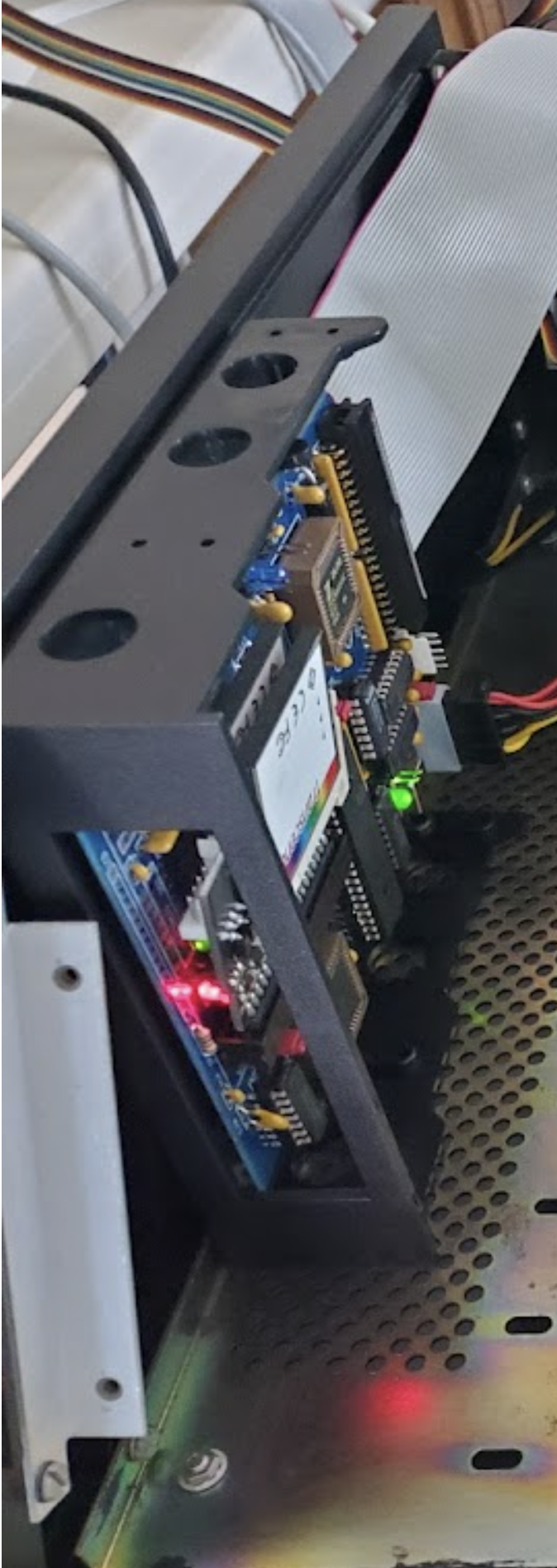
Well that worked! Here’s the system in an actual chassis (nothing permanently mounted yet)
https://photos.app.goo.gl/tjVbsK4mJyB6SSQ17
it boots!
https://photos.app.goo.gl/8DBhj7bxvCKVZLjx7
I will soon work on fitting things in permanently to the chassis. Will probably mount the Z67IDE+ like I did the one in Rusty:
To view this discussion on the web visit https://groups.google.com/d/msgid/sebhc/13f63c93-57a6-44e1-a627-6d23b299fd76n%40googlegroups.com.
norberto...@koyado.com
I will fix this for the production board. I had same issue in removing such part.
Thanks,
Norberto
To view this discussion on the web visit https://groups.google.com/d/msgid/sebhc/02ba01d7a17c%24d7c72c10%2487558430%24%40gmail.com.
norberto...@koyado.com
Glad that everything is working out for a an H8 running without the front panel.
On the jumpers to break out the H8 backplane, I will start a pcb board to do this as there are a lot of jumpers to insert.
Thanks,
Norberto
To view this discussion on the web visit https://groups.google.com/d/msgid/sebhc/031c01d7a1ad%24b3089fe0%241919dfa0%24%40gmail.com.
Norberto Collado
Hello Glenn,
After seen the Z67-IDE+ inside your new H8 chassis, it just gave me the idea of building a simple bracket to do the same using the H8 chassis holes to hold it in place. This gives us more space as your current solution is taking space. Here is our first draft and will send you one once we polish it a little more. Also you can paint it in black or any other color.
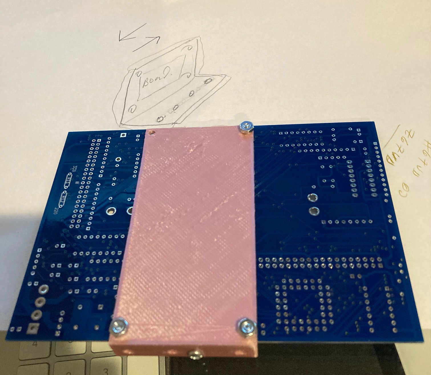
To view this discussion on the web visit https://groups.google.com/d/msgid/sebhc/031c01d7a1ad%24b3089fe0%241919dfa0%24%40gmail.com.
glenn.f...@gmail.com
Yes. What I did on Rusty was re-purpose and cut down a standard 3.5” to 5.25” disk drive converter
https://photos.app.goo.gl/rnx6PEvXTYc6Qxqz7
but a custom 3D-printed bracket would be a great solution!
When I eventually have wooden side panels I’d like to insert some of the 6-32 brass fittings into the wood so that I can mount standoffs and attach directly to the side..
To view this discussion on the web visit https://groups.google.com/d/msgid/sebhc/B5D569FC-C894-4C24-9738-FBAB6DEE67F4%40koyado.com.
Norberto Collado
Adding the fittings into the wood will be ideal. I’m building the 3D print to add the controller inside the H8 as now I have more space.
Norberto
To view this discussion on the web visit https://groups.google.com/d/msgid/sebhc/002701d7a23e%24771d25f0%24655771d0%24%40gmail.com.
Norberto Collado
Here is the final solution. The holes aligned nicely with the H8 chassis to secure it properly.

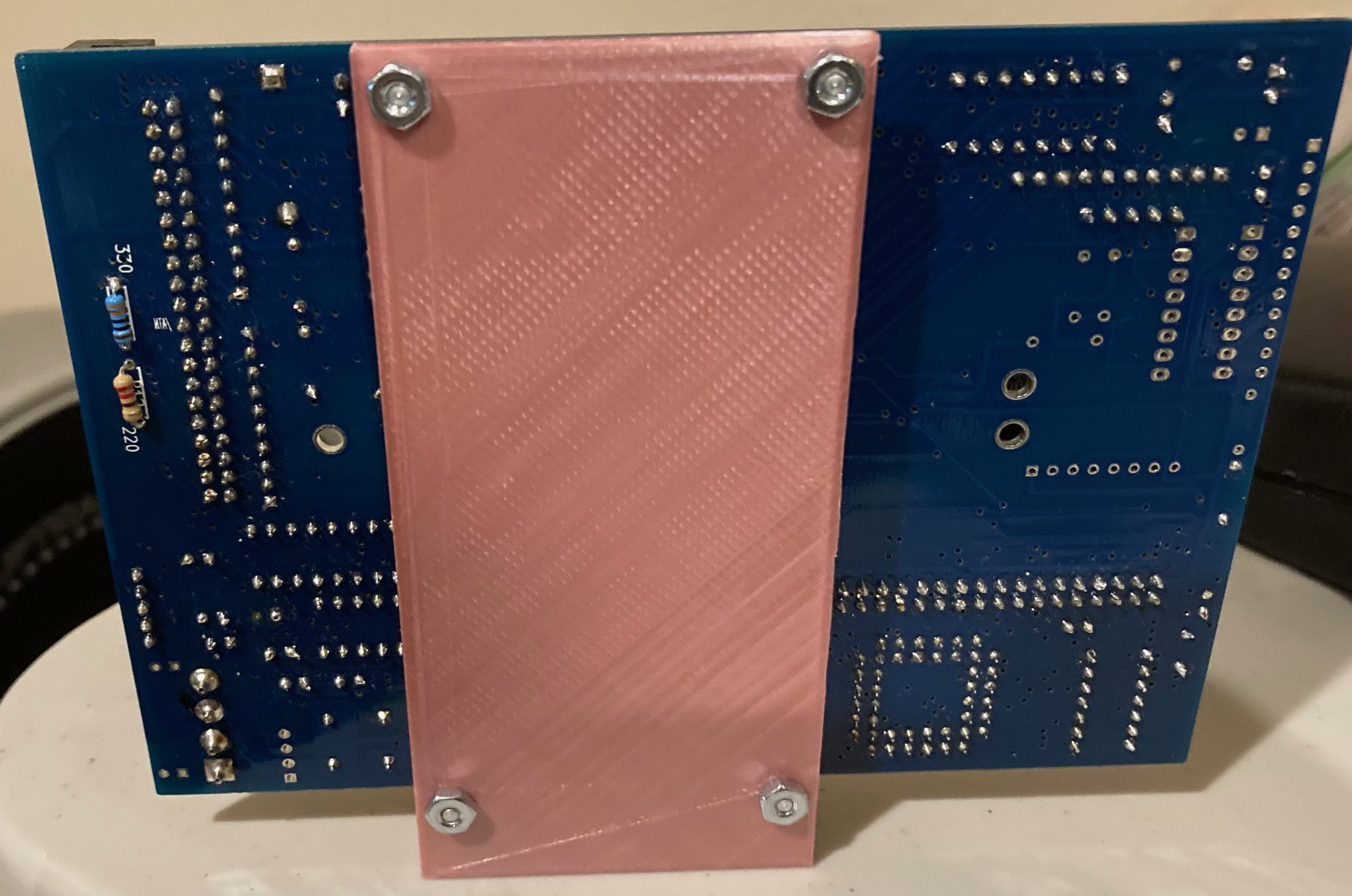
Norberto
To view this discussion on the web visit https://groups.google.com/d/msgid/sebhc/002701d7a23e%24771d25f0%24655771d0%24%40gmail.com.
Glenn Roberts
On Sep 6, 2021, at 1:30 AM, Norberto Collado <norberto...@koyado.com> wrote:
Here is the final solution. The holes aligned nicely with the H8 chassis to secure it properly.
<image001.jpg>
<image002.jpg>
Norberto
From: "se...@googlegroups.com" <se...@googlegroups.com> on behalf of <glenn.f...@gmail.com>
Reply-To: "se...@googlegroups.com" <se...@googlegroups.com>
Date: Sunday, September 5, 2021 at 3:11 AM
To: "se...@googlegroups.com" <se...@googlegroups.com>
Subject: RE: [sebhc] H8-2020
Yes. What I did on Rusty was re-purpose and cut down a standard 3.5” to 5.25” disk drive converter
https://photos.app.goo.gl/rnx6PEvXTYc6Qxqz7
but a custom 3D-printed bracket would be a great solution!
When I eventually have wooden side panels I’d like to insert some of the 6-32 brass fittings into the wood so that I can mount standoffs and attach directly to the side..
From: se...@googlegroups.com <se...@googlegroups.com> On Behalf Of Norberto Collado
Sent: Sunday, September 05, 2021 1:06 AM
To: se...@googlegroups.com
Subject: Re: [sebhc] H8-2020
Hello Glenn,
After seen the Z67-IDE+ inside your new H8 chassis, it just gave me the idea of building a simple bracket to do the same using the H8 chassis holes to hold it in place. This gives us more space as your current solution is taking space. Here is our first draft and will send you one once we polish it a little more. Also you can paint it in black or any other color.
<image003.jpg>
<image004.png>
To view this discussion on the web visit https://groups.google.com/d/msgid/sebhc/81840FAB-357F-49D5-ACE2-E0C9F092D3EC%40koyado.com.
Norberto Collado
I will ship 2-pcs to you and will post the 3D model on the web site.
To view this discussion on the web visit https://groups.google.com/d/msgid/sebhc/C8864BA0-F790-4290-B3BF-88AA1BBAC36C%40gmail.com.
Norberto Collado
3D prints here:
http://koyado.com/heathkit/New-H8-Website/h8-backplane.html
Z67-IDE+ bracket
http://koyado.com/heathkit/New-H8-Website/download/pcb-plate.stl.zip
H8 I/O Panel
http://koyado.com/heathkit/New-H8-Website/download/port-panel.stl.zip
Norby