HA-8-3-1 (Atari) Joystick interface..

57 views
Skip to first unread message

Joe Travis N6YPC

unread,
Nov 27, 2022, 4:50:53 PM11/27/22
to SEBHC
Greetings All,

I searched the archives here and Norberto's webpage for the HA-8-3-1 but didn't find an answer to my question:  Is there a connection diagram / guide for using Atari style joysticks with the HA-8-3-1?

I found the info on interfacing analog paddles / joysticks and am a  little surprised in not finding anything for the digital variety.

Thanks,
Joe Travis n6ypc

Glenn Roberts

unread,
Nov 27, 2022, 5:08:45 PM11/27/22
to se...@googlegroups.com
These use 5 switches (left, right, up, down, and trigger) but the HA8-3 has only one 8-bit parallel port to service all joysticks. Terry Smedley has an approach using voltage divider resistors to use the A to D converter. This has the advantage of being compatible with a potentiometer-based joystick. If you don't need the trigger button and need only two sticks then it’s straightforward. Could also use the ADC to read the trigger…

Sent from my iPad

On Nov 27, 2022, at 4:50 PM, Joe Travis N6YPC <jtravi...@gmail.com> wrote:

Greetings All,
--
You received this message because you are subscribed to the Google Groups "SEBHC" group.
To unsubscribe from this group and stop receiving emails from it, send an email to sebhc+un...@googlegroups.com.
To view this discussion on the web visit https://groups.google.com/d/msgid/sebhc/1f8c5eda-d2df-4ecb-bbd1-eee81cc3a874n%40googlegroups.com.

Joseph Travis

unread,
Nov 27, 2022, 6:03:22 PM11/27/22
to se...@googlegroups.com
The schematics show two 8 bit ports being used to service 4 joystick ports.  The unfortunate thing is instead of dividing two 8 bit ports into four 4 bit ports, they use 2 bits from each 8 bit port for each of the 4 ports.  The hassle there being it requires 2 I/O port reads for one joystick.

4 bits is sufficient for using an Atari style joystick.  One bit each for UP, DOWN, LEFT, RIGHT and the "fire" button(s) are handled by using 2 diodes connected between the button and two opposite directions (UP-DOWN or LEFT-RIGHT) so that both are low when the button is pressed.  This gives you 10 different combinations plus NOTHING (total of 11).

Joe


Glenn Roberts

unread,
Nov 27, 2022, 6:22:35 PM11/27/22
to <sebhc@googlegroups.com>
Sounds great. I don't have schematics so my bad for not remembering. I don't think a standard way to do this has been written up so you get to define it!

Les Bird

unread,
Dec 8, 2022, 8:42:02 PM12/8/22
to SEBHC
Joe, you built the HA-8-3-1 yourself? Any gotchas? I'm almost finished building mine, a few more chips coming tomorrow to finish it. I constructed a audio/video cable according to documentation - I used the pre-made RCA cables (got from Amazon) and cut them in half like Terry S suggested. How did you make your audio/video cable?

Les

Les Bird

unread,
Dec 8, 2022, 8:46:18 PM12/8/22
to SEBHC
IMG_1828.JPG

Joseph Travis

unread,
Dec 8, 2022, 10:11:32 PM12/8/22
to se...@googlegroups.com
Hi Les,

The only gotchas I had was due to my familiarity with the original HA-8-3 and the differences with the new version.

I wanted to use the cables from my original HA-8-3 but the connectors / pinouts are different so I used a HDMI breakout cable and cut off the damaged HDMI connector.  The other end had RCA phono plugs.  I chose to use the TMS-9918 (vice the TMS-9928) so I could use the NEC color monitor that I've kept for almost 40 years!

As you may have read in this thread, the joystick connectors are different too.  I've got a box full of Atari (digital) style joysticks and plan to use those instead of the Kraft (analog) style for any software I develop.  I also have a pair of Atari (analog) paddles and a Koala Pad which I can use.  All I need is time!  :)

Best Regards,
Joe

You received this message because you are subscribed to a topic in the Google Groups "SEBHC" group.
To unsubscribe from this topic, visit https://groups.google.com/d/topic/sebhc/rM8umClZBdk/unsubscribe.
To unsubscribe from this group and all its topics, send an email to sebhc+un...@googlegroups.com.
To view this discussion on the web visit https://groups.google.com/d/msgid/sebhc/683b0402-11a8-41d2-8319-22d4086bd343n%40googlegroups.com.

Les Bird

unread,
Dec 8, 2022, 10:40:54 PM12/8/22
to SEBHC
Great! Yes, the lack of compatibility with the older cables and hardware is a gotcha.

As a follow up question, do you have a V3 or 4 CPU card? I'm trying to configure the card for a V2 CPU but I'm super confused about all the wait state jumpers (amongst others) and how they should be set up for a V2 card. I'll need to read the documentation (again) to better understand this.

I suspect my first attempt tomorrow when I get the remaining chips will be unsuccessful and I'll need more time to configure it properly.

I have a TV with component inputs so will be using the 9928.

We really should spec out and standardize a universal controller that EVERYONE with a HA-8-3 (old and new) should use going forward. It would make writing software for these cards much easier.

Les

norberto.collado koyado.com

unread,
Dec 8, 2022, 11:20:15 PM12/8/22
to se...@googlegroups.com

Yes, the lack of compatibility with the older cables and hardware is a gotcha.


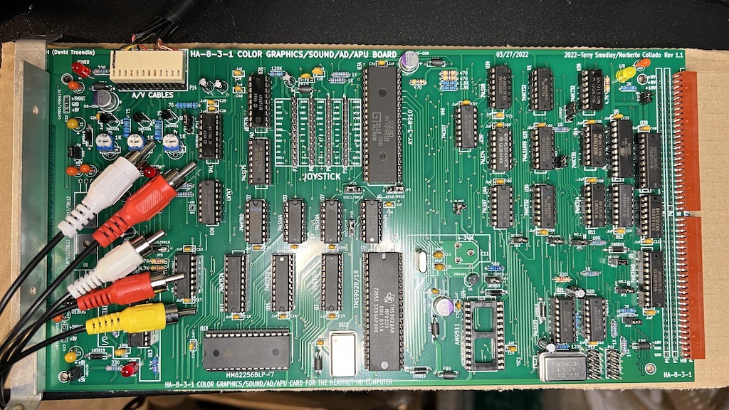
I do not understand this. Can you elaborate? On the picture below I only see two 3-pin connectors which did get combine into a 12 pin connector to give you more options (analog ground & digital ground).


The 10-pin connectors for the joysticks are the same, so you can use same cable. We expanded such connector to 12-pin to buffer some signals, so it can drive more current. I don’t get it!!!!!


Can you send me a picture of the original connector?


Diagram, schematic

Description automatically generated

Joseph Travis

unread,
Dec 8, 2022, 11:59:29 PM12/8/22
to se...@googlegroups.com
Both of my H8s have the 8080 CPU board although, the H8 with the HA-8-3-1 board uses a Pat Swayne Z80 adapter on the CPU board.

I believe Glenn may be of greater assistance in helping you with the required setup. Good luck!

BR,
Joe


Les Bird

unread,
Dec 9, 2022, 12:00:37 AM12/9/22
to SEBHC
Oh interesting. Maybe I missed something in the documentation that explained this...? It's certainly possible. I saw the connector footprints (audio/video/joysticks) and the diagram and they looked completely redesigned. I had no idea they would work with the old original cables. Thanks for clarifying. I see now that 3,4,5 are for composite video out (matching the original 3 pin configuration) and 10,11,12 are where the original 3 pin audio cable plugs in but I saw no mention of this in the documentation. The only thing I saw in the documentation was how to wire up a new 12 pin cable.

The other thing that threw me off was the section in the documentation about needing to re-assemble source code so that games and demos will work with the new joystick interface by changing the port assignments. Again, confusing and led me to believe that the joystick interface was different but really it's that they are at a different port number.

So another question, can we configure the board to look exactly like the original with the original ports? And if so, how can we do that? I saw a blurb about the ports being part of the GAL? Is that right? What would be helpful in the documentation is (1) example jumper configuration that sets the board up as the original for a V2 or earlier CPU board running at 2 MHz and (2) pics showing how to use the original cables.

Les


norberto.collado koyado.com

unread,
Dec 9, 2022, 12:29:20 AM12/9/22
to se...@googlegroups.com

can we configure the board to look exactly like the original with the original ports?


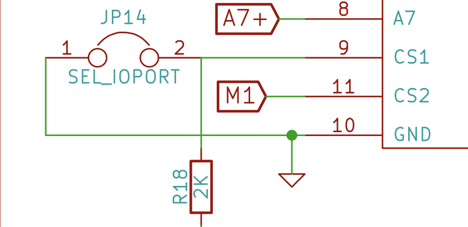
Yes, just change JP14. This jumper allows to use original ports or the new ports.


Timeline

Description automatically generated


needing to re-assemble source code so that games and demos will work with the new joystick interface by changing the port assignments


To use the new I/O ports, the code has been re-assembled. You can use original code on the original ports or the new ports on the re-assembled code. I tested this and it works fine.


The re-compiled code is here:Graphical user interface, text, application

Description automatically generated


the joystick interface was different


It is the same as the original design with the addition of pins to buffer some of the signals to drive an LED directly.


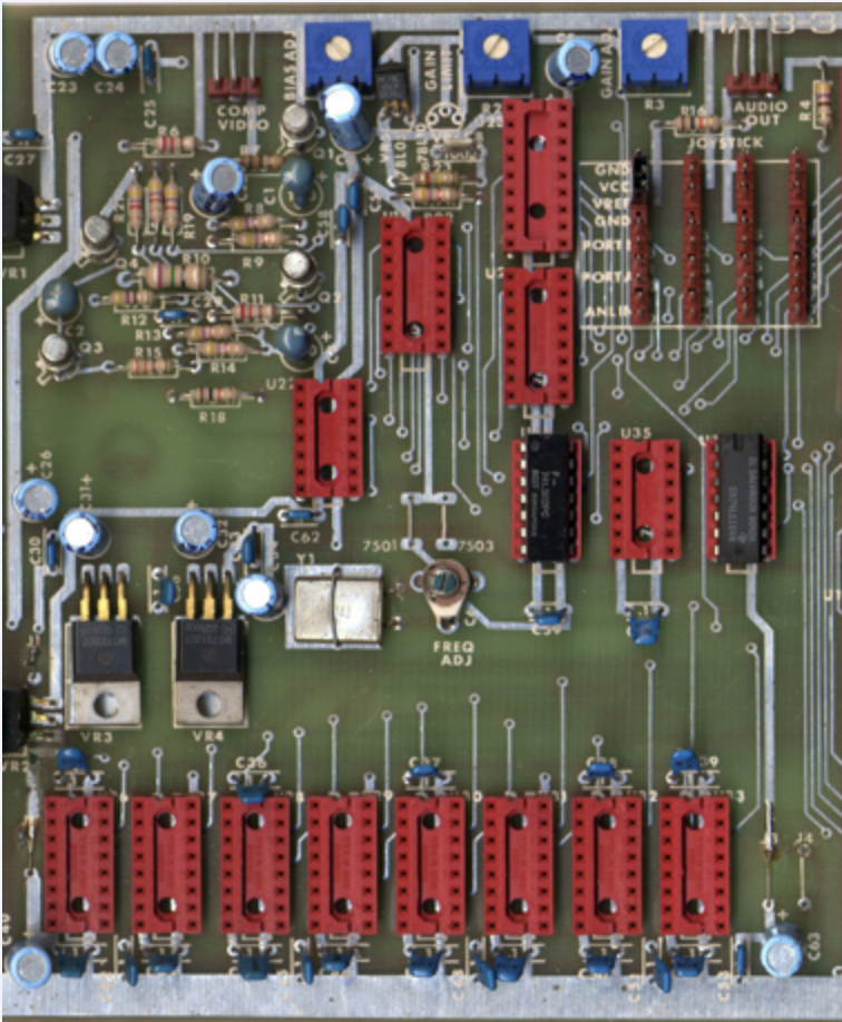
This design is the same as the original with enhancements to make it better. I assembled my board, put in the IC’s and it worked without any issues.


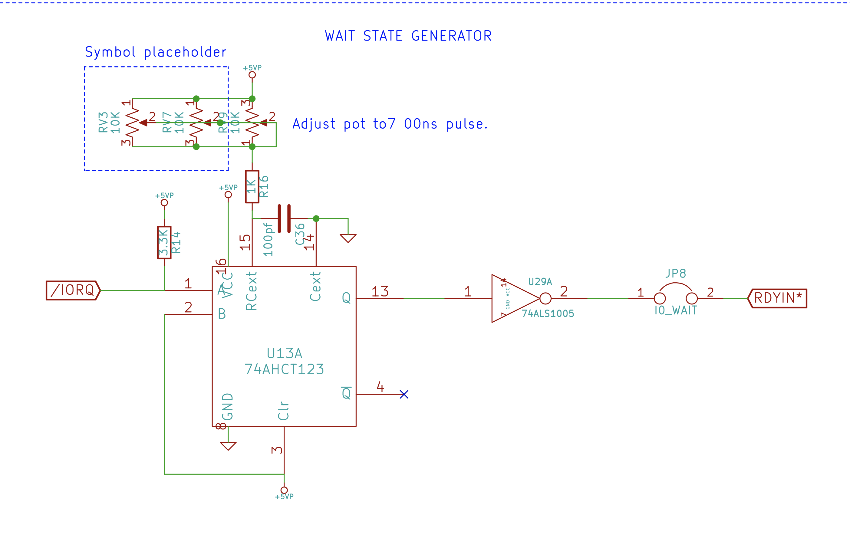
The wait state generator is optional if only running at max of 10MHz. If running above 10MHz, then you will need to use it. Just adjust the pot to 700ns pulse and that’s it. This feature is used when booting from the H8-67/ Z67-IDE+ controller.


You can use the wait state generator with the H17/H37 even at 2MHz. The system runs very smoothly. You can run the original H8-4 board at 10MHZ without any issues.


With the new Z180 it can go beyond 20MHz.


Diagram, schematic

Description automatically generated


Hope this helps,


Norberto

norberto.collado koyado.com

unread,
Dec 9, 2022, 12:33:30 AM12/9/22
to se...@googlegroups.com

Per documentation: JP14 ON (inserted) = original HA-8-3 addresses.


glenn.f...@gmail.com

unread,
Dec 9, 2022, 5:53:55 PM12/9/22
to se...@googlegroups.com

Catching up on last night's email discussion…


The reason for the alternate port capability is that the default port settings for the HA-8-3 create a conflict for users who have the H67 set at port 274Q.  this was an “unsupported” configuration for Heath but with Norberto’s 37/67 combo board it’s the only way to run H17, H37 and H67 units on the same box.

image001.png
image002.png
image003.png

Joe Travis N6YPC

unread,
Dec 29, 2022, 4:57:35 PM12/29/22
to SEBHC
Here is the scheme I came up with to use an Atari joystick, paddles or Koala Pad with the HA-8-3-1 board.  The diodes used are 1N4148/9 or similar small signal diodes.  Software would detect the button press by seeing both UP and DOWN at the same time.  An analog joystick wired to match the paddles would also work.

Unfortunately, I'm unable to fully test this at the moment as the AY-3-8910 I purchased on ebay (as part of a kit of IC's for the HA-8-3) is defective.  Both ports A and B are bad.  If someone has a reliable source for that IC, please let me know.  Thanks!

Joe

HA-8-3 Atari Joystick Interface.pdf

Glenn Roberts

unread,
Dec 29, 2022, 5:37:54 PM12/29/22
to se...@googlegroups.com
Joe: try

https://www.arcadepartsandrepair.com/store/pinball-kits-parts/pinball-parts/ay-3-8910/

Sent from my iPad

On Dec 29, 2022, at 4:57 PM, Joe Travis N6YPC <jtravi...@gmail.com> wrote:

Here is the scheme I came up with to use an Atari joystick, paddles or Koala Pad with the HA-8-3-1 board.  The diodes used are 1N4148/9 or similar small signal diodes.  Software would detect the button press by seeing both UP and DOWN at the same time.  An analog joystick wired to match the paddles would also work.
HA-8-3 Atari Joystick Interface.pdf

Joseph Travis

unread,
Dec 29, 2022, 6:06:06 PM12/29/22
to se...@googlegroups.com
Thank you Glenn, I'll try them!

BTW - I forgot to mention, it's best to mount the diodes on the DB-9 connector.


--
You received this message because you are subscribed to the Google Groups "SEBHC" group.
To unsubscribe from this group and stop receiving emails from it, send an email to sebhc+un...@googlegroups.com.
Reply all
Reply to author
Forward
0 new messages