H8 Tear down to check the new backplane.

Norberto Collado
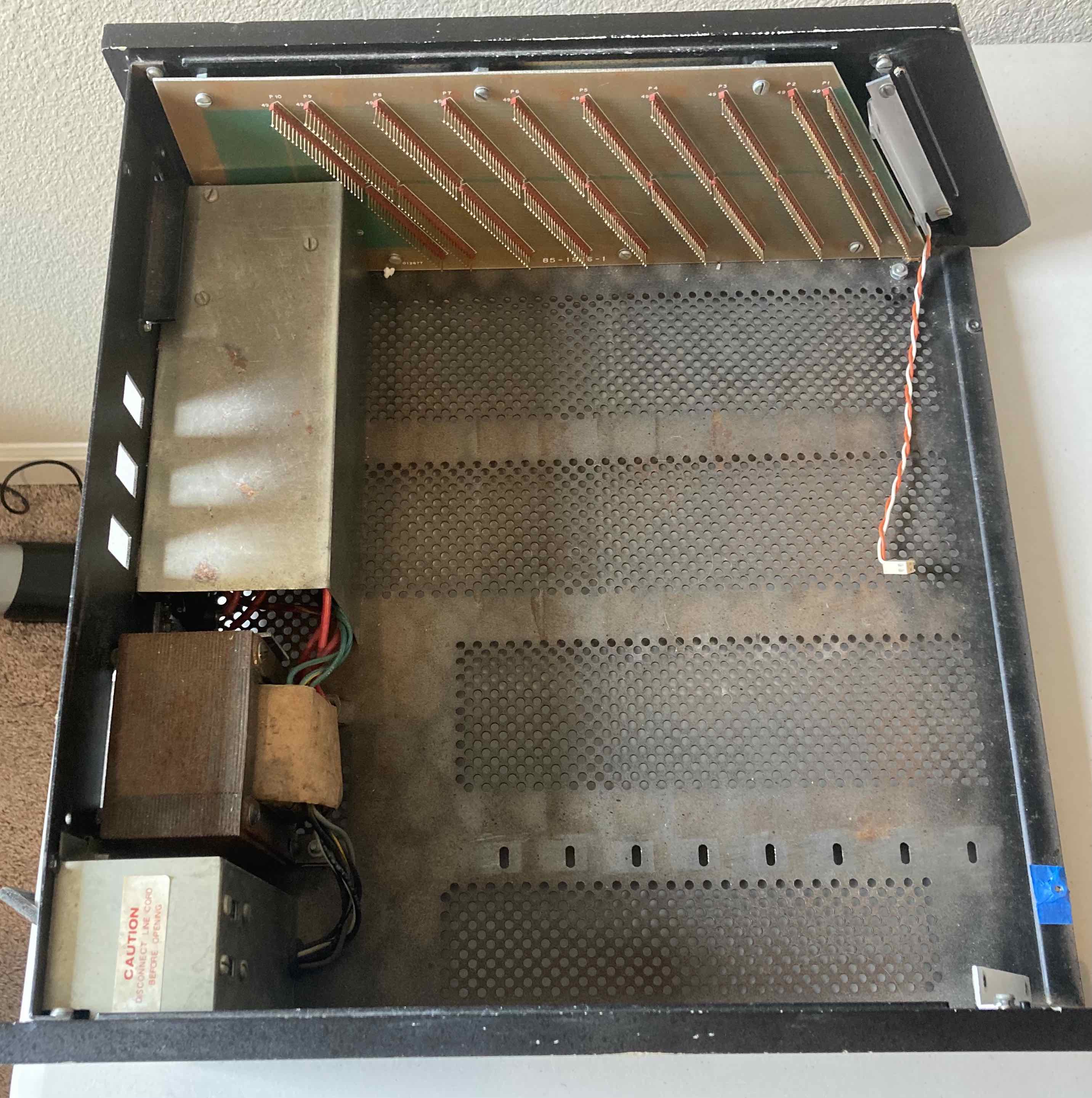
Here are some pictures on the H8 chassis tear down process and to check the hole alignment to install the BP screws.
There is rust inside the chassis. What chemical I can use to remove the rust before re-painting the inside of the chassis for better protection?
Tear down:
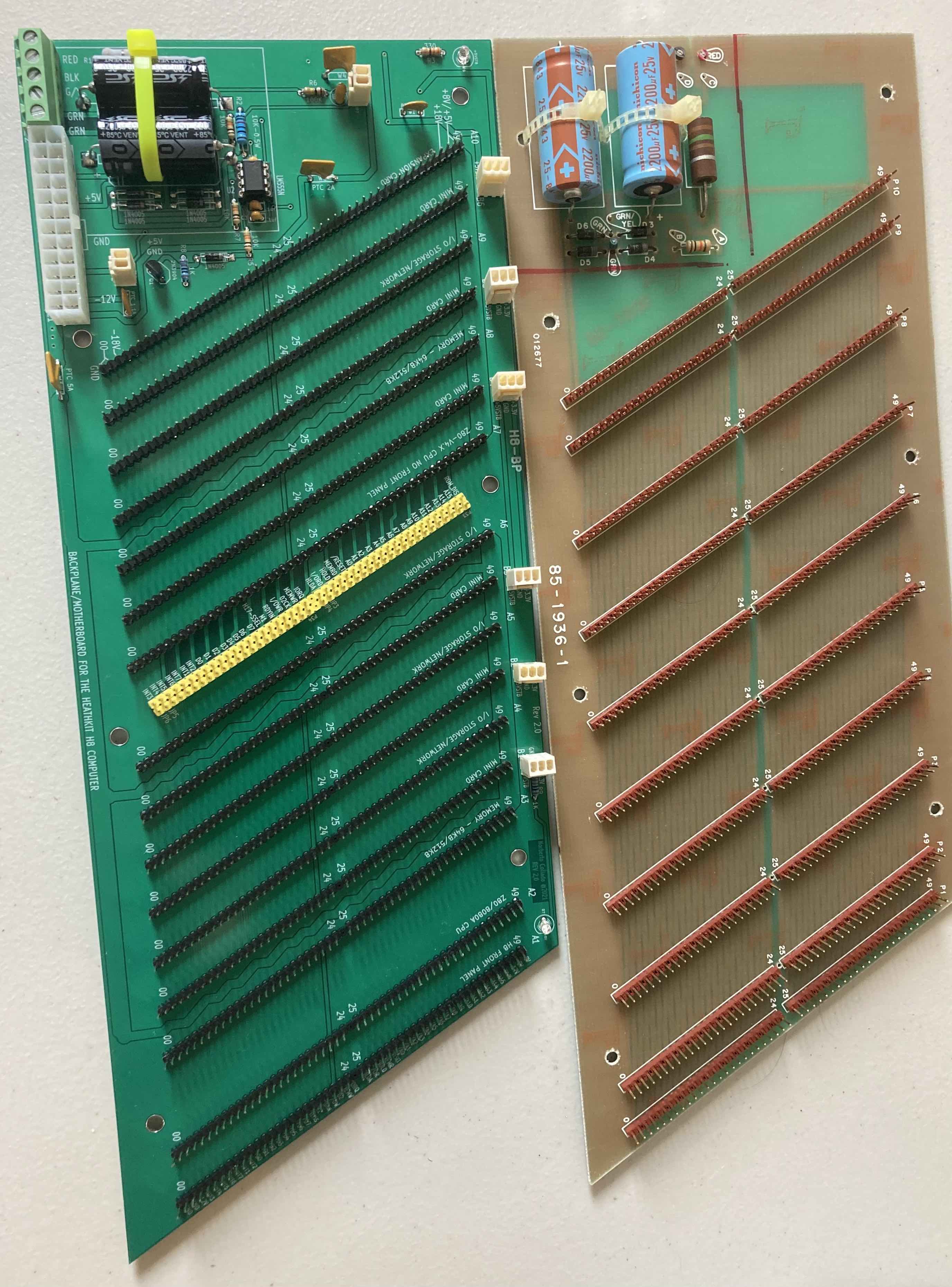
New H8 backplane smaller than the old one??? Will it fit?
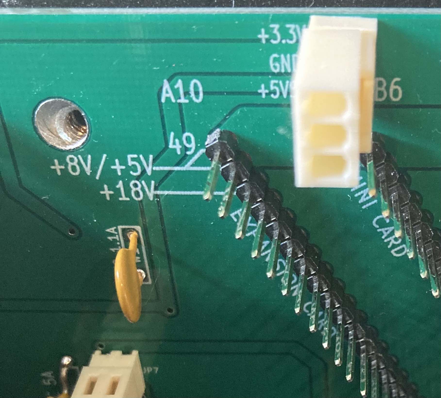
New H8 Backplane installed: No shorts from +8V to ground after installing screws.
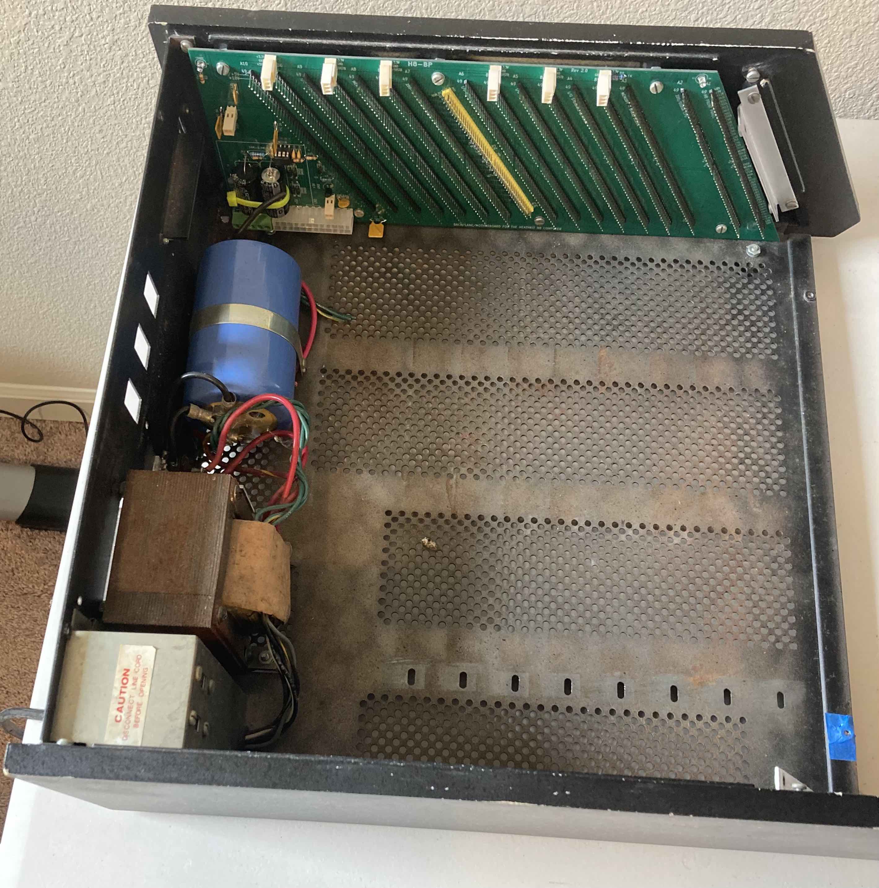
Only one hole off, but still can install the screw. I just found out that the new H8 Backplane is longer than the original. Will fix for production.
Norberto
Norberto Collado
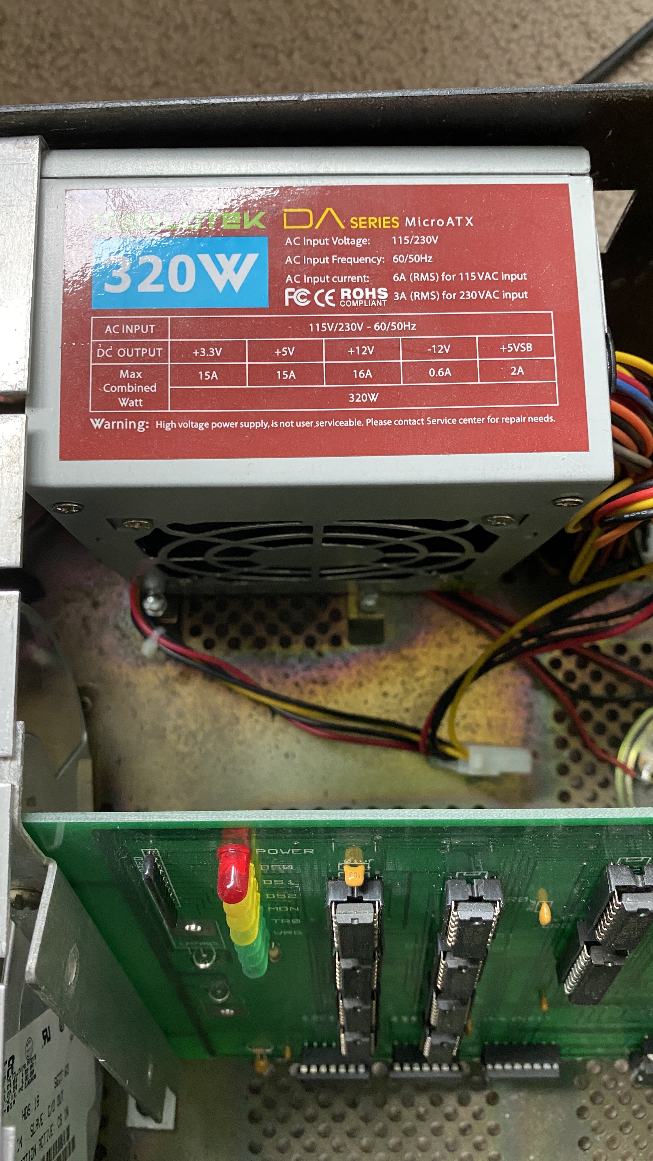
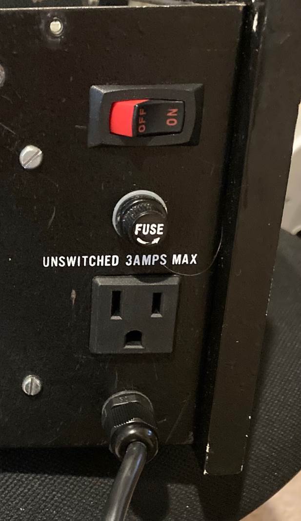
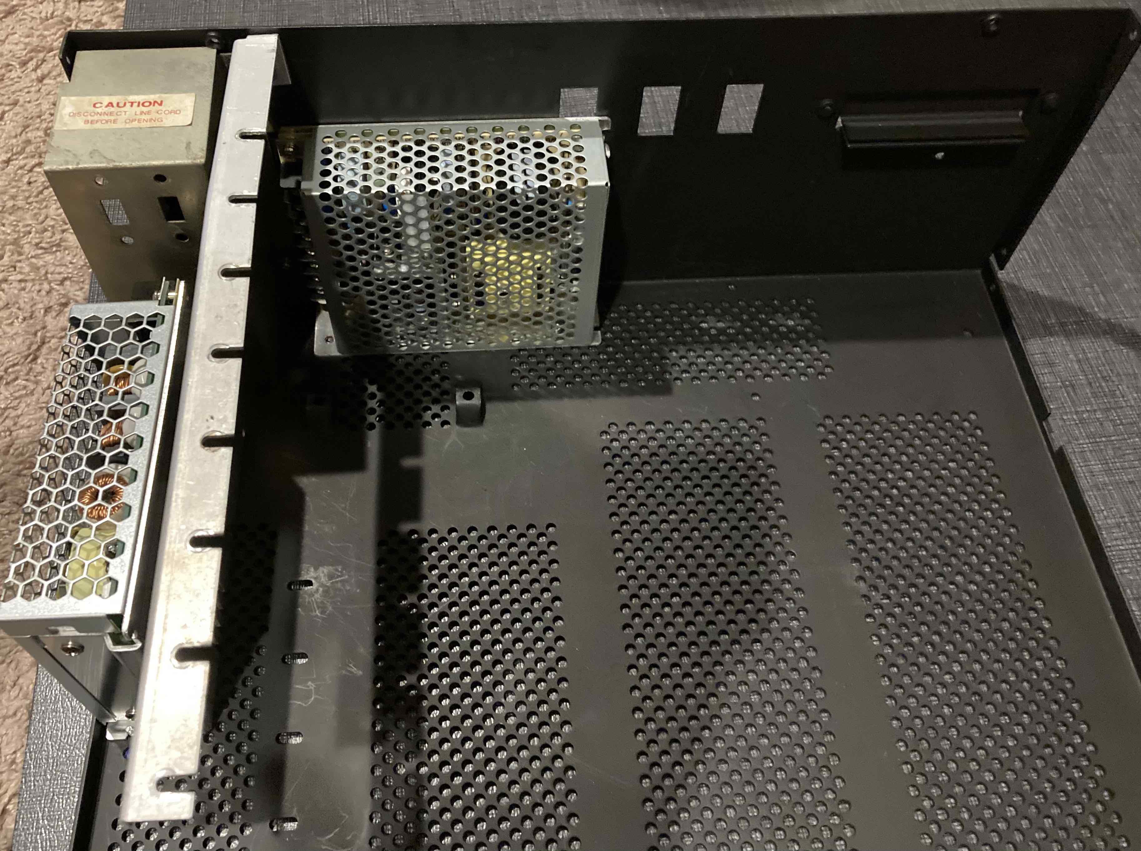
The ATX Mini Power Supply fits nicely and the fan covers the transformer hole. No need for a fan guard. This is the final solution and will re-attached the cover for the 110V AC to keep the inside of the H8 safe. I will keep using the original H8 ON/Off switch to control AC ON/OFF to the Power supply. Will replace the fuse with a momentary switch to control DC ON/OFF. I still need to figure out where to install another switch to be able to reset second CPU in dual configuration or perhaps use the SSI board to reset the second CPU board. Any feedback appreciated.
Now we have more space on the back of the H8 chassis for future expansion and the H8 chassis is not that heavy as before due to the weight of the transformer.
Norberto

Glenn Roberts
On Jul 31, 2021, at 8:25 PM, Norberto Collado <norberto...@koyado.com> wrote:
The ATX Mini Power Supply fits nicely and the fan covers the transformer hole. No need for a fan guard. This is the final solution and will re-attached the cover for the 110V AC to keep the inside of the H8 safe. I will keep using the original H8 ON/Off switch to control AC ON/OFF to the Power supply. Will replace the fuse with a momentary switch to control DC ON/OFF. I still need to figure out where to install another switch to be able to reset second CPU in dual configuration or perhaps use the SSI board to reset the second CPU board. Any feedback appreciated.
Now we have more space on the back of the H8 chassis for future expansion and the H8 chassis is not that heavy as before due to the weight of the transformer.
--
<image001.jpg>
Norberto
You received this message because you are subscribed to the Google Groups "SEBHC" group.
To unsubscribe from this group and stop receiving emails from it, send an email to sebhc+un...@googlegroups.com.
To view this discussion on the web visit https://groups.google.com/d/msgid/sebhc/DB593FAF-BB51-486B-AF0B-93683BB8CE71%40koyado.com.

Steven Feinsmith
Once you get oxidation or/and corrosive on the board. It was DONE! The only way to clone and make a modern type of PCB.
To view this discussion on the web visit https://groups.google.com/d/msgid/sebhc/642FDB92-CA95-4A4C-B4F1-2565ABD23C98%40gmail.com.

Mark Garlanger
To view this discussion on the web visit https://groups.google.com/d/msgid/sebhc/CAGJMgmVdCjG5%2B%3DEVBmM_gVqSPLrcd1Z%3Djrb2HvisiJk%3Dkt%3Dp6A%40mail.gmail.com.
glenn.f...@gmail.com
Correct. Thanks for clarifying Mark. I was responding to two emails at once (the other email Norberto sent asked how to remove rust from the metal chassis)…
- Glenn
To view this discussion on the web visit https://groups.google.com/d/msgid/sebhc/CAAjkm79O4TuugjMfnZdUhE4OROm-UXosxZ-aJvPXVudq1A4i7w%40mail.gmail.com.
Norberto Collado
Thanks and my way to the HW store to get the parts!
Norberto
From: "se...@googlegroups.com" <se...@googlegroups.com> on behalf of Glenn Roberts <glenn.f...@gmail.com>
Reply-To: "se...@googlegroups.com" <se...@googlegroups.com>
Date: Saturday, July 31, 2021 at 6:06 PM
To: "se...@googlegroups.com" <se...@googlegroups.com>
Subject: Re: [sebhc] H8 Tear down to check the new backplane.
This pretty much mirrors my experience building Rusty. It’s been my rock solid go to system all these years. Lightweight and cool running.
To view this discussion on the web visit https://groups.google.com/d/msgid/sebhc/642FDB92-CA95-4A4C-B4F1-2565ABD23C98%40gmail.com.

Les Bird
The ATX Mini Power Supply fits nicely and the fan covers the transformer hole. No need for a fan guard. This is the final solution and will re-attached the cover for the 110V AC to keep the inside of the H8 safe. I will keep using the original H8 ON/Off switch to control AC ON/OFF to the Power supply. Will replace the fuse with a momentary switch to control DC ON/OFF. I still need to figure out where to install another switch to be able to reset second CPU in dual configuration or perhaps use the SSI board to reset the second CPU board. Any feedback appreciated.
Now we have more space on the back of the H8 chassis for future expansion and the H8 chassis is not that heavy as before due to the weight of the transformer.

Norberto
Norberto Collado
Les,
Agreed and thank you for creating the “H8-H200” project, which has been the inspiration for the upgrades. That was a lot of work for you to do in such short time.
As the H8 chassis is all dis-assembled and my son is out of school, he decided to start building the H8 chassis using his CAD tools. In just a few hrs.’ he already completed the side panels. Tomorrow he will do the chassis and then he will add the provided feedback.
Here is what we did today:
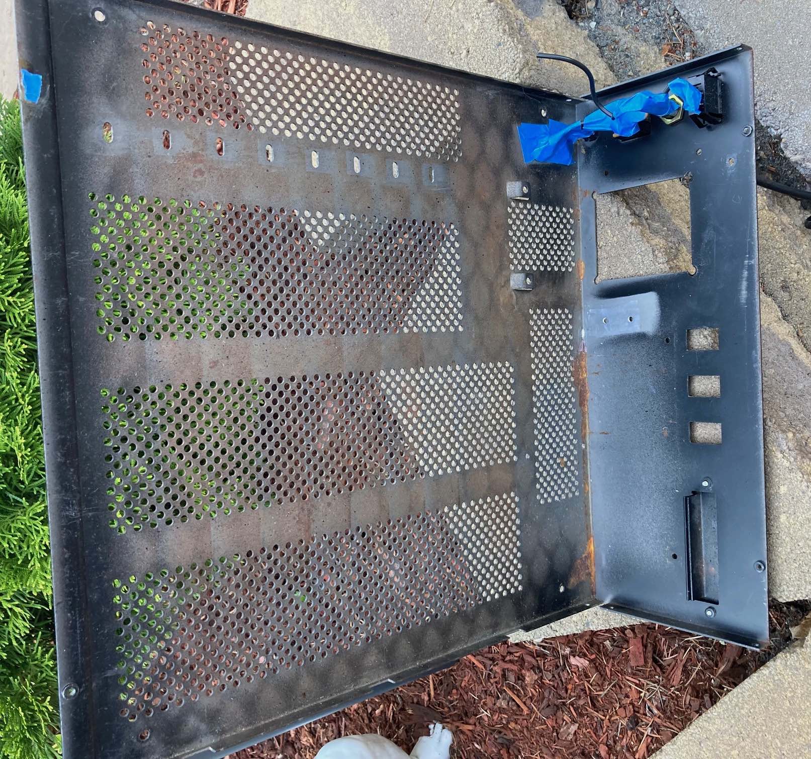
H8 Chassis with internal rust. I do not know why Heath did not paint the inside of the chassis to avoid such rust.
Tools to remove rust:

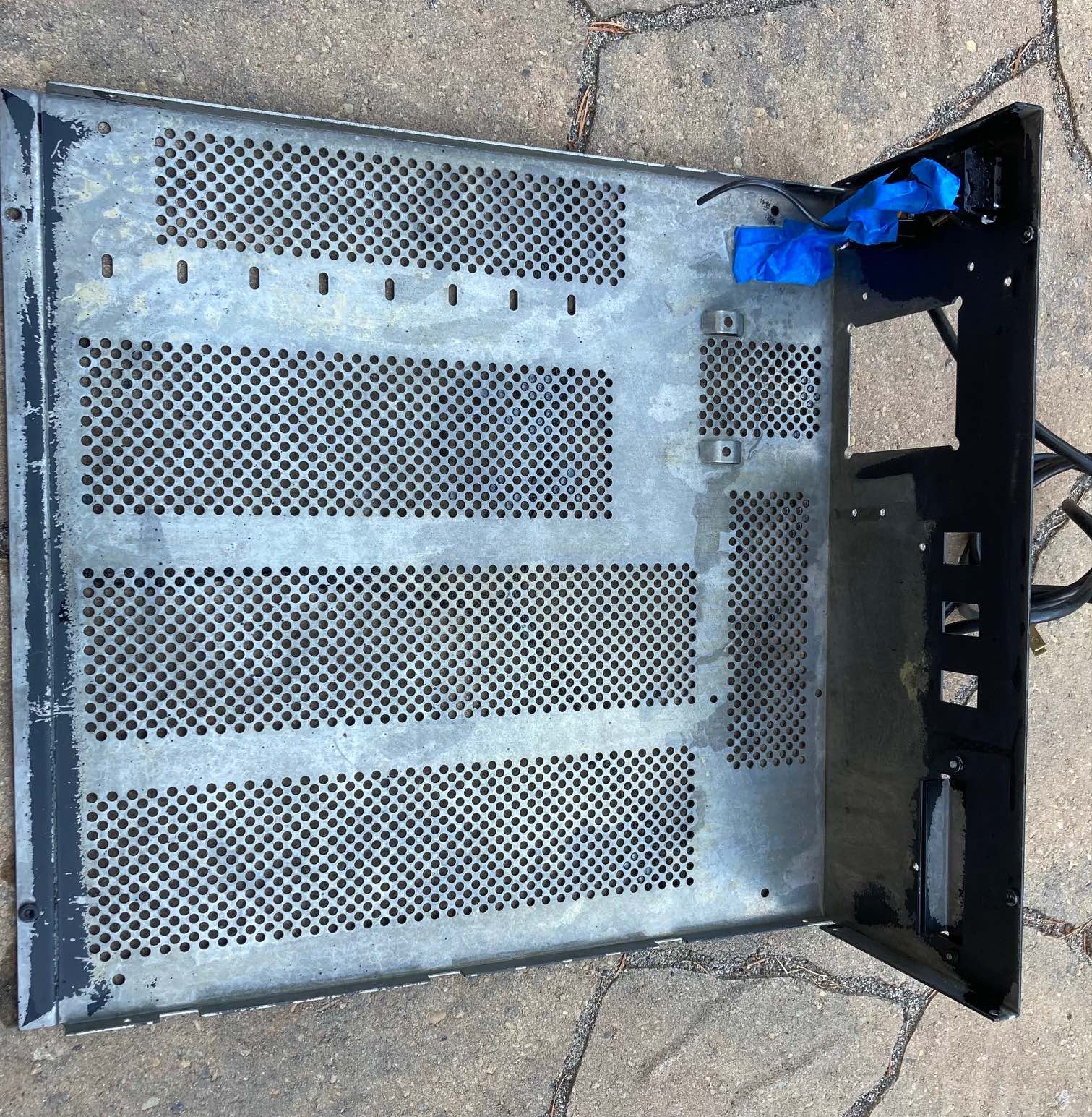
H8 Chassis – Rust removed:
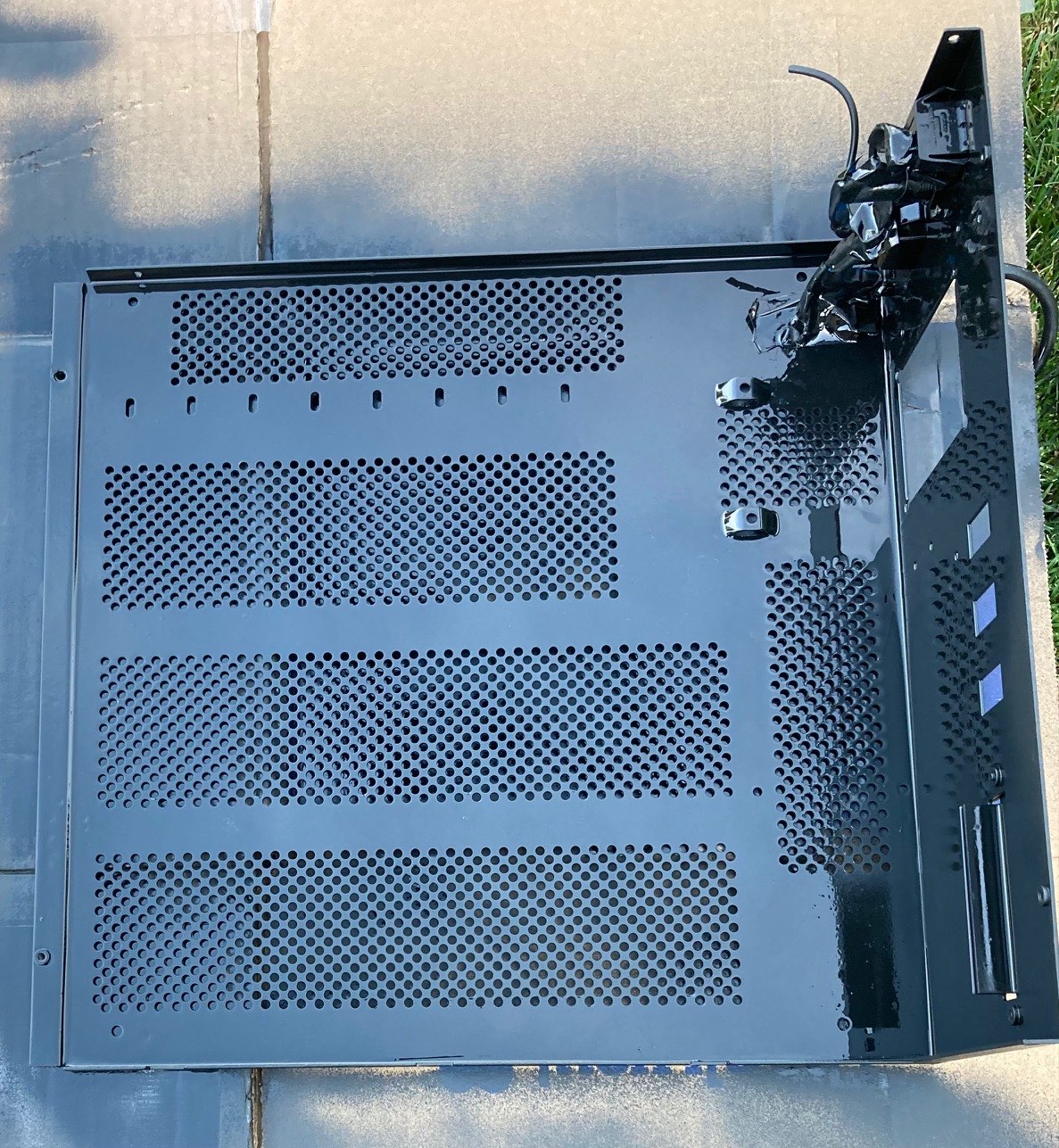
H8 Chassis Painted: I just painted the internal chassis. Did not paint the exterior.
New H8-Chassis in CAD: WIP
Norberto
From: "se...@googlegroups.com" <se...@googlegroups.com> on behalf of Les Bird <les...@bellsouth.net>
Reply-To: "se...@googlegroups.com" <se...@googlegroups.com>
Date: Sunday, August 1, 2021 at 6:39 PM
To: "se...@googlegroups.com" <se...@googlegroups.com>
Subject: Re: [sebhc] H8 Tear down to check the new backplane.
Glad to see my PC power supply feature for the motherboard is coming in handy and extending the life of the H8. New design looks good Norberto. And yes, amazing how much lighter the H8 is without the transformer.
Les
.
Steven Feinsmith
--
You received this message because you are subscribed to the Google Groups "SEBHC" group.
To unsubscribe from this group and stop receiving emails from it, send an email to sebhc+un...@googlegroups.com.
To view this discussion on the web visit https://groups.google.com/d/msgid/sebhc/834BB4B5-16E1-4355-A979-83C61F0D8461%40koyado.com.
Norberto Collado
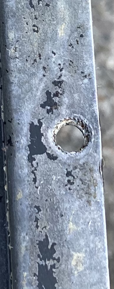
During the rust cleaning process the fastener that holds the screw for the front panel top cover came out. I’m guessing it was soldered by Heath supplier, but it came out. I think this was a defect by their supplier. What tool I need to fix this issue to be able to attached the front panel cover underneath screw? Is the same one used on the Heath card mount heatsink bracket, I think.
Issue:
Glenn Roberts
On Aug 2, 2021, at 12:10 AM, Norberto Collado <norberto...@koyado.com> wrote:
Les,
Agreed and thank you for creating the “H8-H200” project, which has been the inspiration for the upgrades. That was a lot of work for you to do in such short time.
As the H8 chassis is all dis-assembled and my son is out of school, he decided to start building the H8 chassis using his CAD tools. In just a few hrs.’ he already completed the side panels. Tomorrow he will do the chassis and then he will add the provided feedback.
Here is what we did today:
H8 Chassis with internal rust. I do not know why Heath did not paint the inside of the chassis to avoid such rust.
<image001.jpg>
Tools to remove rust:
<image002.jpg>
H8 Chassis – Rust removed:
<image003.jpg>
H8 Chassis Painted: I just painted the internal chassis. Did not paint the exterior.
<image004.jpg>
New H8-Chassis in CAD: WIP
<image005.jpg>
Norberto
From: "se...@googlegroups.com" <se...@googlegroups.com> on behalf of Les Bird <les...@bellsouth.net>
Reply-To: "se...@googlegroups.com" <se...@googlegroups.com>
Date: Sunday, August 1, 2021 at 6:39 PM
To: "se...@googlegroups.com" <se...@googlegroups.com>
Subject: Re: [sebhc] H8 Tear down to check the new backplane.
Glad to see my PC power supply feature for the motherboard is coming in handy and extending the life of the H8. New design looks good Norberto. And yes, amazing how much lighter the H8 is without the transformer.
Les
.
--
You received this message because you are subscribed to the Google Groups "SEBHC" group.
To unsubscribe from this group and stop receiving emails from it, send an email to sebhc+un...@googlegroups.com.
To view this discussion on the web visit https://groups.google.com/d/msgid/sebhc/834BB4B5-16E1-4355-A979-83C61F0D8461%40koyado.com.
<mime-attachment>
Glenn Roberts
On Aug 2, 2021, at 3:02 AM, Norberto Collado <norberto...@koyado.com> wrote:
During the rust cleaning process the fastener that holds the screw for the front panel top cover came out. I’m guessing it was soldered by Heath supplier, but it came out. I think this was a defect by their supplier. What tool I need to fix this issue to be able to attached the front panel cover underneath screw? Is the same one used on the Heath card mount heatsink bracket, I think.
Issue:
<image001.jpg>
<image002.jpg>
--
You received this message because you are subscribed to the Google Groups "SEBHC" group.
To unsubscribe from this group and stop receiving emails from it, send an email to sebhc+un...@googlegroups.com.
To view this discussion on the web visit https://groups.google.com/d/msgid/sebhc/163D2E56-813F-4E9D-B4F8-45DFCDC66666%40koyado.com.
Glenn Roberts
On Aug 2, 2021, at 6:19 AM, Glenn Roberts <glenn.f...@gmail.com> wrote:
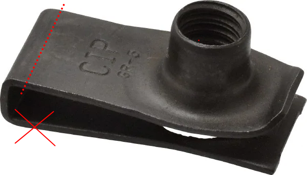
The part is called a self-clinching nut
norberto.collado koyado.com
Sent: Monday, August 2, 2021 4:56 AM
To: <se...@googlegroups.com> <se...@googlegroups.com>
Subject: Re: [sebhc] H8 Tear down to check the new backplane.
Steven Feinsmith
https://www.dontwasteyourmoney.com/best-rivet-nut-tool/
To view this discussion on the web visit https://groups.google.com/d/msgid/sebhc/SN6PR01MB3855DC81A843D16E17F975C6F7EF9%40SN6PR01MB3855.prod.exchangelabs.com.
norberto.collado koyado.com
Sent: Monday, August 2, 2021 11:58 AM
norberto.collado koyado.com
Glenn Roberts
--
You received this message because you are subscribed to the Google Groups "SEBHC" group.
To unsubscribe from this group and stop receiving emails from it, send an email to sebhc+un...@googlegroups.com.
To view this discussion on the web visit https://groups.google.com/d/msgid/sebhc/SN6PR01MB38559276137FA9EAE0125DC9F7F09%40SN6PR01MB3855.prod.exchangelabs.com.
norberto.collado koyado.com
To: <se...@googlegroups.com> <se...@googlegroups.com>
Subject: Re: [sebhc] H8 Tear down to check the new backplane.
Norberto Collado
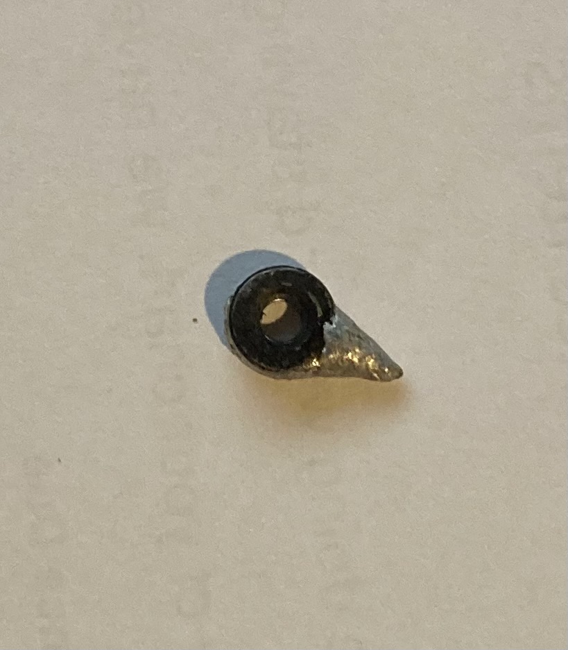
I received today the #6-32 self-clinch part and did try all possible methods to clinch the part into the metal. No matter how hard even hammering the part in, it does not want to go in. It requires a lot of force to clinch such part into the metal. I need a very powerful tool to do this as the case of the H8 is not aluminum and it is hard steel. Perhaps a HALF TON Power Press will do as this one.

I will clean up the hole with the steel tool and use Gorilla glue or epoxy to keep the part secure into the chassis. I think this should do it. Then repaint again.
Thanks for all the feedback.
Norberto
From: "norberto.collado koyado.com" <norberto...@koyado.com>
Date: Tuesday, August 3, 2021 at 11:39 AM
To: "se...@googlegroups.com" <se...@googlegroups.com>
Subject: Re: [sebhc] H8 Tear down to check the new backplane.
Good idea!
From: se...@googlegroups.com <se...@googlegroups.com> on behalf of Glenn Roberts <glenn.f...@gmail.com>
Sent: Tuesday, August 3, 2021 11:35 AM
To: <se...@googlegroups.com> <se...@googlegroups.com>
Subject: Re: [sebhc] H8 Tear down to check the new backplane.
You may have to reduce the diameter of the hole slightly to give the new nut sufficient purchase to hold. Perhaps tamp it a bit using a hammer and with something solid underneath to flatten out the sheet metal a bit around the hole.
.
Glenn Roberts
On Aug 5, 2021, at 1:27 AM, Norberto Collado <norberto...@koyado.com> wrote:
I received today the #6-32 self-clinch part and did try all possible methods to clinch the part into the metal. No matter how hard even hammering the part in, it does not want to go in. It requires a lot of force to clinch such part into the metal. I need a very powerful tool to do this as the case of the H8 is not aluminum and it is hard steel. Perhaps a HALF TON Power Press will do as this one.
<image001.jpg>
I will clean up the hole with the steel tool and use Gorilla glue or epoxy to keep the part secure into the chassis. I think this should do it. Then repaint again.
Thanks for all the feedback.
Norberto
From: "norberto.collado koyado.com" <norberto...@koyado.com>
Date: Tuesday, August 3, 2021 at 11:39 AM
To: "se...@googlegroups.com" <se...@googlegroups.com>
Subject: Re: [sebhc] H8 Tear down to check the new backplane.
Good idea!
From: se...@googlegroups.com <se...@googlegroups.com> on behalf of Glenn Roberts <glenn.f...@gmail.com>
Sent: Tuesday, August 3, 2021 11:35 AM
To: <se...@googlegroups.com> <se...@googlegroups.com>
Subject: Re: [sebhc] H8 Tear down to check the new backplane.
You may have to reduce the diameter of the hole slightly to give the new nut sufficient purchase to hold. Perhaps tamp it a bit using a hammer and with something solid underneath to flatten out the sheet metal a bit around the hole.
.
--
You received this message because you are subscribed to the Google Groups "SEBHC" group.
To unsubscribe from this group and stop receiving emails from it, send an email to sebhc+un...@googlegroups.com.
To view this discussion on the web visit https://groups.google.com/d/msgid/sebhc/79F1CACB-6C90-40FB-A170-52E1FC43E764%40koyado.com.

Paul Birkel
FWIW, if a filleted epoxy of the current threaded part into place doesn’t hold then you might consider getting a J-style clip-on nut and trimming off the back-end of the J – leaving two tabs that ought to give you better adhesion and control. Something like this:
To view this discussion on the web visit https://groups.google.com/d/msgid/sebhc/7596626F-251B-46CD-B183-32F7E6F8CB52%40gmail.com.

geneb
>> On Aug 5, 2021, at 1:27 AM, Norberto Collado <norberto...@koyado.com> wrote:
>>
>> I received today the #6-32 self-clinch part and did try all possible
>> methods to clinch the part into the metal. No matter how hard even
>> hammering the part in, it does not want to go in. It requires a lot of
>> force to clinch such part into the metal. I need a very powerful tool
>> to do this as the case of the H8 is not aluminum and it is hard steel.
>> Perhaps a HALF TON Power Press will do as this one.
g.
--
Proud owner of F-15C 80-0007
http://www.f15sim.com - The only one of its kind.
http://www.diy-cockpits.org/coll - Go Collimated or Go Home.
Some people collect things for a hobby. Geeks collect hobbies.
ScarletDME - The red hot Data Management Environment
A Multi-Value database for the masses, not the classes.
http://scarlet.deltasoft.com - Get it _today_!

John Evans
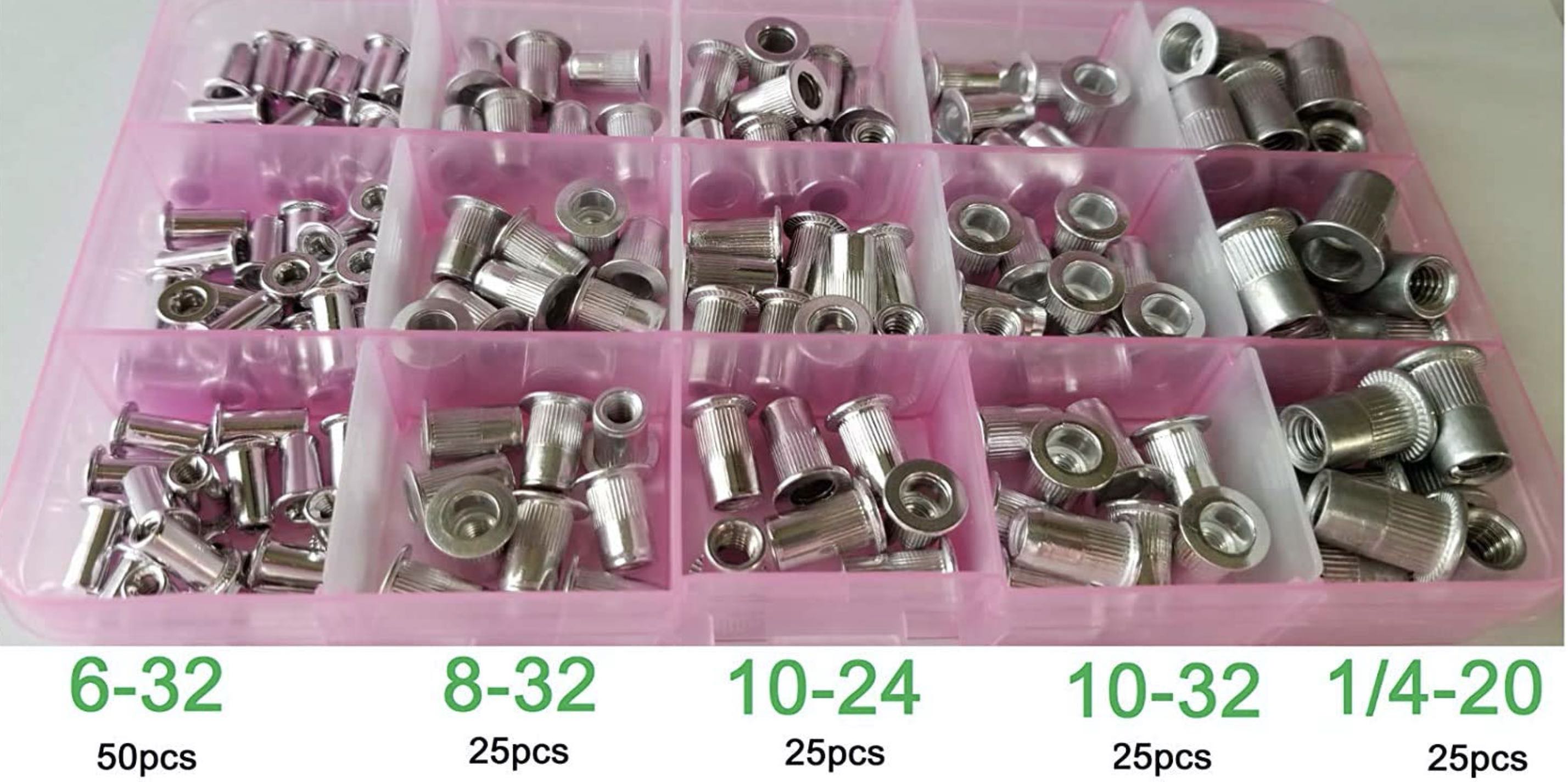
or a slightly enlarged hole. They work like pop-rivets to install.
https://www.rivetnutusa.com/rivnut-rivet-nut/
John - Colorado Springs
norberto.collado koyado.com
Sent: Thursday, August 5, 2021 6:29 AM
To: se...@googlegroups.com <se...@googlegroups.com>
Subject: Re: [sebhc] H8 Tear down to check the new backplane.
You received this message because you are subscribed to the Google Groups "SEBHC" group.
To unsubscribe from this group and stop receiving emails from it, send an email to sebhc+un...@googlegroups.com.
norberto.collado koyado.com
Sent: Thursday, August 5, 2021 3:22 AM
To: se...@googlegroups.com <se...@googlegroups.com>
Subject: RE: [sebhc] H8 Tear down to check the new backplane.
Steven Feinsmith
To view this discussion on the web visit https://groups.google.com/d/msgid/sebhc/SN6PR01MB3855F298E8714CC70FC2AC92F7F29%40SN6PR01MB3855.prod.exchangelabs.com.
norberto.collado koyado.com
Sent: Thursday, August 5, 2021 11:28 AM
Steven Feinsmith
To view this discussion on the web visit https://groups.google.com/d/msgid/sebhc/SN6PR01MB3855D2905B5BB96CE6BA2987F7F29%40SN6PR01MB3855.prod.exchangelabs.com.

G. Beat
Norberto Collado
My son gave me a preview of the original H8 chassis in CAD today. He shall be done tomorrow. Then he will work on the front panel cover and finally the H8 LED’s cover. He will assembled all the parts in CAD to make sure all holes do align properly. Once he is done, we will make a copy to build out the new H8 chassis using all new components and add the feedback received. At least we will have the original H8 design in CAD.
Attached is a picture rear sided view.
Thanks,
Norberto
norberto.collado koyado.com
Steven Feinsmith
My question is if we are seeking reproduction of the H8 chassis. Do we need to have an open hole for the transformer? We are no longer using the transformer and large capacitors (linear power supply). We use a switching power supply from Meanwell or PC PSU. We can adjust to a minimum voltage level to run in-board voltage regulators or choose a PC PSU and bypass the voltage regulators. Do we need airflow holes on the bottom and top cover? Should we allow open holes on sides for cooling fans with filters to bring forceful airflow to keep components cool as possible?
In case, we use a linear power supply. It is possible to have a company reproduce the transformer (custom-build). My major concern is electrolytic capacitors nowadays because the ripple current was higher during the old days.
Open to the discussion?
Thank you very much,
Steven
--
You received this message because you are subscribed to the Google Groups "SEBHC" group.
To unsubscribe from this group and stop receiving emails from it, send an email to sebhc+un...@googlegroups.com.
To view this discussion on the web visit https://groups.google.com/d/msgid/sebhc/SN6PR01MB385563711EB39AEA6509BC19F7F49%40SN6PR01MB3855.prod.exchangelabs.com.
Glenn Roberts
On Aug 6, 2021, at 9:47 PM, Steven Feinsmith <steven.f...@gmail.com> wrote:
To view this discussion on the web visit https://groups.google.com/d/msgid/sebhc/CAGJMgmWkfm_8JCHxBRfnRTgDsEnVWhcWF7ZsTRZxZ%2B5HRh5ibA%40mail.gmail.com.
Norberto Collado
I see two steps here:
- Reproduction of the original H8 chassis to preserved for history. If someone wants to duplicate the original chassis it can be done.
- Use the CAD files in step #1 to build the new H8 chassis. There is another email thread in which a lot of feedback was provided on what we need on this new chassis. In this re-design we add the ATX PSU/Mean Well PSU, RS232 holes, etc. I can expand later when we get to step 2.
- Per feedback from Glenn, the ATX PSU has its own fan and that is enough to cool the chassis. If I see space left in the back to put a small fan, I will do so. The new backplane support the +12V/+5V fans using same 4-pin header as in the PC.
Thanks,
Norberto
norberto.collado koyado.com
Norberto Collado
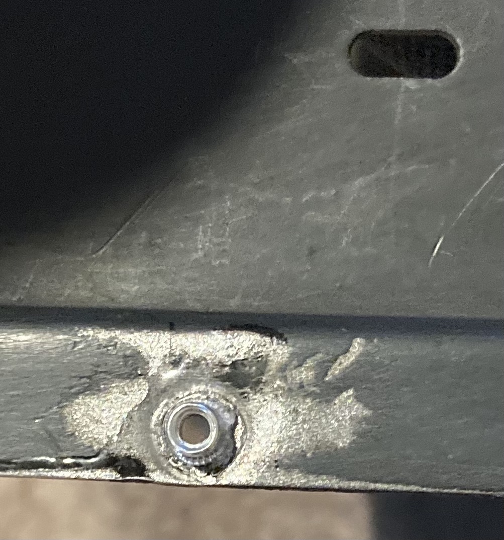
The rivenut #6-32 worked out fine. Easy to install with the right tools. Not as beautiful as using a clinch nut. To use the clinch nut again, the hole needs to be welded, smoothed, and redrilled as mentioned by Steven. For now the rivenut will do just fine. Tomorrow I will do final inside re-painting to start the build out of the H8 system with the new ATX power supply and new backplane.
A note of caution: I only encourage changing the H8 backplane if using the old tin plated pins on the backplane from Heath as it is not reliable. Also if you have a pretty bad H8 system in which the backplane pins were damaged or broken backplane. If your H8 system is using the gold plated pins backplane or using a Trionyx backplane, I do not see the need to change it unless you want to use the dual CPU configuration and protection against shorts. If the H8 original Power supply is working fine, there is no need to change it to a ATX PSU. This is to preserved the value of the H8 system if you decided to sell it in the near future. I saved all the parts so that I can put it back as the original H8 but using the new backplane. Changing to a ATX PSU is a lot of work and all vintage boards will need to be reconfigured to use 5V inputs. That is a lot of work. Hopefully soon we will have a new chassis that will solve all these upgrade issues.
Why I’m doing all these changes to my H8 system? Two reasons: 1. To validate the new H8 backplane with the ATX PSU in a two CPU configuration. 2. To be able to re-create the original H8 chassis in CAD, so that we can develop a new chassis that can support ATX PSU/Mean Well Power Supply along with new chassis enhancements. For this work, I need to strip down the H8 system into bare bones. Also, an opportunity to remove all the rust inside the chassis to protect the metal.
Tools used:

glenn.f...@gmail.com
The RivNut’s a great solution. Thanks to John Evans for mentioning this!
I have an H8 chassis that had previously been used as an expansion box on an old H8. There was a home-brew ribbon cable arrangement to string two busses together and (unfortunately) slots cut into the side panels to pass the ribbon cable through. The chassis had a linear power supply but not all the original Heath parts. And no front panel… the backplane used the old tinned connectors…
So this is an ideal chassis to build out my “H8-2020” with the Rev 4 CPU and new front panel and backplane boards. Initially I am patching the side panels (will post pictures separately) but I intend eventually to fabricate some nice looking wooden ones (thanks Norberto for posting a source for the brass screw fittings for the side panels!
From: se...@googlegroups.com <se...@googlegroups.com> On Behalf Of Norberto Collado
Sent: Sunday, August 08, 2021 12:29 AM
To: se...@googlegroups.com
Subject: Re: [sebhc] H8 Tear down to check the new backplane.
The rivenut #6-32 worked out fine. Easy to install with the right tools. Not as beautiful as using a clinch nut. To use the clinch nut again, the hole needs to be welded, smoothed, and redrilled as mentioned by Steven. For now the rivenut will do just fine. Tomorrow I will do final inside re-painting to start the build out of the H8 system with the new ATX power supply and new backplane.
--
You received this message because you are subscribed to the Google Groups "SEBHC" group.
To unsubscribe from this group and stop receiving emails from it, send an email to sebhc+un...@googlegroups.com.
To view this discussion on the web visit https://groups.google.com/d/msgid/sebhc/96952533-CCD0-4AB9-9A24-061572BE6913%40koyado.com.
Norberto Collado
Glenn,
Once we are done with the CAD model, I will send you the information on the side panels. I will check if we can do a 3D print to test it out. Making wooden ones will be great and paint them the same color as the PDP-8 replica. At work I used to have a PDP-8 and the enclosure was all shiny wood and it was very beautiful.

Also, on my H8, I intend to expand outside the H8 into another H8 backplane, but using 2x DB25 cables into the second chassis.
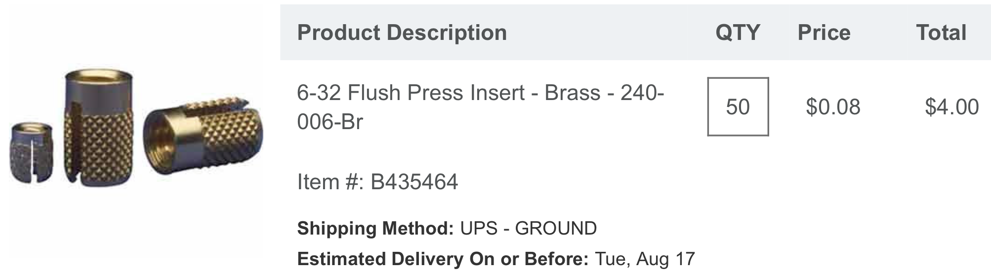
On the brass screw fittings for the side panels, I will send you some as I will get 50-pcs. 😊
For the RivNut, I bought everything in Amazon. Also in Amazon I bought the following parts to replace the old ones and they fit nicely into the H8 chassis. I think we can buy all the parts in Amazon for the H8 chassis…
https://www.amazon.com/dp/B0839KVBKB?psc=1&ref=ppx_yo2_dt_b_product_details

https://www.amazon.com/dp/B071ZM852H?psc=1&ref=ppx_yo2_dt_b_product_details

https://www.amazon.com/gp/product/B07MSHD726/ref=ppx_yo_dt_b_asin_title_o00_s00?ie=UTF8&psc=1
Thanks,
Norberto
From: "se...@googlegroups.com" <se...@googlegroups.com> on behalf of <glenn.f...@gmail.com>
Reply-To: "se...@googlegroups.com" <se...@googlegroups.com>
Date: Sunday, August 8, 2021 at 4:40 AM
To: "se...@googlegroups.com" <se...@googlegroups.com>
Subject: RE: [sebhc] H8 Tear down to check the new backplane.
Glenn Roberts
I will probably use a blank from Woodcraft:
https://www.woodcraft.com/categories/wood?thickness%5B%5D=3%2F4%22&width%5B%5D=6%22
thoughts suggestions welcome; also on stain and finish… possibly walnut or cherry… wondering of there was a particular wood or finish that was popular back in the 70s (e.g. for home stereos, etc.)?
From: se...@googlegroups.com <se...@googlegroups.com> On Behalf Of Norberto Collado
--
You received this message because you are subscribed to the Google Groups "SEBHC" group.
To unsubscribe from this group and stop receiving emails from it, send an email to sebhc+un...@googlegroups.com.
To view this discussion on the web visit https://groups.google.com/d/msgid/sebhc/A2DF9AAF-BB45-45FD-B6E1-6947C7249BCC%40koyado.com.
norberto.collado koyado.com
Sent: Monday, August 9, 2021 8:03 AM
Les Bird
norberto.collado koyado.com
Sent: Wednesday, August 11, 2021 9:47 AM
To: SEBHC <se...@googlegroups.com>
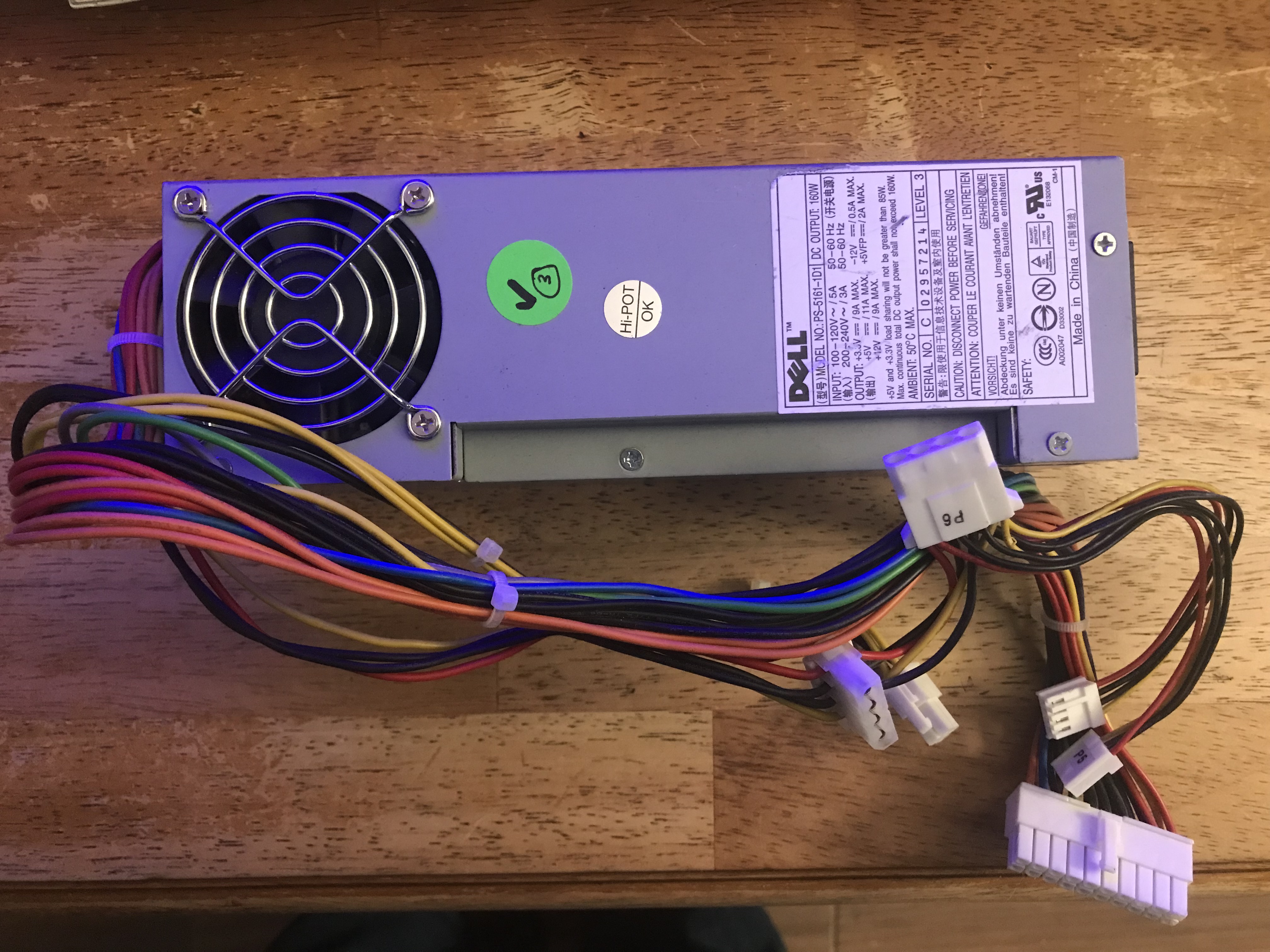
Steven Feinsmith
+3.3v @ 9A MAX
+5V @ 11A MAX
+12V @ 9A MAX
-12V @ 0.5A MAX
+5VFP @ 2A MAX
+5V and +3.3V load sharing will not be greater than 85W Max. continuous load DC output power shall not exceed 160W.
Here are two pictures to give you an idea:
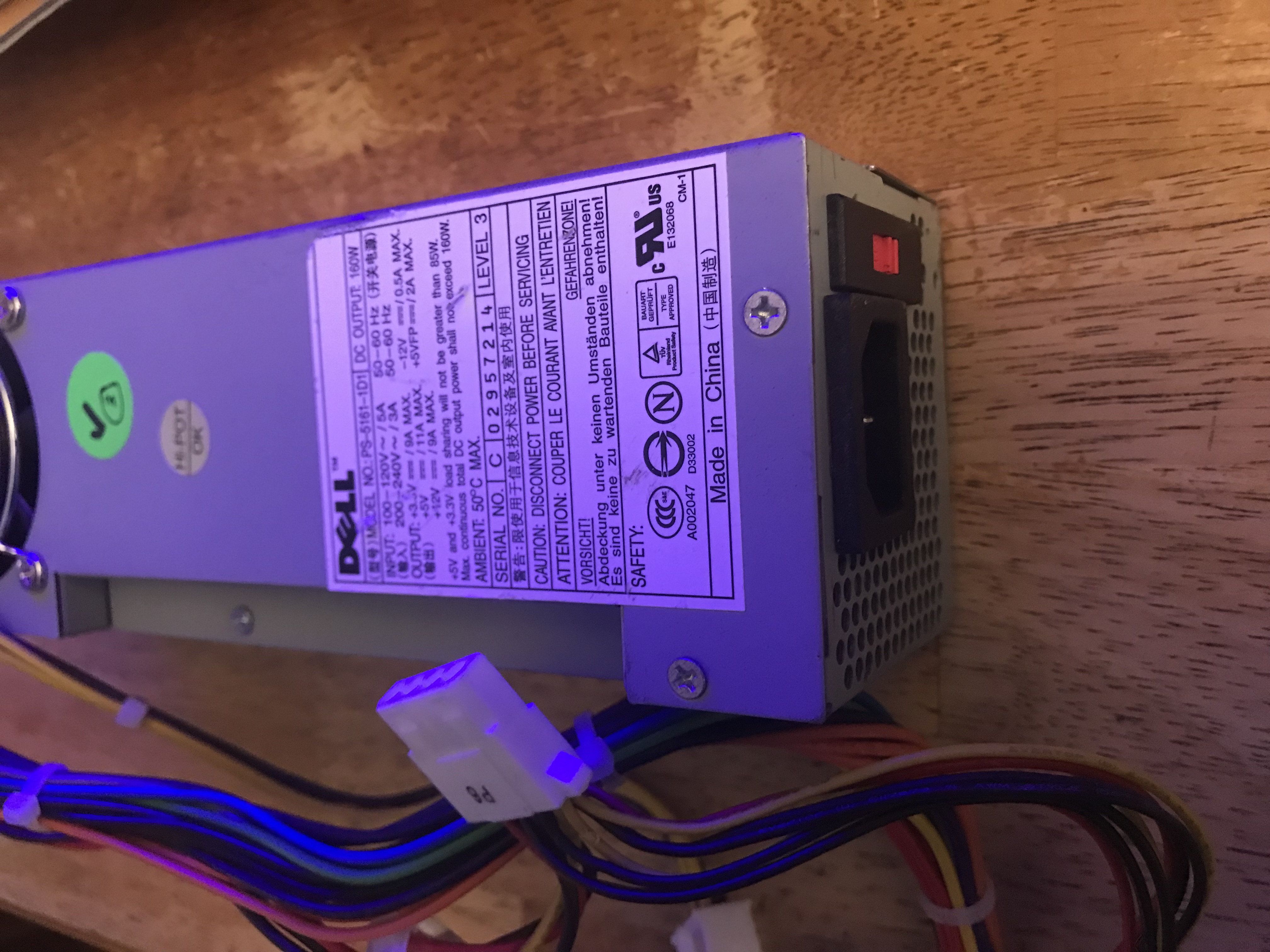
Thank you,
Steven
To view this discussion on the web visit https://groups.google.com/d/msgid/sebhc/a3832655-1af5-4af4-8957-1348d66f7168n%40googlegroups.com.
glenn.f...@gmail.com
I used an Athena Power model AP-MTFX30 in Rusty (which conforms to the “TFX” form factor specification):
https://photos.app.goo.gl/h1949iRCWefnuS7z6
it makes for a clean looking install because the fan grille lines up very nicely in the space where the transformer had been:
https://photos.app.goo.gl/LegyK8miY4oZLhP86
(however I did have to drill new holes).
the only problem is that the screws that hold the power supply to the case are those stubby coarse-threaded screws used in PC fans, and they’re screwed into plastic. If I ever shipped the unit I’d want to remove the power supply as I don’t trust those screws to hold it.
as you can see I never got around to adding a cord restraint for the power cord. I connected the switch to the appropriate power-on connections on the power supply (sorry can’t recall which lines those are but happy to report back more if needed).
On my “H8-2000” boards there were originally jumpers across input and output on all of the 5V regulators, but I’ve slowly added Pololu regulators to most of my boards so I can swap at will between PC-style and H8 analog powered chassis.
To view this discussion on the web visit https://groups.google.com/d/msgid/sebhc/SN6PR01MB38559616B4456BB747724B2EF7F89%40SN6PR01MB3855.prod.exchangelabs.com.
norberto.collado koyado.com
Sent: Wednesday, August 11, 2021 11:25 AM
G. Beat
greg
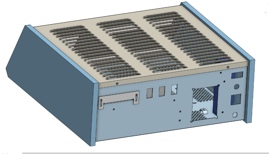
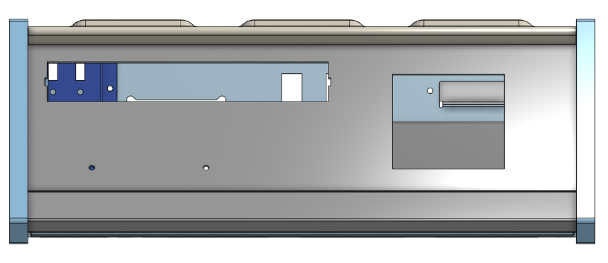
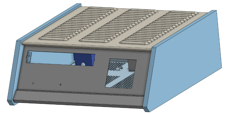
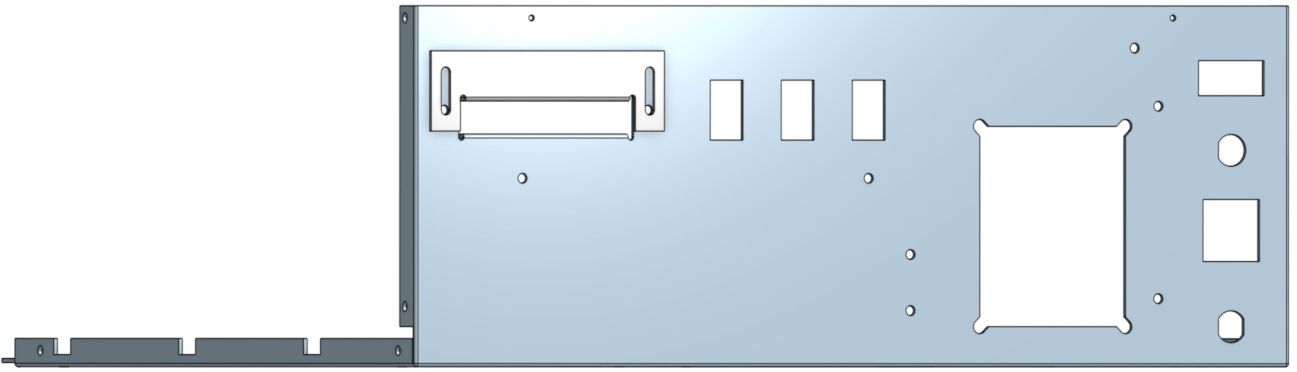
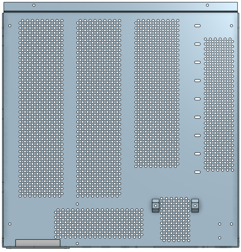
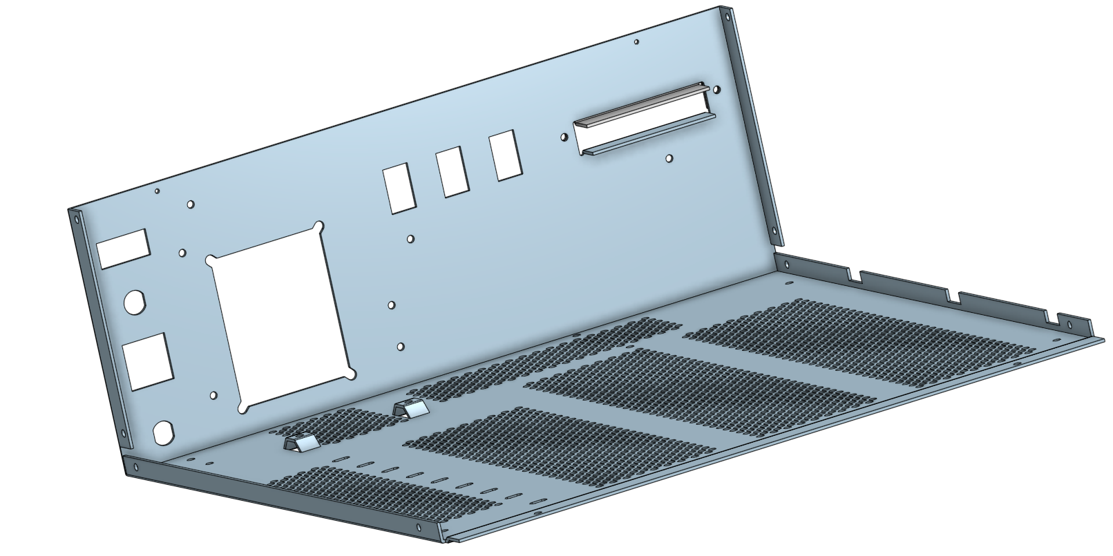
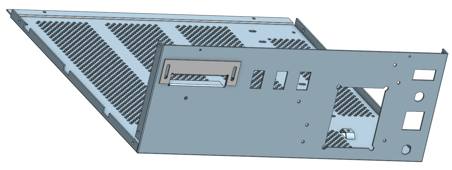
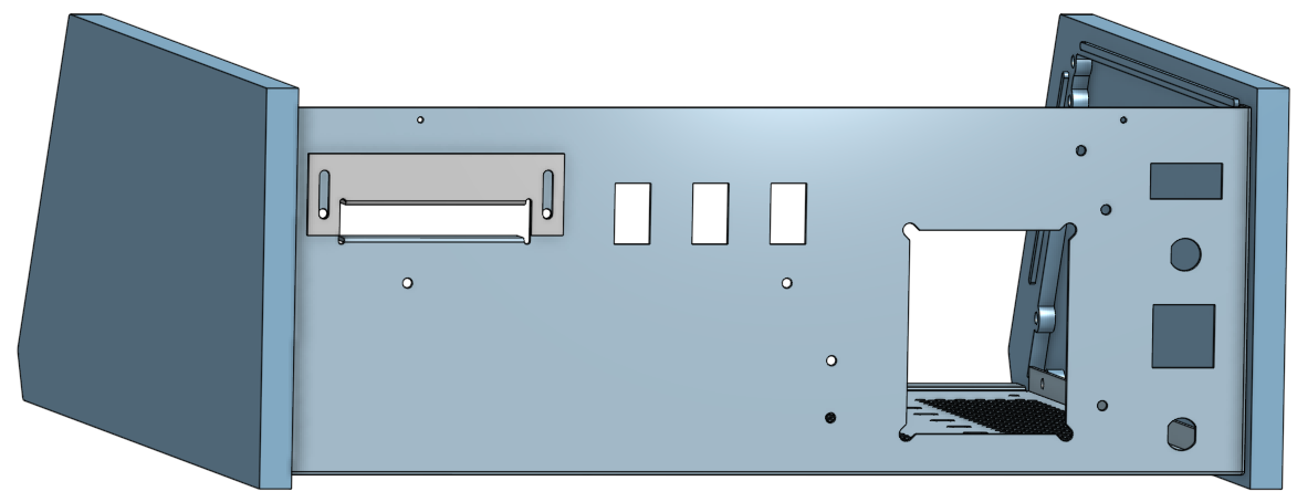
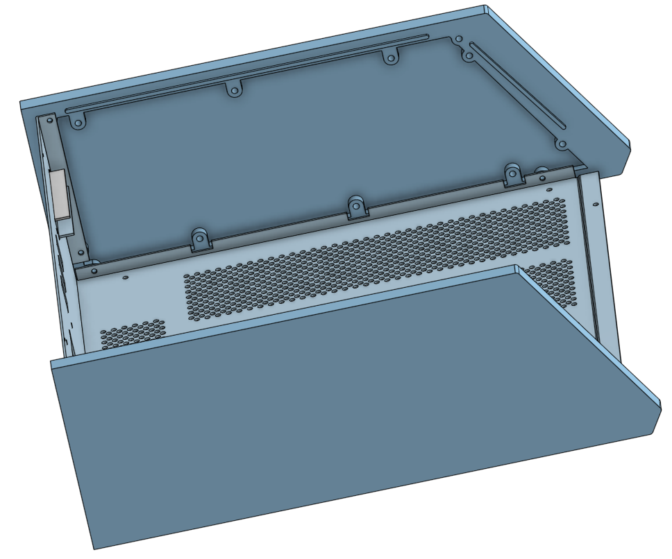
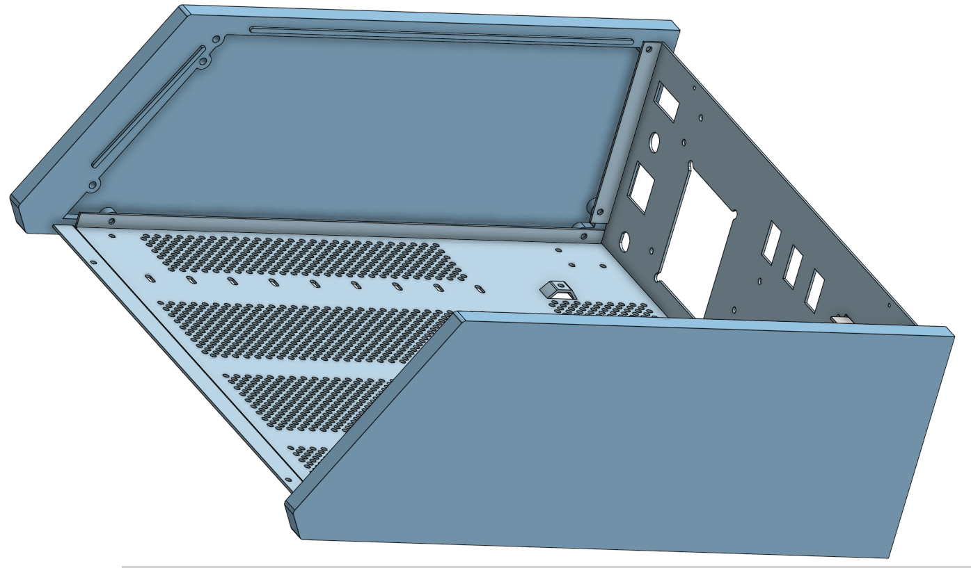
Norberto Collado
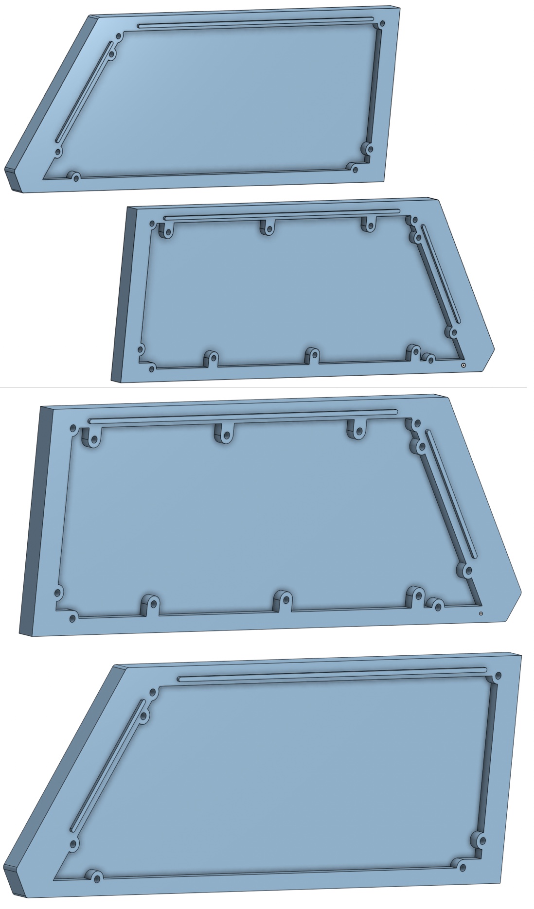
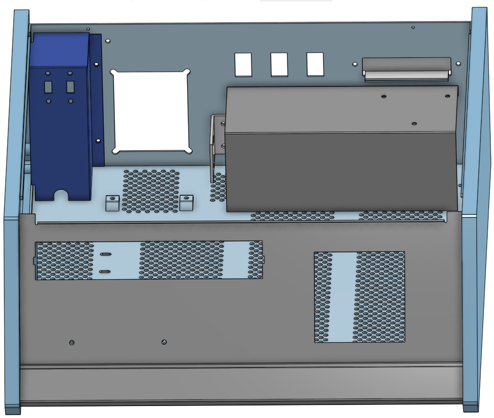
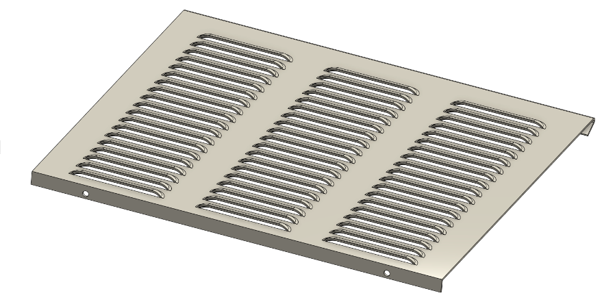
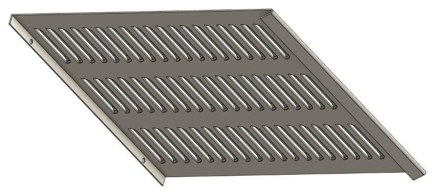
Latest pictures and we shall be done by this weekend in duplicating the original H8 chassis in CAD.
I did not realize until now that the H8 chassis is beautifully designed. Not like the PC that is a rectangular enclosure with no beauty in mind. I’m impressed that such small chassis could be that powerful.
Thanks,
Norberto
Glenn Roberts
On Aug 12, 2021, at 10:46 PM, Norberto Collado <norberto...@koyado.com> wrote:
Latest pictures and we shall be done by this weekend in duplicating the original H8 chassis in CAD.
I did not realize until now that the H8 chassis is beautifully designed. Not like the PC that is a rectangular enclosure with no beauty in mind. I’m impressed that such small chassis could be that powerful.
Thanks,
Norberto
<image001.png>
<image002.png>
<image003.png>
<image004.png>
<image005.png>
<image006.png>
--
You received this message because you are subscribed to the Google Groups "SEBHC" group.
To unsubscribe from this group and stop receiving emails from it, send an email to sebhc+un...@googlegroups.com.
To view this discussion on the web visit https://groups.google.com/d/msgid/sebhc/B5A15CD8-5C8A-482A-AF42-4D0B55B86A7E%40koyado.com.

Terry Smedley
Norberto Collado
Hello,
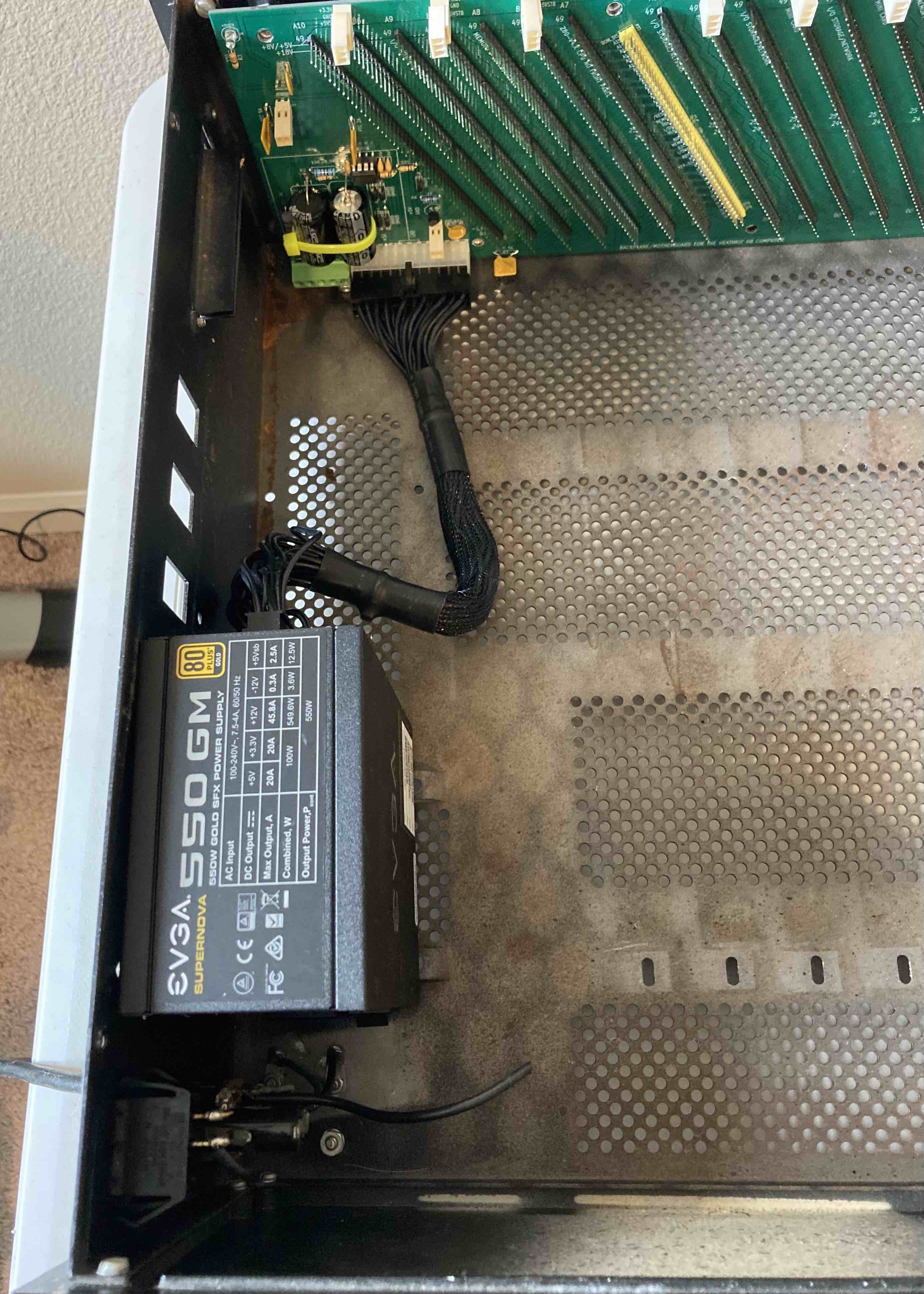
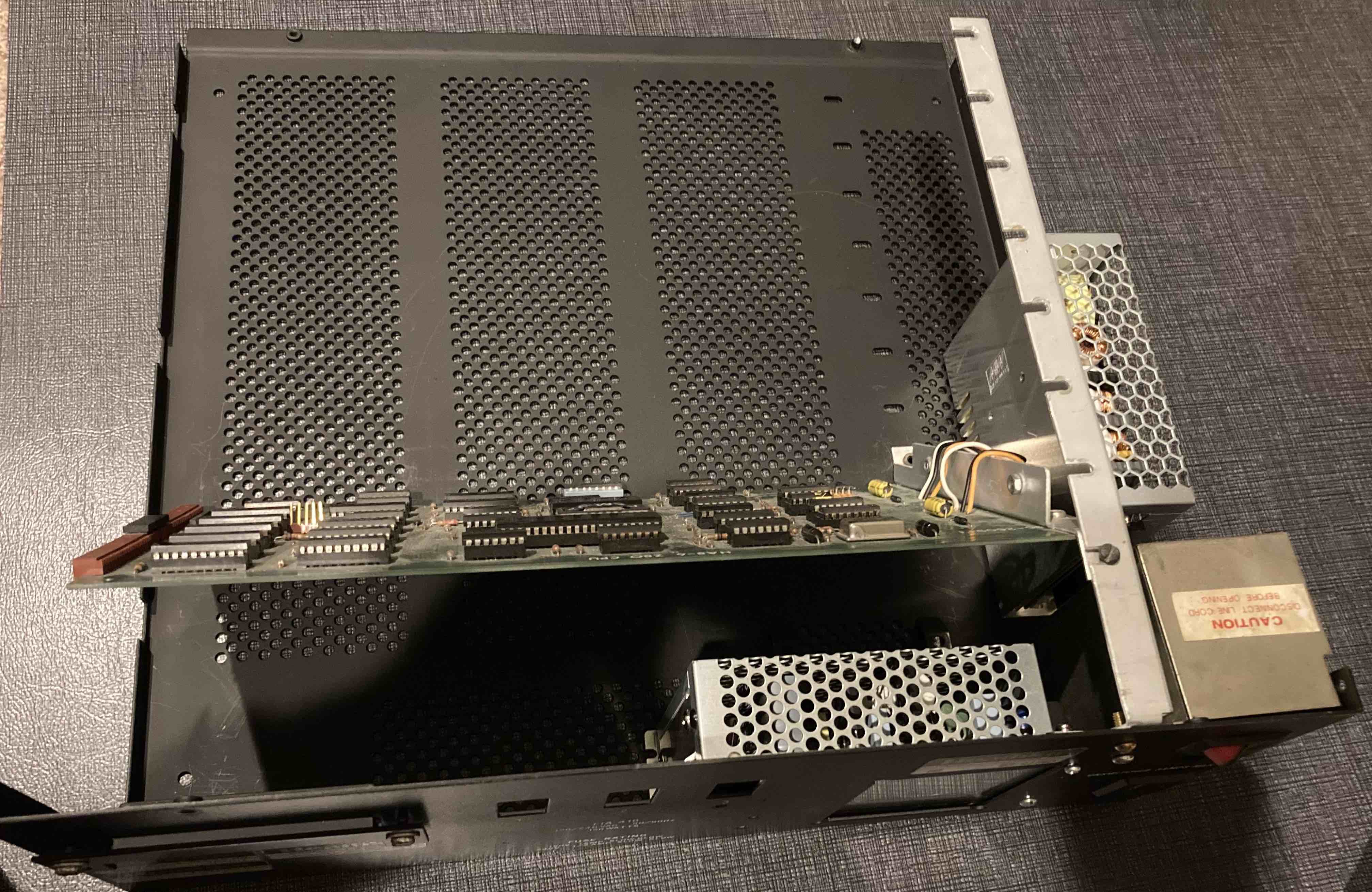
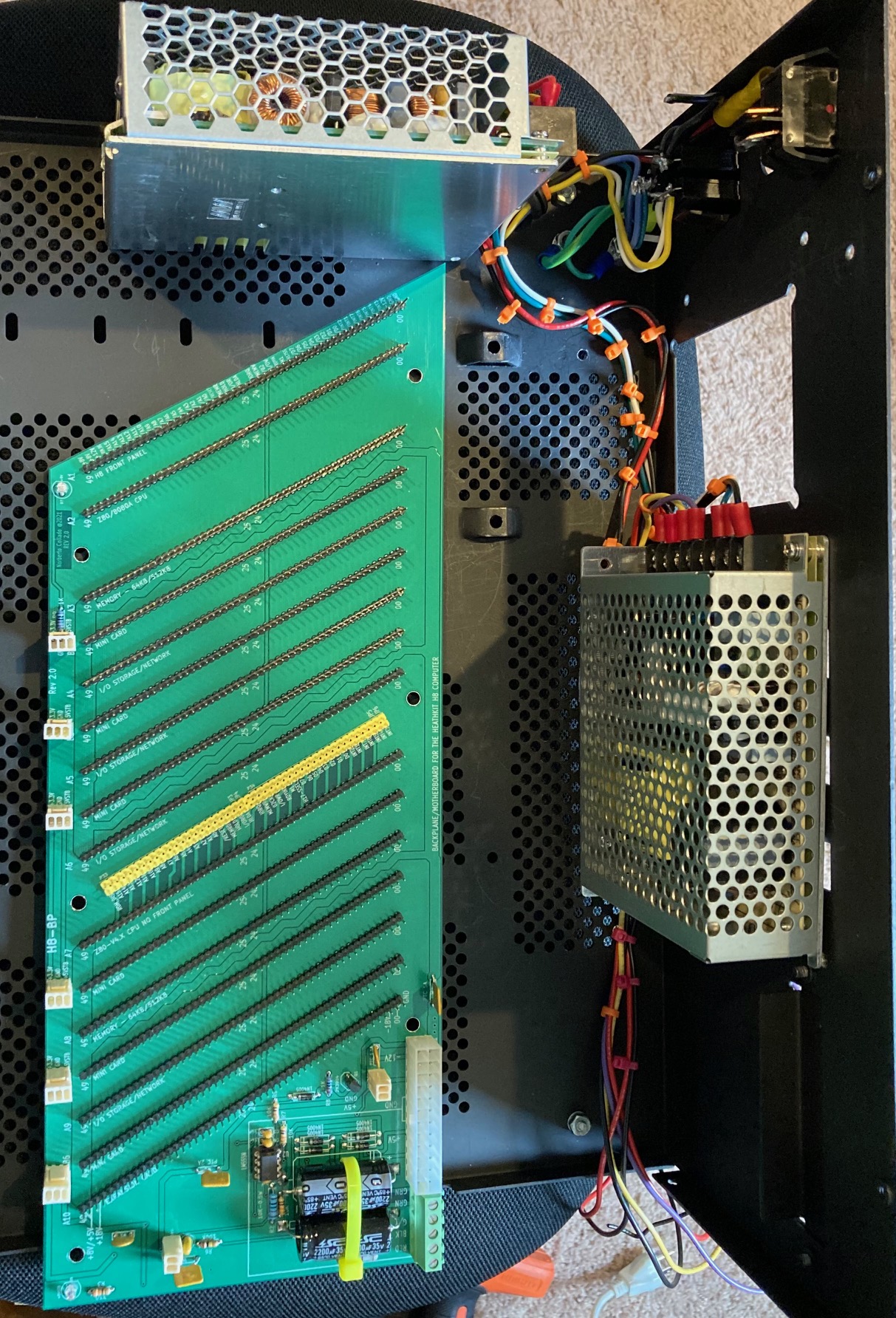
I completed testing with the ATX Power Supply on the H8 with the new backplane. It was hard to figure out on how to attached the ATX Power Supply into the H8 chassis.
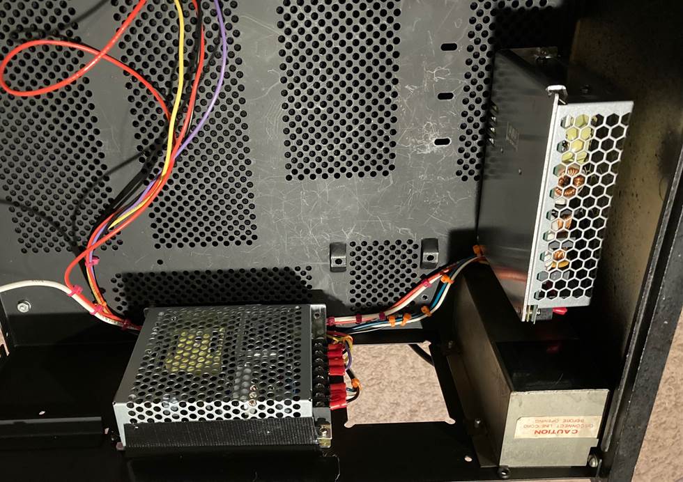
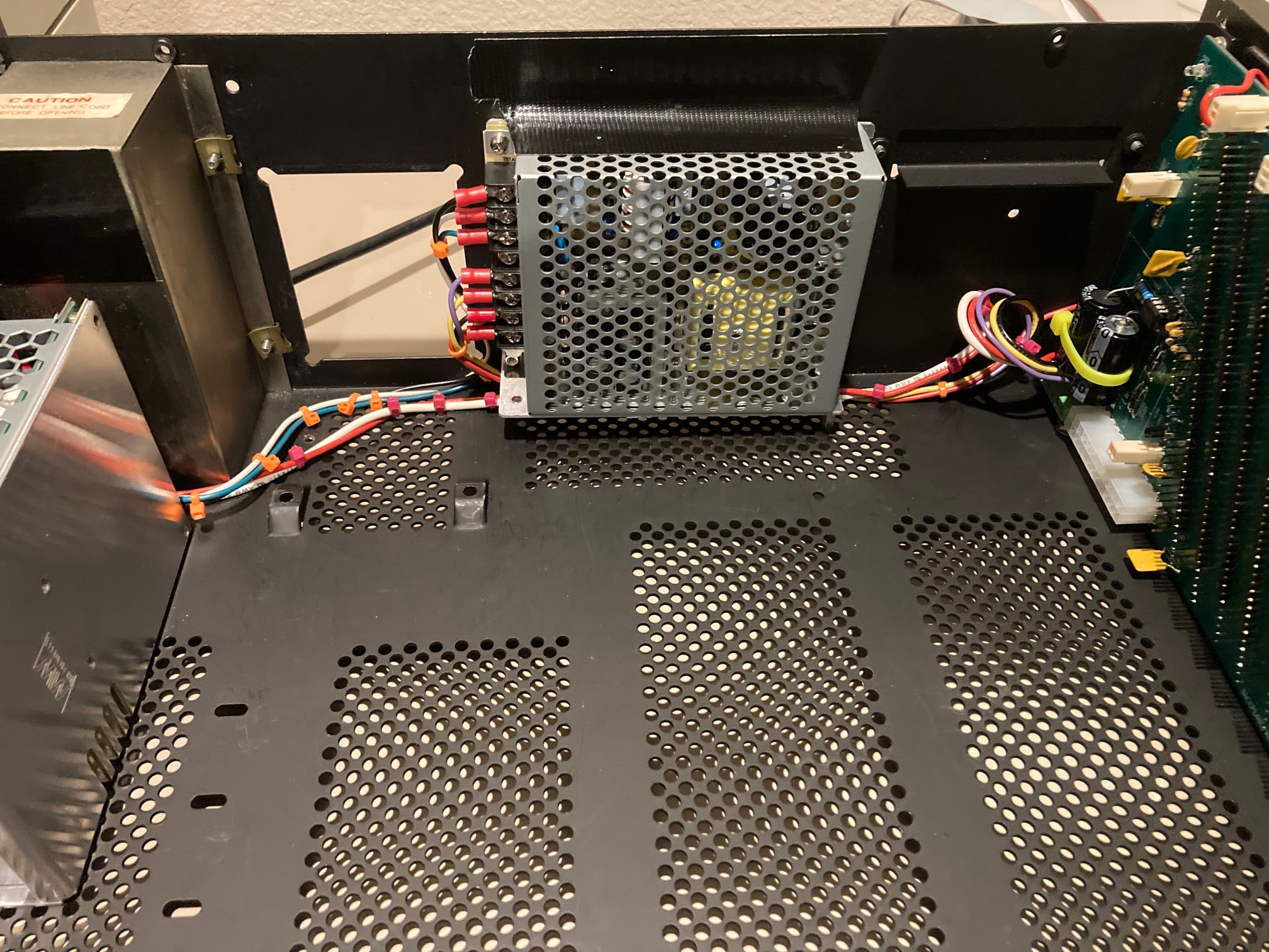
As I want to still support the 7805 regulators I decided to use two small power supplies. One for +15v/-15V around 1A, and a 8V power supply at 10A.
Here are some pictures with the two Power Supplies attached. I shall be able to start tomorrow in putting the system back. I just needed to drill two small holes as the second hole was already there. So both Power Supplies are secured.
I will use the fuse hole to attached a switch to provide reset to the second CPU board. More pictures to come.
Thanks,
Norberto
Norberto Collado
I have an H8 chassis that had previously been used as an expansion box on an old H8. There was a home-brew ribbon cable arrangement to string two busses together and (unfortunately) slots cut into the side panels to pass the ribbon cable through.
Glenn,
I asked my son to 3D print the side panels to verify alignment with the actual H8 chassis. Once I’m done, I will send you the two side panels. I already received the brass screws and will be installing them on the side panels.
Thanks,
Norberto
Glenn Roberts
I’ll certainly be anxious to see how the 3-D printing comes out! I can show this off at VCF East.
In fairness I should mention that I have repaired the holes in the side panels with a fairly good outcome. I’ll post pix and more info soon…
I’m still planning to make some wooden side panels as well, so I’ll have to get some of those brass inserts for that…
Thanks!
- Glenn
From: se...@googlegroups.com <se...@googlegroups.com> On Behalf Of Norberto Collado
Sent: Saturday, August 14, 2021 3:41 PM
To: se...@googlegroups.com
Subject: Re: [sebhc] H8 Tear down to check the new backplane.
I have an H8 chassis that had previously been used as an expansion box on an old H8. There was a home-brew ribbon cable arrangement to string two busses together and (unfortunately) slots cut into the side panels to pass the ribbon cable through.
--
You received this message because you are subscribed to the Google Groups "SEBHC" group.
To unsubscribe from this group and stop receiving emails from it, send an email to sebhc+un...@googlegroups.com.
To view this discussion on the web visit https://groups.google.com/d/msgid/sebhc/5F04BBCE-1E2B-4047-B68C-20A2B00190F9%40koyado.com.
Steven Feinsmith
The problem is metal sheets to create the top cover, bottom/rear end sheet, front panel, and some metal to support the cards. I am aware the cost of fabricating the metal is pretty expensive and must have a large volume. I do not know anyone who is tremendous still in metalworking to create parts. The situation is an enormous challenge at this time. I assume if we can find metalworking from China, it may be much cheaper to produce as many as 100 pieces. Any ideas?
Steven
To view this discussion on the web visit https://groups.google.com/d/msgid/sebhc/064001d7914c%24db587b30%2492097190%24%40gmail.com.
Paul Birkel
Consider creating an alternative top-panel using an array of perforations rather than louvers, which may then be less expensive to manufacture. Different look, of course …
To view this discussion on the web visit https://groups.google.com/d/msgid/sebhc/CAGJMgmUCAxa5T9BKibpmrKbuQuBgxjz7c2gt_oJwcdF6kermvg%40mail.gmail.com.
Steven Feinsmith
To view this discussion on the web visit https://groups.google.com/d/msgid/sebhc/034d01d791a1%24f2aa2cc0%24d7fe8640%24%40gmail.com.
Norberto Collado
Hello Glenn,
Sure, I will send you the brass inserts.
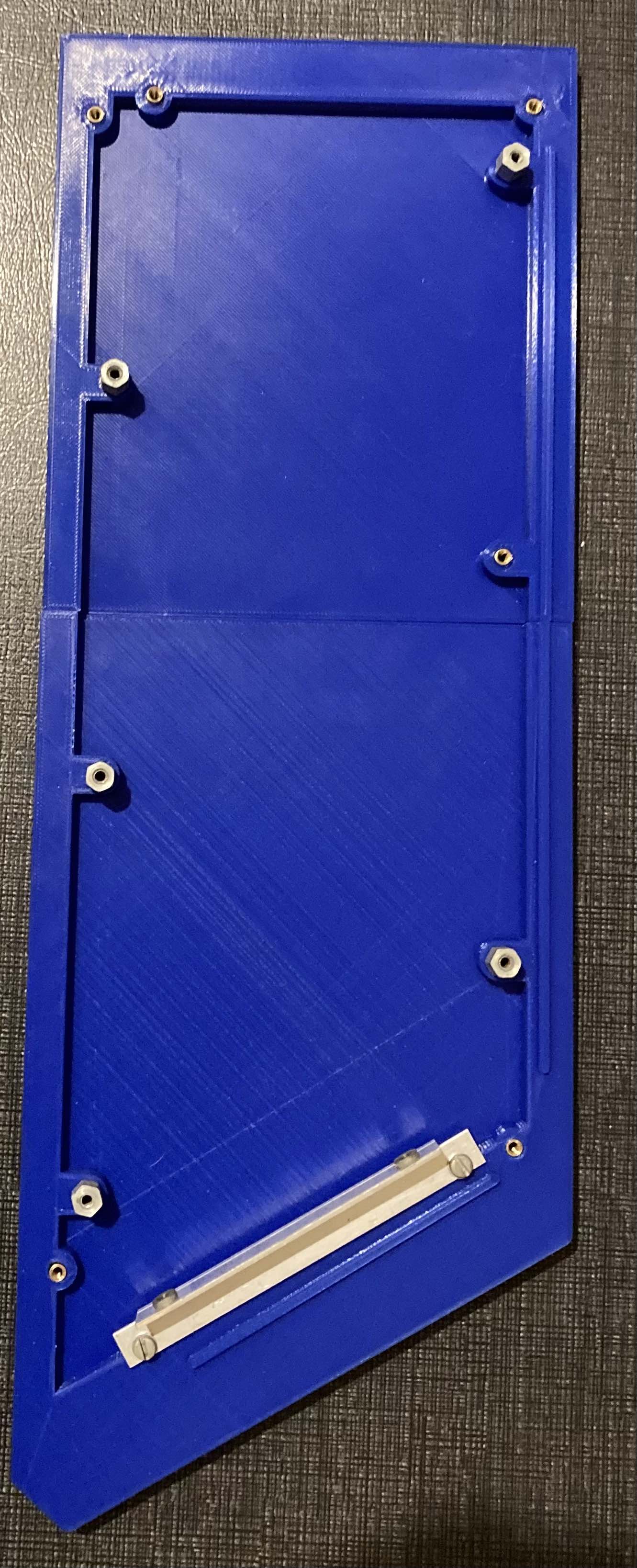
My son printed the right side panel. As his 3D printer is small, he printed it into 2 parts just to check alignment. He had to do some minor adjustments after installing it into the H8 chassis. Ink well spend. We will need to find a 3D print manufacturer that can handle bigger sizes.
Here is a picture of the 3D prototype.
Norberto

Norberto Collado
I do not think we need to add holes to the top of the enclosure. A small +12V fan attached to the side panel should do just fine. Or if using a PC power supply, the fan is built in.
Norberto
For the suggestion, using an array of perforations will look ugly appearance.
Thank you,
Steven
On Sun, Aug 15, 2021 at 2:51 AM Paul Birkel <pbi...@gmail.com> wrote:
Consider creating an alternative top-panel using an array of perforations rather than louvers, which may then be less expensive to manufacture. Different look, of course …
From: se...@googlegroups.com [mailto:se...@googlegroups.com] On Behalf Of Steven Feinsmith
Sent: Saturday, August 14, 2021 7:18 PM
To: se...@googlegroups.com
Subject: Re: [sebhc] H8 Tear down to check the new backplane.
Both sides can be created with wood or plastic through a milling machine. I know many people do not have that heavy machine. The alternative is to use your skill with a router, press drill, radial saw, and few others that can make excellent pieces of side replacement for the H-8.
The problem is metal sheets to create the top cover, bottom/rear end sheet, front panel, and some metal to support the cards. I am aware the cost of fabricating the metal is pretty expensive and must have a large volume. I do not know anyone who is tremendous still in metalworking to create parts. The situation is an enormous challenge at this time. I assume if we can find metalworking from China, it may be much cheaper to produce as many as 100 pieces. Any ideas?
Steven
.
glenn.f...@gmail.com
Very nice! So for this prototype are the two printed sections attached to each other somehow? How? Obviously for any serious production we’d need a single piece.
From: se...@googlegroups.com <se...@googlegroups.com> On Behalf Of Norberto Collado
Sent: Monday, August 16, 2021 1:08 AM
To: se...@googlegroups.com
Subject: Re: [sebhc] H8 Tear down to check the new backplane.
Hello Glenn,
--
You received this message because you are subscribed to the Google Groups "SEBHC" group.
To unsubscribe from this group and stop receiving emails from it, send an email to sebhc+un...@googlegroups.com.
To view this discussion on the web visit https://groups.google.com/d/msgid/sebhc/E70CD06F-E6A8-48F8-A26B-10D07086674D%40koyado.com.
norberto.collado koyado.com
Sent: Monday, August 16, 2021 5:06 AM
To: se...@googlegroups.com <se...@googlegroups.com>
Subject: RE: [sebhc] H8 Tear down to check the new backplane.
norberto.collado koyado.com
Glenn Roberts
I am no such expert but this chart is saying 16:
https://www.bluesea.com/resources/1437
I found a few others with similar info.
From: se...@googlegroups.com <se...@googlegroups.com> On Behalf Of norberto.collado koyado.com
Sent: Saturday, August 21, 2021 5:44 PM
To: se...@googlegroups.com
--
You received this message because you are subscribed to the Google Groups "SEBHC" group.
To unsubscribe from this group and stop receiving emails from it, send an email to sebhc+un...@googlegroups.com.
To view this discussion on the web visit https://groups.google.com/d/msgid/sebhc/SN6PR01MB3855113E1E1CE6DF0D3B6095F7C29%40SN6PR01MB3855.prod.exchangelabs.com.
Norberto Collado
Thanks Glenn!
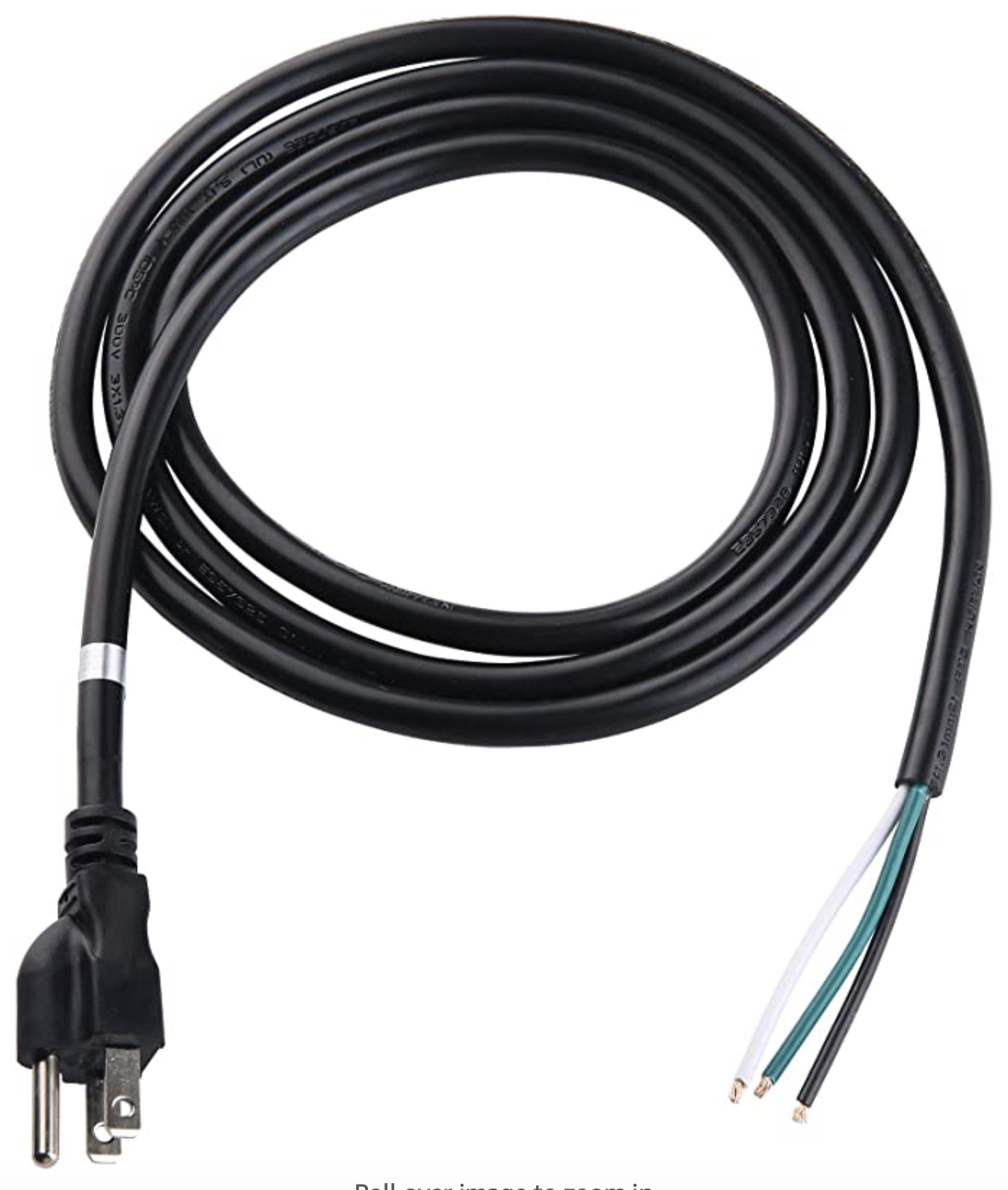
I found a white wire 16 AWG in my tool box and replaced both 18 AWG cables with this one. I colored the end in red, so that I know which one is ground and which one is positive.
Norberto
From: "se...@googlegroups.com" <se...@googlegroups.com> on behalf of Glenn Roberts <glenn.f...@gmail.com>
Reply-To: "se...@googlegroups.com" <se...@googlegroups.com>
Date: Saturday, August 21, 2021 at 5:48 PM
To: "se...@googlegroups.com" <se...@googlegroups.com>
To view this discussion on the web visit https://groups.google.com/d/msgid/sebhc/074001d796ef%245d17ccf0%24174766d0%24%40gmail.com.

Lee Hart
To view this discussion on the web visit https://groups.google.com/d/msgid/sebhc/54319F1F-D718-4FFC-8569-ED9842AFC8B7%40koyado.com.
norberto.collado koyado.com
Sent: Monday, August 23, 2021 12:39 PM
To: se...@googlegroups.com <se...@googlegroups.com>
norberto.collado koyado.com
Sent: Monday, August 23, 2021 9:25 PM
Steven Feinsmith
To view this discussion on the web visit https://groups.google.com/d/msgid/sebhc/SN6PR01MB3855088FC70524E253ECDCBEF7C59%40SN6PR01MB3855.prod.exchangelabs.com.
Norberto Collado
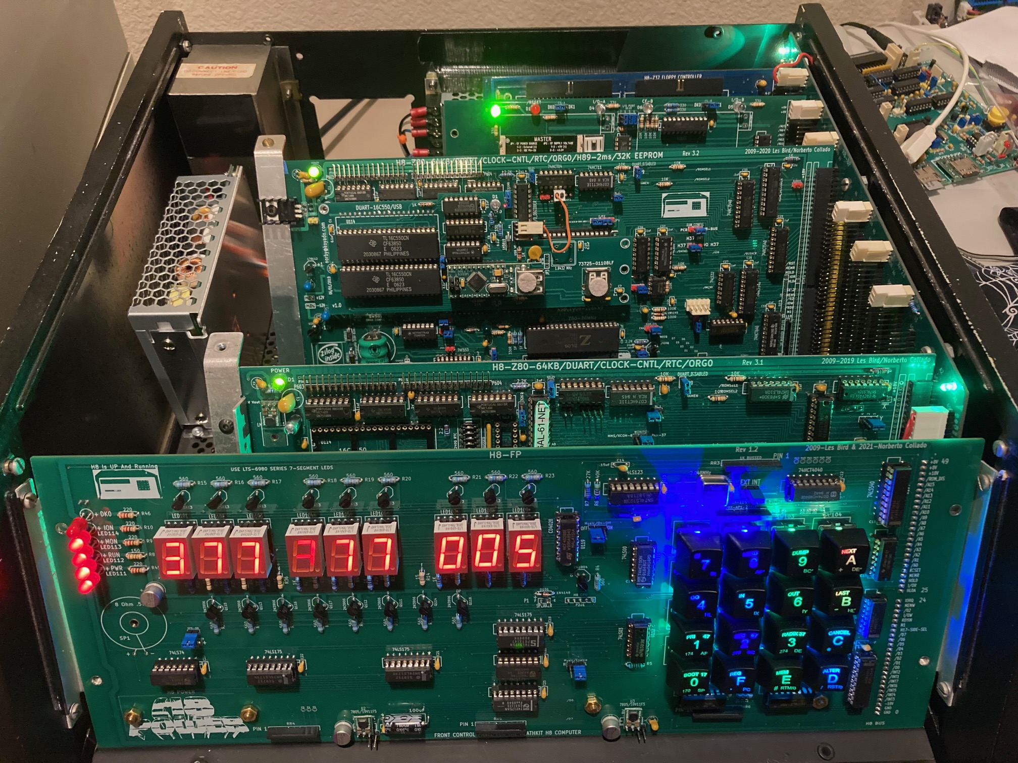
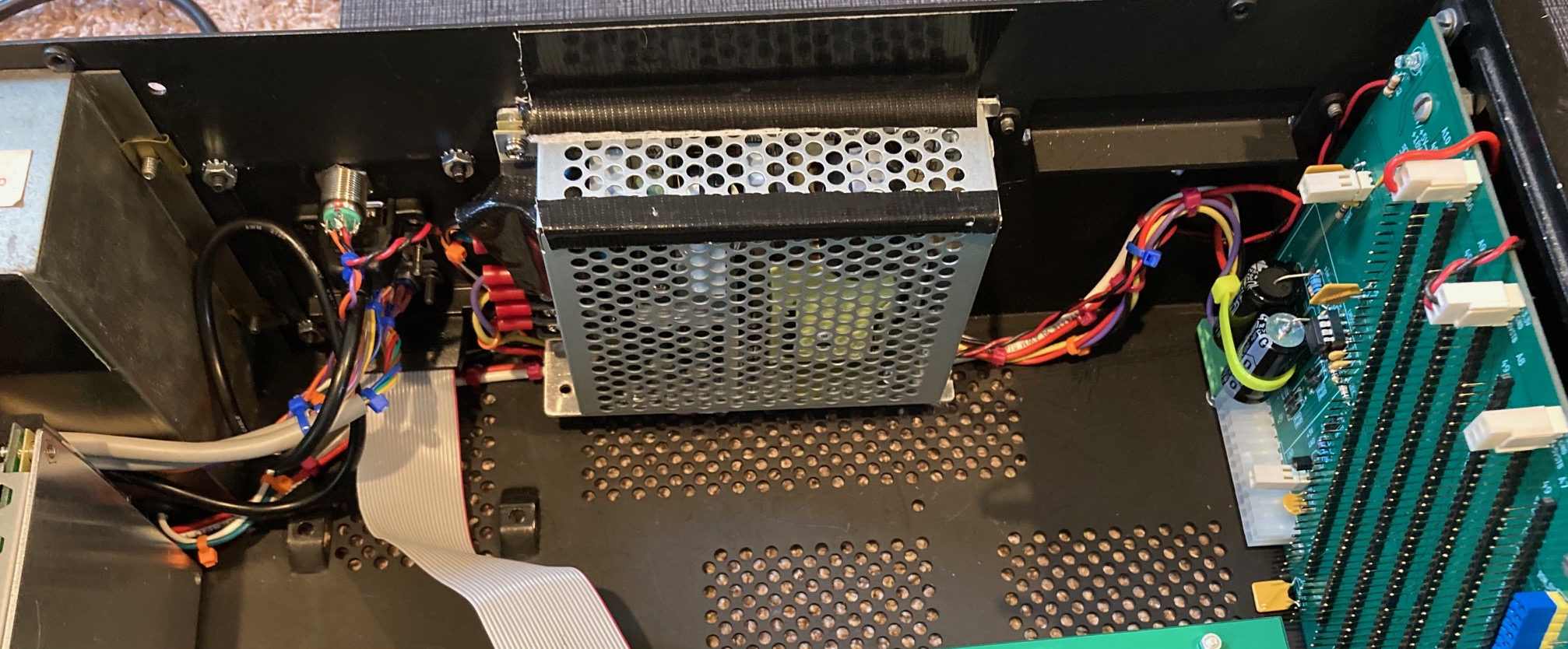
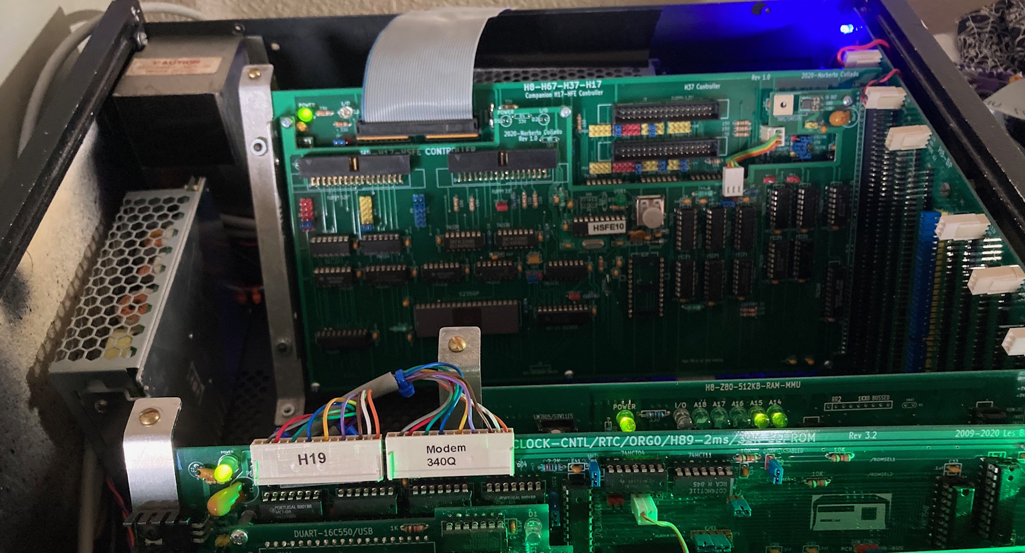
Powered-up the updated H8 system and it came up nicely. Now I have less weight on the chassis and I can use last slot on the H8 backplane with space still left. Below is a two CPU configuration to do a quick verification that the main CPU was still operational.
One power supply provides +8Volts and the second power supply provides +5V,+15V, and -15V to support legacy Heath boards.
Here are some pictures.
Thanks,
Norberto

Glenn Roberts
On Sep 2, 2021, at 2:42 AM, norberto...@koyado.com wrote:
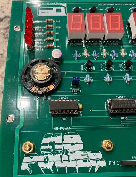
Adding mini speaker to H8 Front Panel!
<image003.jpg>
--
You received this message because you are subscribed to the Google Groups "SEBHC" group.
To unsubscribe from this group and stop receiving emails from it, send an email to sebhc+un...@googlegroups.com.
To view this discussion on the web visit https://groups.google.com/d/msgid/sebhc/024a01d79fc5%24c311b410%2449351c30%24%40koyado.com.
glenn.f...@gmail.com
Did you just hot glue that to attach it?
From: se...@googlegroups.com <se...@googlegroups.com> On Behalf Of norberto...@koyado.com
Sent: Thursday, September 02, 2021 2:43 AM
To: se...@googlegroups.com
Subject: RE: [sebhc] H8 Tear down to check the new backplane.
Adding mini speaker to H8 Front Panel!

--
You received this message because you are subscribed to the Google Groups "SEBHC" group.
To unsubscribe from this group and stop receiving emails from it, send an email to sebhc+un...@googlegroups.com.
To view this discussion on the web visit https://groups.google.com/d/msgid/sebhc/024a01d79fc5%24c311b410%2449351c30%24%40koyado.com.
Norberto Collado
I added a little hot glue on one side, but the soldered wires can do the job. The sound of such speaker is soft and not as loud as the original. For me that works better as it doesn’t bother my ears when beeping. Also my wife approved it as the original sound was loud and bother her as well.
On the stiffening bar, it is not needed for the production boards. The FP pictured here is my first prototype which is thinner than the production board and requires such bar. Also this proto board is missing a lot of features.
Thanks,
Norberto
From: "se...@googlegroups.com" <se...@googlegroups.com> on behalf of <glenn.f...@gmail.com>
Reply-To: "se...@googlegroups.com" <se...@googlegroups.com>
Date: Thursday, September 2, 2021 at 9:26 AM
To: "se...@googlegroups.com" <se...@googlegroups.com>
Subject: RE: [sebhc] H8 Tear down to check the new backplane.
Did you just hot glue that to attach it?
From: se...@googlegroups.com <se...@googlegroups.com> On Behalf Of norberto...@koyado.com
Sent: Thursday, September 02, 2021 2:43 AM
To: se...@googlegroups.com
Subject: RE: [sebhc] H8 Tear down to check the new backplane.
Adding mini speaker to H8 Front Panel!

--
You received this message because you are subscribed to the Google Groups "SEBHC" group.
To unsubscribe from this group and stop receiving emails from it, send an email to sebhc+un...@googlegroups.com.
To view this discussion on the web visit https://groups.google.com/d/msgid/sebhc/024a01d79fc5%24c311b410%2449351c30%24%40koyado.com.
--
You received this message because you are subscribed to the Google Groups "SEBHC" group.
To unsubscribe from this group and stop receiving emails from it, send an email to sebhc+un...@googlegroups.com.
To view this discussion on the web visit https://groups.google.com/d/msgid/sebhc/007a01d7a017%243c606040%24b52120c0%24%40gmail.com.
Lee Hart
To view this discussion on the web visit https://groups.google.com/d/msgid/sebhc/2995B434-2E77-49A4-B943-438BA52D702F%40koyado.com.
norberto...@koyado.com
Thanks for the feedback. I will check voltage drop as I add boards to find out if gauge is correct.
Norby
From: se...@googlegroups.com <se...@googlegroups.com> On Behalf Of Lee Hart
Sent: Thursday, September 2, 2021 9:21 PM
To: se...@googlegroups.com
To view this discussion on the web visit https://groups.google.com/d/msgid/sebhc/CAF__8heX-NQM5AMYF-aY881sTHakk9yxXhC7g06hAsPi07dGJA%40mail.gmail.com.
Glenn Roberts
On Sep 3, 2021, at 3:05 AM, norberto...@koyado.com wrote:
<image001.jpg>
--
You received this message because you are subscribed to the Google Groups "SEBHC" group.
To unsubscribe from this group and stop receiving emails from it, send an email to sebhc+un...@googlegroups.com.
To view this discussion on the web visit https://groups.google.com/d/msgid/sebhc/024a01d79fc5%24c311b410%2449351c30%24%40koyado.com.--
You received this message because you are subscribed to the Google Groups "SEBHC" group.
To unsubscribe from this group and stop receiving emails from it, send an email to sebhc+un...@googlegroups.com.
To view this discussion on the web visit https://groups.google.com/d/msgid/sebhc/007a01d7a017%243c606040%24b52120c0%24%40gmail.com.
--
You received this message because you are subscribed to the Google Groups "SEBHC" group.
To unsubscribe from this group and stop receiving emails from it, send an email to sebhc+un...@googlegroups.com.
To view this discussion on the web visit https://groups.google.com/d/msgid/sebhc/2995B434-2E77-49A4-B943-438BA52D702F%40koyado.com.
--
You received this message because you are subscribed to the Google Groups "SEBHC" group.
To unsubscribe from this group and stop receiving emails from it, send an email to sebhc+un...@googlegroups.com.
To view this discussion on the web visit https://groups.google.com/d/msgid/sebhc/CAF__8heX-NQM5AMYF-aY881sTHakk9yxXhC7g06hAsPi07dGJA%40mail.gmail.com.
--
You received this message because you are subscribed to the Google Groups "SEBHC" group.
To unsubscribe from this group and stop receiving emails from it, send an email to sebhc+un...@googlegroups.com.
To view this discussion on the web visit https://groups.google.com/d/msgid/sebhc/02d001d7a092%24047f7410%240d7e5c30%24%40koyado.com.
norberto.collado koyado.com
Norberto Collado
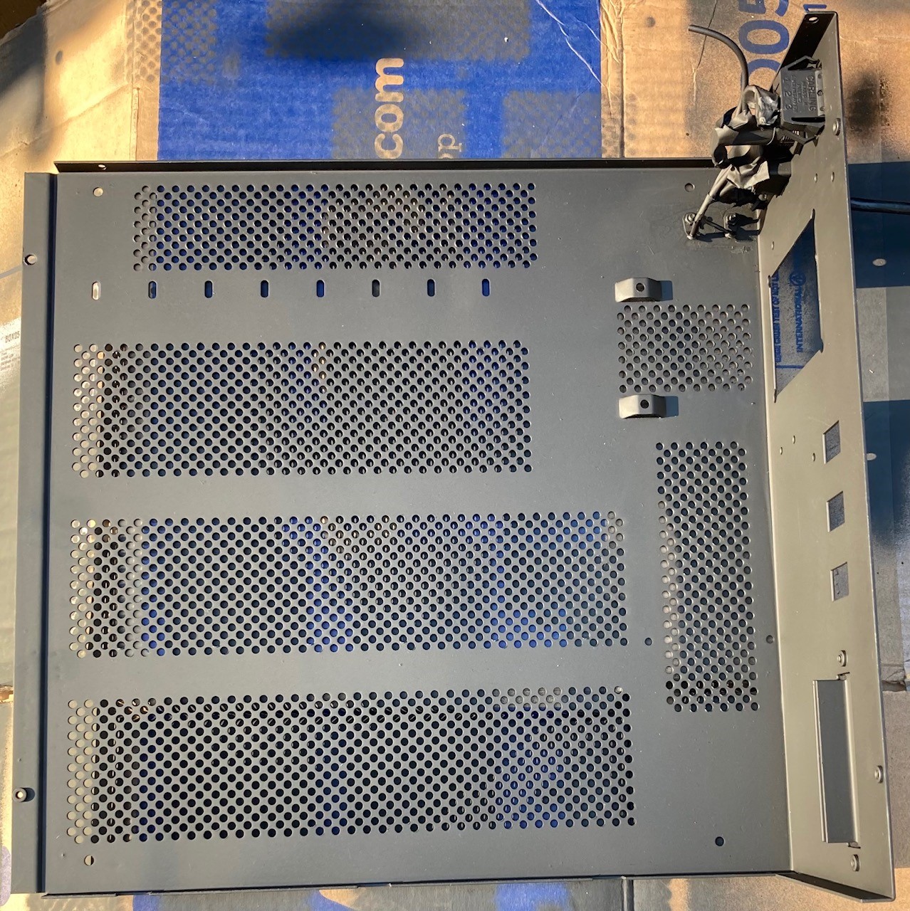
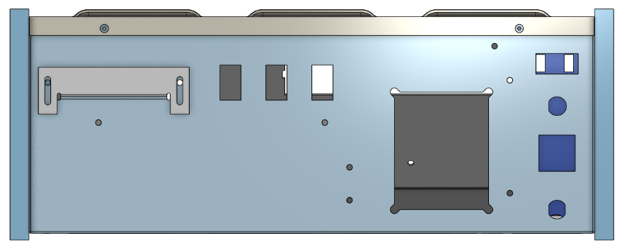
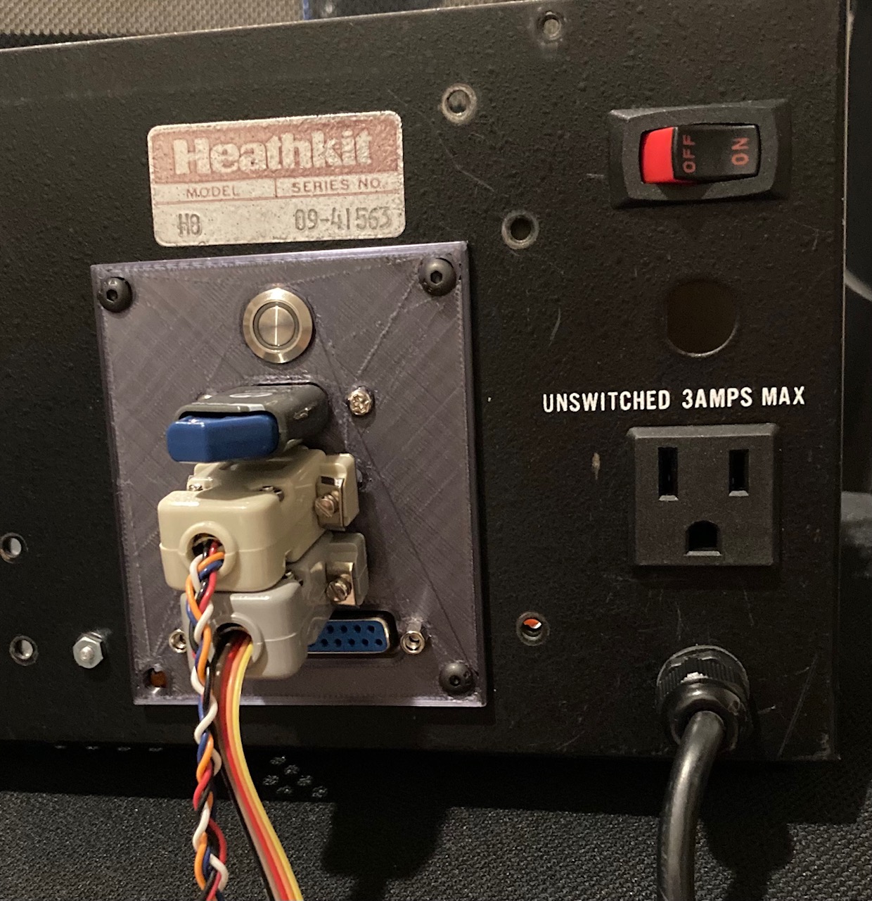
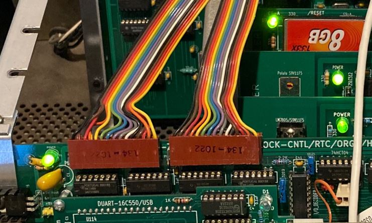
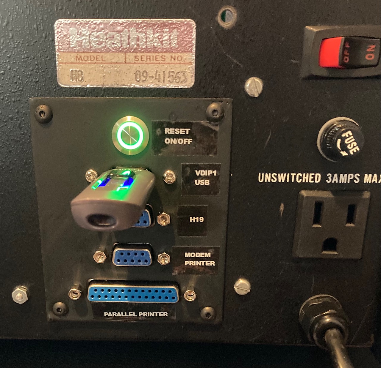
Today added the I/O cover plate to H8 system, so that cable management is more cleaner.
Here are some pictures:
Glenn Roberts
On Sep 18, 2021, at 8:42 PM, Norberto Collado <norberto...@koyado.com> wrote:
Today added the I/O cover plate to H8 system, so that cable management is more cleaner.
Here are some pictures:
<image001.jpg>
<image002.jpg>
<image003.jpg>
--
You received this message because you are subscribed to the Google Groups "SEBHC" group.
To unsubscribe from this group and stop receiving emails from it, send an email to sebhc+un...@googlegroups.com.
To view this discussion on the web visit https://groups.google.com/d/msgid/sebhc/910DF7F9-00C4-4E3F-BE8D-86962582BF74%40koyado.com.
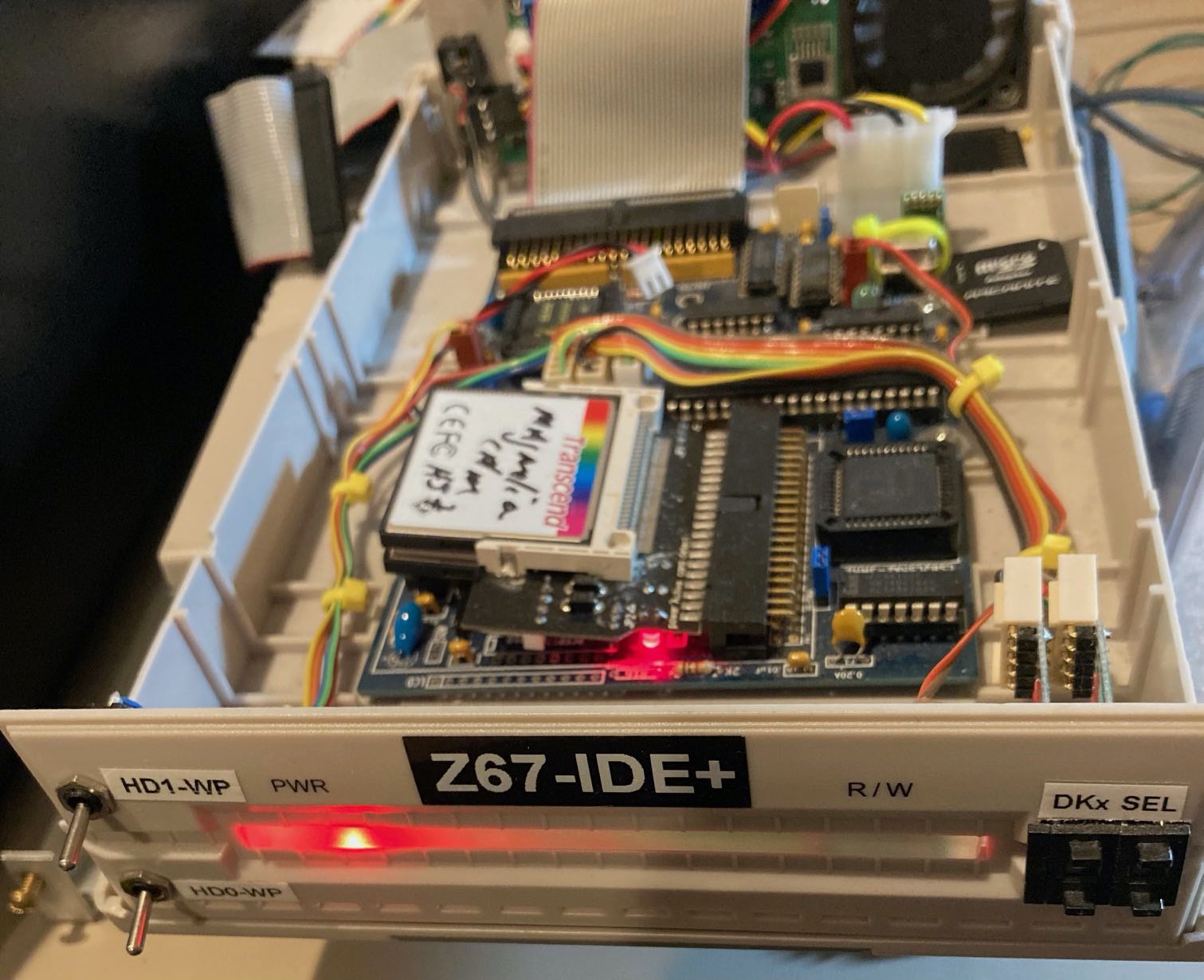
Norberto Collado
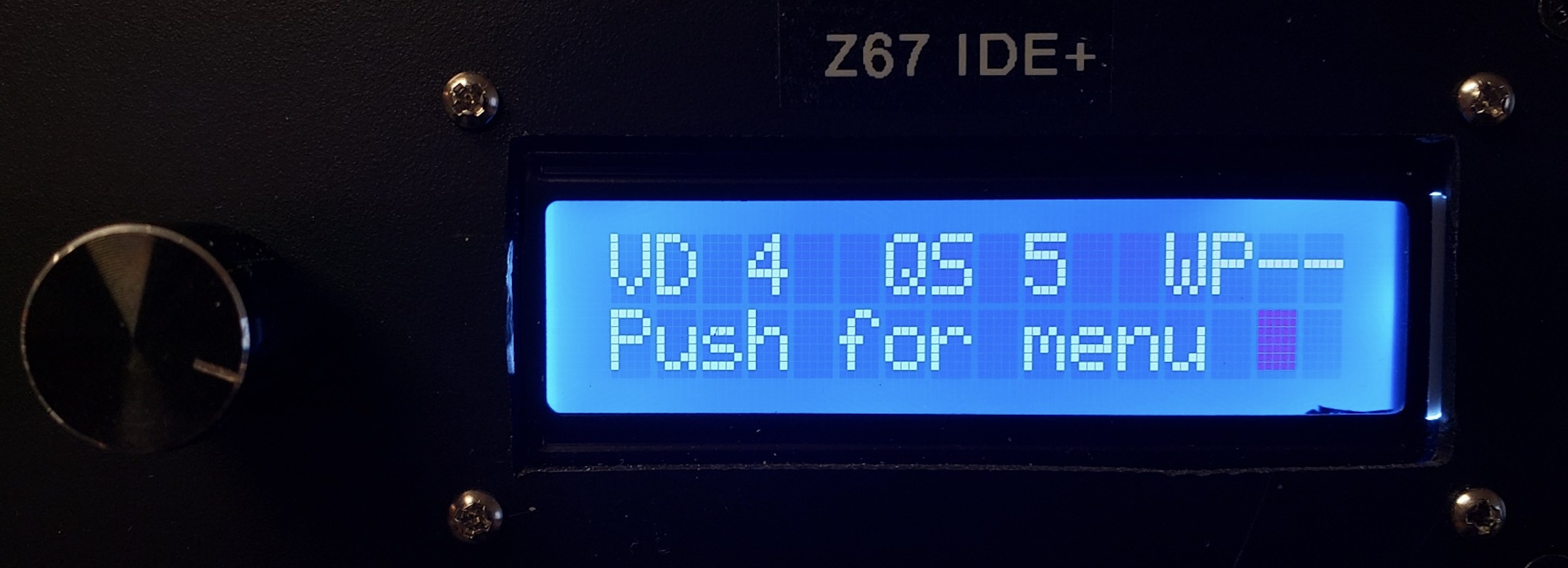
Yes! They are on the external enclosure with the Z67-IDE+. I just bring the SASI cable out to it. Also looking into using the solution provided by Terry S. which uses the Rotary Encoder Module to manage the LCD Menu.
Terry S. solution to eliminate the BCD switches:
Thanks,
Norberto
From: "se...@googlegroups.com" <se...@googlegroups.com> on behalf of Glenn Roberts <glenn.f...@gmail.com>
Reply-To: "se...@googlegroups.com" <se...@googlegroups.com>
Date: Saturday, September 18, 2021 at 7:37 PM
To: "se...@googlegroups.com" <se...@googlegroups.com>
Subject: Re: [sebhc] H8 Tear down to check the new backplane.
Very nice!
To view this discussion on the web visit https://groups.google.com/d/msgid/sebhc/0697967B-80DB-47F0-AF82-B6C26581BE99%40gmail.com.