H4 electrics - inertia switch

jul...@cityaudioservices.com
Hi
My H4 cut out unexpectedly at the MoT garage after being driven into the brake test equipment which involved the car being grounded! Looking at the circuit diagram there are several potential reasons why this happened, most of which I know how to diagnose and where to look. But one possible potential problem is the impact sensor which is shown in the Haynes manual.
Does anyone know if these are usually refitted in an H4 and if so is there a 'standard' location? It might help me locate it without having to dismantle the entire vehicle. If anyone has a photo of the actual unit I'm looking for, that would also help.
Thanks

Steve Kodź
Julian,
Not sure about a standard location, but I think the wiring would naturally position this in the passenger foot well area. Mine was attached to the chassis door pillar in the passenger foot well.
Regards,
Steve
--
--
You received this message because you are subscribed to the Google Groups "Quantum Owners Group" group.
To post to this group, send email to quantu...@googlegroups.com
To unsubscribe from this group, send email to quantumowner...@googlegroups.com
For more options, visit this group at http://groups.google.com/group/quantumowners?hl=en
IMPORTANT NOTE: All information presented herewith is provided on an "As Is" basis, without warranty or the implication thereof. Neither the Quantum Owners Club nor the individuals associated with the Quantum Owners Club or in the preparation of the above information shall have any liability to any person or entity with respect to liability, loss, or damage caused or alleged to be caused directly or indirectly by the instructions contained within this or related message(s).
---
You received this message because you are subscribed to the Google Groups "Quantum Owners Group" group.
To unsubscribe from this group and stop receiving emails from it, send an email to quantumowner...@googlegroups.com.
To view this discussion on the web visit https://groups.google.com/d/msgid/quantumowners/2e4407ca4fc9662be81484ffd7216a42%40cityaudioservices.com.
--
h4-turbo.co.uk
quantumowners.club

Jim Hearne

susanandmartin
As Steve said, near the door (A) pillar is a common place. In a Mondeo (company car) a work colleague had a flat tyre and changed it, then the vehicle wouldn’t start – you can imagine he was pretty exasperated. It turned out the inertia switch was in the boot near where he dropped the punctured tyre/wheel!
Martin Scott
Sent from Mail for Windows 10
From: 'Steve Kodź' via Quantum Owners Group
Sent: 23 September 2022 13:41
To: quantu...@googlegroups.com
Subject: Re: [Quantum Owners] H4 electrics - inertia switch
Julian,
To view this discussion on the web visit https://groups.google.com/d/msgid/quantumowners/dfa91925-364d-fc3b-148b-c97bdb2ad201%40h4-turbo.co.uk.
jul...@cityaudioservices.com
All
I'm assuming from what I can see on the web it's likely to be a small flattish black box.
Fingers crossed I can find it.
Thanks as ever for the help
To view this discussion on the web visit https://groups.google.com/d/msgid/quantumowners/632daff7.1c0a0220.47bb6.259bSMTPIN_ADDED_MISSING%40gmr-mx.google.com.
Jim Hearne
jul...@cityaudioservices.com
That's useful - I was expecting it to be smaller than that. At least slimmer!
To view this discussion on the web visit https://groups.google.com/d/msgid/quantumowners/9D8F365D445A493997B80CC298043697%40JimQuad.
jul...@cityaudioservices.com
An update:
I'm now pretty sure it is the impact/inertia sensor. Power goes to and through the fuse but doesn't get to the pump. Whilst it could be a cable fault, it's unlikely. However I cannot find the damn thing! To get it running I have provided a separate feed. Next step is to get the car in the air to check it's not near the tank. Then I guess it will be off with the dash! The wiring under there is shocking - every time I look I find another in line fuse just hanging around - so I do want to do that as soon as I can. But there is an endless (if shortening) list of things to do - as always.
Regards
On 2022-09-23 14:33, Jim Hearne wrote:
To view this discussion on the web visit https://groups.google.com/d/msgid/quantumowners/9D8F365D445A493997B80CC298043697%40JimQuad.
jul...@cityaudioservices.com
Hi
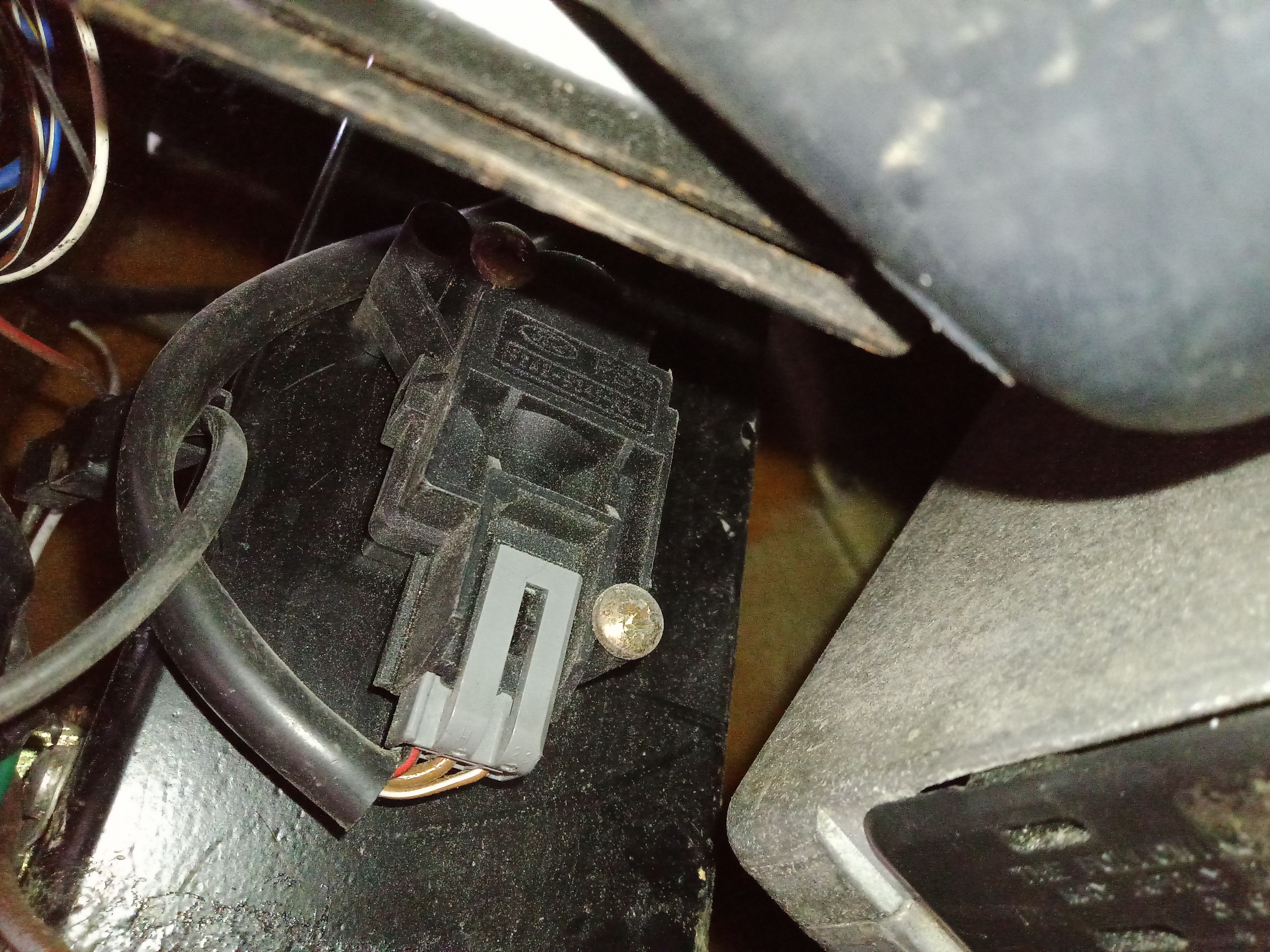
I have found an air bag sensor (though there are none in the car of course) and close by another potential suspect - see attached. It's the right sort of size but has three connections where the manual says two, although one appears at least to be the right colour code. Also it has no reset button. However what it does have at the top is a cylinder which might once have been the housing for a plunger.
I haven't yet tried testing anything like circuit tracing because the plastic of the connector look easy to break. If it is the right unit, I will attempt to remove it and see if it can be reset.
Alternatively do you know if a replacement might be obtained?
Julian
On 2022-09-23 14:33, Jim Hearne wrote:
To view this discussion on the web visit https://groups.google.com/d/msgid/quantumowners/9D8F365D445A493997B80CC298043697%40JimQuad.

Pete M
jul...@cityaudioservices.com
Thanks for confirmation. Unfortunately there is no button unless it is deep inside the tube at the top. I can't feel anything in there. I'll probably have to extract the thing and see if I find something to push on.
--
--
You received this message because you are subscribed to the Google Groups "Quantum Owners Group" group.
To post to this group, send email to quantu...@googlegroups.com
To unsubscribe from this group, send email to quantumowner...@googlegroups.com
For more options, visit this group at http://groups.google.com/group/quantumowners?hl=en
IMPORTANT NOTE: All information presented herewith is provided on an "As Is" basis, without warranty or the implication thereof. Neither the Quantum Owners Club nor the individuals associated with the Quantum Owners Club or in the preparation of the above information shall have any liability to any person or entity with respect to liability, loss, or damage caused or alleged to be caused directly or indirectly by the instructions contained within this or related message(s).
---
You received this message because you are subscribed to the Google Groups "Quantum Owners Group" group.
To unsubscribe from this group and stop receiving emails from it, send an email to quantumowner...@googlegroups.com.
To view this discussion on the web visit https://groups.google.com/d/msgid/quantumowners/ffc8072f-2f00-468e-a631-7eded105e6e2n%40googlegroups.com.

list...@liberator-systems.co.uk
jul...@cityaudioservices.com
Thanks for the additional information, very useful.
To view this discussion on the web visit https://groups.google.com/d/msgid/quantumowners/a8e919eb-fcf6-44ac-85b7-21f2b2cb0d7bn%40googlegroups.com.
jul...@cityaudioservices.com
Hi
Further investigation is proving tricky. Having removed the connector and so gained access to the loom wiring I can find no link from the fuse (F19) to the connector and no link from the connector to the now cut feed wire to the pump (there being a temporary positive feed to the pump to keep it going). Both should exist. None of the three wires connect to ground or indicate power at any time.
The only explanation I can think of is that the unit was problematic and it has been short circuited and it is that connection which has failed. My problem of course is I have no idea where that might be. So the hunt will go on.
Incidentally the unit is certainly the impact sensor. I managed to read the part number and found one on e-bay and despite it being from a Ka it is identical - except mine does not have the red button, just a hole where the red button should be! So perhaps that explains the disconnection theory. It broke so it was dispensed with. Anyway, I have the e-bay unit on order.
The part incidentally is F2AB-9341-AA.
Now I just have to find the bodge.
Regards and thanks for all the help
Jim Hearne
>>The part incidentally is F2AB-9341-AA.
That part number is too new to have come from the donor car.
Has this car got a Mk4 or Mk5 Fiesta dash fitted ?
Jim
jul...@cityaudioservices.com
It's a standard dash so far as I know with the only mod (I believe) being the instruments - see attached.
To view this discussion on the web visit https://groups.google.com/d/msgid/quantumowners/5090B06A2674472B9F515791204A6253%40JimQuad.
jul...@cityaudioservices.com
A thought. I have noticed that the fuse box/relay holder is different from the Haynes photo. It does not have the three fuses to the right of the relay tray (ie hidden from view unless the tray is unhitched and dropped down, it only has the extension on the left. I assumed this was merely that Haynes simply showed one model with and ignored the variant without.
I don't know if that may be relevant.
On 2022-09-26 12:17, Jim Hearne wrote:
To view this discussion on the web visit https://groups.google.com/d/msgid/quantumowners/5090B06A2674472B9F515791204A6253%40JimQuad.
Jim Hearne
jul...@cityaudioservices.com
OK, so the chances are the loom is Mk3. The engine is a 2l Mondeo, the lights are the Morette mod and the loom is a shambles, I've found three extra fuses in the cabin and several more in the engine bay.
I do also have an alarm - fitted by a prior owner. I was wondering about that being the culprit, but it works by not allowing the car to be turned over. However finding that both leads to and from the sensor are apparently not connected suggests it is not the alarm cutting power to the sensor.
That leaves the possibility that the alarm is faulty and is interrupting the pump power feed which doesn't go through the sensor.
More investigation required clearly. Or I fit the new impact sensor and route an entirely new power feed.
To view this discussion on the web visit https://groups.google.com/d/msgid/quantumowners/188F33EEA94E4745B7103E7D3132006B%40JimQuad.
Jim Hearne
jul...@cityaudioservices.com
I had come to that conclusion :-(
However given that the original shock sensor is not in the feed circuit I may just fit the new one and wire it independently. That way I get to have a shock sensor again, but one I can find and monitor. Meanwhile I can get a a lot of the suspect wiring and work my way through it.
To view this discussion on the web visit https://groups.google.com/d/msgid/quantumowners/67514768B06F4D5C87E770EA93E43C4F%40JimQuad.
jul...@cityaudioservices.com
As I mentioned I found an identical inertia switch to the one fitted and ordered it on the basis that the loom must have been modded for it. I will of course drop it in and see if it works, but i seriously doubt it will because nothing seems to be connected.
So on the assumption that I have to wire it up, does anyone have access to details of how the Ka unit should be wired?
Julian
On 2022-09-26 12:59, Jim Hearne wrote:
To view this discussion on the web visit https://groups.google.com/d/msgid/quantumowners/67514768B06F4D5C87E770EA93E43C4F%40JimQuad.
Jim Hearne
jul...@cityaudioservices.com
Thanks for all your efforts. I had assumed that the two heavy cables ought to be the fuel pump feed in/out. But it's best to be certain!
I'll do some tests to see if there is any way to diagnose function.
Regards
On 2022-09-27 12:16, Jim Hearne wrote:
It's very strange, i've just been through the wiring diagrams for every Ford i can think of up to around 2000 and none have a 3 pin inertia switch.
To view this discussion on the web visit https://groups.google.com/d/msgid/quantumowners/4EB14D1E135B44F38BDA6274725B1565%40JimQuad.