shear_moment_diagram
25 views
Skip to first unread message

Alejandro Stewart
Nov 18, 2020, 3:54:07 AM11/18/20
to pyNastran Discuss
Hello,
![]()
![]()
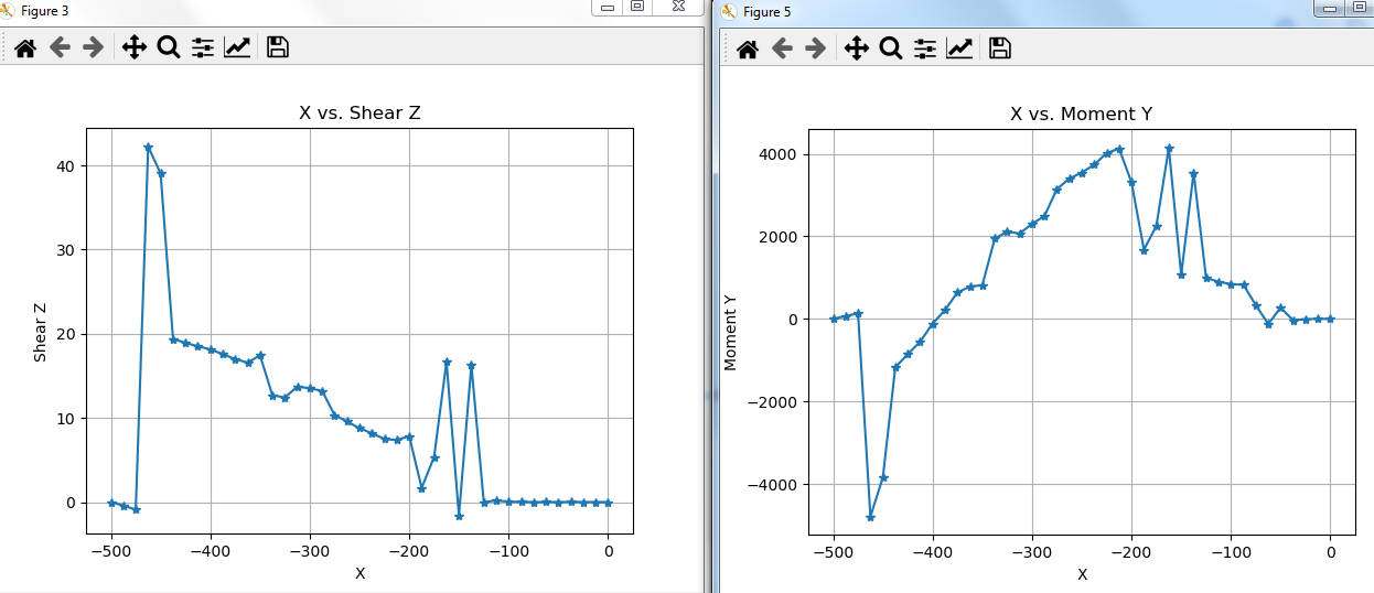
I have been playing arround with the shear_moment_diagram functionality from GPFORCES but the results are far from what I expected. I have idealized an aircraft as a beam, simply supported with gravity plus a RBE2 for tail load. The shear and bending diagrams should be pretty simple but what I get is really messy and the numbers d not match my predictions, nor the freebody analysis in hyperview.
Note: suppor SPC`s are at -330 approx
My question is, is this routine working or am I soing something wrong? The simplified
model and results + script are in the attache zip file.
Alejandro
Alejandro Stewart
Nov 18, 2020, 3:56:30 AM11/18/20
to pyNastran Discuss
I tried to embed 2 pictures but I can´t see them, I attach them here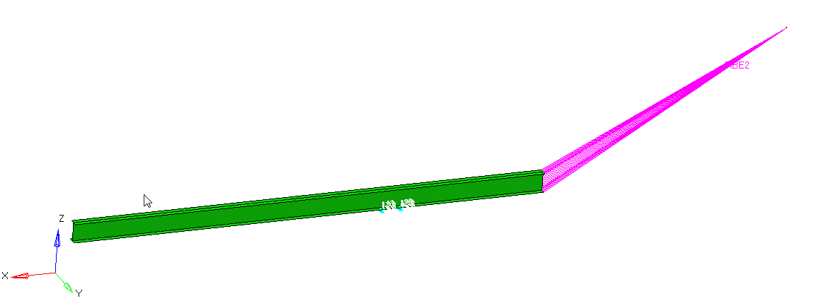

Steven Doyle
Nov 18, 2020, 1:40:47 PM11/18/20
to pyNastran Discuss
What do you expect the SMT plots to look like? I'm not really sure what you intend for the direction of torque (x) or the two shear directions (y, z)?
Maybe a little background might help. The output coordinate system is independent of the direction that you are marching. If you select your starting/end points correctly, you should see the number of nodes/elements march from about the total to ~0 (or vice versa).
--
You received this message because you are subscribed to the Google Groups "pyNastran Discuss" group.
To unsubscribe from this group and stop receiving emails from it, send an email to pynastran-disc...@googlegroups.com.
To view this discussion on the web visit https://groups.google.com/d/msgid/pynastran-discuss/8ed398e6-4591-449b-b243-6cf423eba424n%40googlegroups.com.
Alejandro Stewart
Nov 30, 2020, 5:49:47 AM11/30/20
to pyNastran Discuss
I was expecting an internal forces diagram, but, correct me if I am wrong, what we get with this method is the sum of all forces in the node (applied, spc, element, MPC)
Steven Doyle
Nov 30, 2020, 2:13:21 PM11/30/20
to pyNastran Discuss
You should get the internal forces diagram. I guess what my question was is that is just an I beam and I don't know what direction you're trying to march in. You could march down the wing or you could march down the fuselage.
I'm expecting something like you're trying to march spanwise down the 1/4 chord of the swept and tapered wing. Thus, the start is at the centerline=[100,0,0] and the end is at the wingtip=[150,200,0]. The the output coordinate axes march down the wing, but are rotated relative to the direction of integration and align with the global coordinate system.
Could you also add some CAERO1s (for the wing and tail) and a CROD (for the fuselage) to indicate geometry?
To view this discussion on the web visit https://groups.google.com/d/msgid/pynastran-discuss/7cc5d89b-d7dd-41b5-afaa-f5e16f54c06en%40googlegroups.com.
Alejandro Stewart
Dec 1, 2020, 11:59:17 PM12/1/20
to pyNastran Discuss
Oh, sorry, I meant I was marching along x, from nose to tail.
Reply all
Reply to author
Forward
0 new messages