PDP8 with OS/8 on a postage stamp
690 views
Skip to first unread message

Ian Schofield
Feb 18, 2022, 12:45:48 PM2/18/22
to PiDP-8
Dear All,
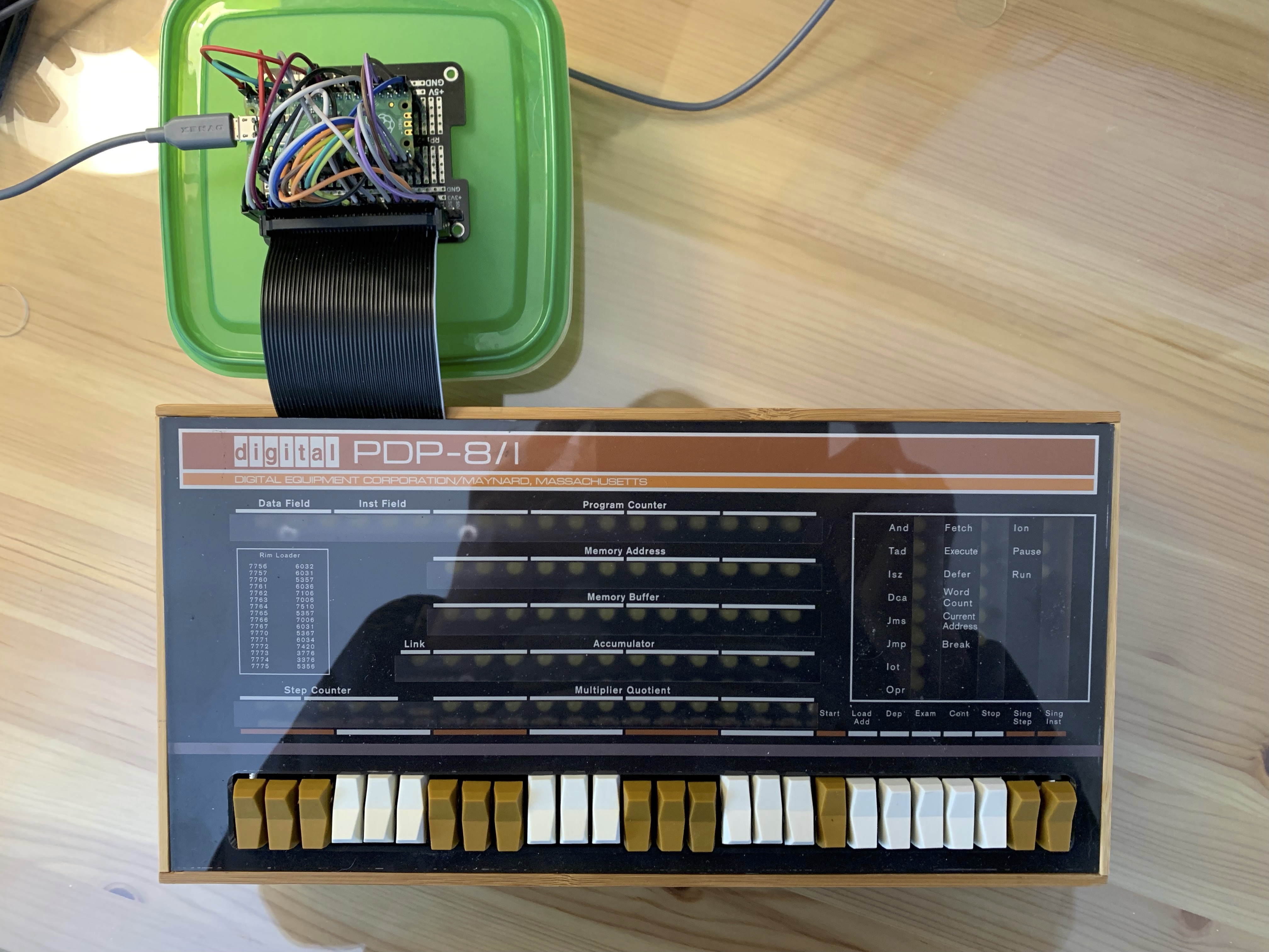
I apologise if this is a bit off topic but it may be of interest to some of you. Pimeroni Tiny 2040 – Pimoroni have released a tiny RP2040 (Pi Pico) module with 8MB flash. This is the size of a postage stamp and being of a certain demographic, I could not resist getting OS/8 to run on this using the flash as the system disk. I have attached the files as an Arduino project.
To build, you will need the Arduino IDE ver 1.8.x. The reason for using this is that this version has a Littlefs uploader which you can get from earlephilhower/arduino-pico-littlefs-plugin: LittleFS Data Uploader for Arduino-Pico (github.com).
This is used to flash the system disk images in the data folder into the flash. (See flash setup in the ide ... set as 4MB+4MB); You will need to install board support for a 'generic rp2040' via the instructions here: earlephilhower/arduino-pico: Raspberry Pi Pico Arduino core, for all RP2040 boards (github.com).
The data directory contains 2 Simh compatible system disks.
1: DF32.DSK: A 4 platter df32 system loaded with 4K DMS.
2: df32_os8_4p.dsk: A 4 platter df32 system loaded with OS/8 (default).
NB if in Simh always use: set df 4p
Upload with Tools->Pico Littlefs Data Upload (before running the app).
Once the system is built and flashed with the disk images and the app, the green led
should light and a virtual com port appears. In addition, the app publishes a 126k shared RAM drive. This drive can be populated with files you wish to upload into your OS/8 system. Adding these files should be done first as, once you connect to the serial port, OS/8 will boot. Then if you want some output from OS/8 via the punch or input via the reader, type ^a or ^e to the terminal and any files you have copied to the ramdrive will be visible and can be opened to the high speed paper tape reader (PTR:) and, a punch file will be created connected to PTP:. Punch what you wish and type ^a/^e again. the ramdrive will disconnect and reconnect such that the punch output is in a file called PUNCH.TAP.
Using Littelfs for the system disk is not ideal. This is a great piece of software with wear levelling and all sorts. But it does not do random access very well. In this case, blocks get scattered all over the place such that the flash size needs to be at least twice the file size. It is also v slow, when it is active the red led on the board light .... patience is a virtue.
In conclusion, this project is for entertainment purposes only when you have nothing better to do than watch paint dry. But, it is a remarkable demonstration of modern technology and a good example of multiple endpoints over USB. Finally, apologies for a complete lack of comments in the code. But, it is only 800 lines and pretty straightforward (ie not Simh)!!!!
Have fun, BW, Ian.

David Betz
Feb 22, 2022, 2:21:59 PM2/22/22
to PiDP-8
This looks quite cool! The obvious question is why not use the Raspberry Pi Pico itself and use the pins to interface to the PiDP-8i front panel in place of a regular Raspberry Pi? I'm going to try it.
David Betz
Feb 22, 2022, 4:18:21 PM2/22/22
to Mike Katz, PiDP-8
Also, there are two cores on the RP2040. You could run the PDP-8 emulator on one and use the other for communications and to update the front panel.
On Feb 22, 2022, at 3:33 PM, Mike Katz <mike...@nucurrent.com> wrote:With the matrix layout of the PiDP-8/I you might be able to get the PIO to do the display update for you.
With DMA it could happen in the background and handle the Incandescent Lamp Emulation.
--
You received this message because you are subscribed to the Google Groups "PiDP-8" group.
To unsubscribe from this group and stop receiving emails from it, send an email to pidp-8+un...@googlegroups.com.
To view this discussion on the web visit https://groups.google.com/d/msgid/pidp-8/1ab5a96f-77c4-4da7-8fb2-fcc9a59a60c5n%40googlegroups.com.
The preceding email message may be confidential or contain protected information. Neither the message nor the content herein are intended for transmission to, or receipt by, any unauthorized persons. If you have received this message in error, please (i) do not read it, (ii) reply to the sender that you received the message in error, and (iii) erase or destroy the message.


Charley Jones
Feb 22, 2022, 4:26:46 PM2/22/22
to David Betz, PiDP-8
Looks like a great little chip.
My heat still belongs to the ESP8266.
I’ve seen emulators running on the ESP8266/ESP32.
The advantage there is the builtin wifi, and additional bluetooth on the 32.
David Betz
Feb 22, 2022, 4:41:36 PM2/22/22
to Charley Jones, PiDP-8
I’m not sure that the ESP32 has enough pins but the ESP32-S3 should work. I will probably try that as well. I like using the Pico though since it lets the name “PiDP” still make sense. My main problem is that the Raspberry Pi prototyping hat that I’m using doesn’t provide access to GPIO26 but it looks like I can probably use GPIO19 instead. The PiDP8i schematic says that is SPARE_IO and I assume unused by the current design.
David Betz
Feb 22, 2022, 9:29:49 PM2/22/22
to PiDP-8
Thanks for making this code available! I just tried building the code in the first post of this thread and ran into a problem. LittleFS was not available as a library in the Arduino library manager so I chose LittleFS_Mbed_RP2040. Unfortunately, this doesn't seem to work. Where can I get the LittleFS library that is used in this project? Also, I get errors about conflicting definitions of DIR. Any idea how to get around those?
Ian Schofield
Feb 23, 2022, 1:58:54 PM2/23/22
to PiDP-8
Dear Dave,
Always difficult to know exact configurations but, the DIR struct is defined in ff.h which is one of the files to be included and is in the project directory.
The LittleFS_Mbed_RP2040 1.1 is correct and for my system, the only other one is Adafruit_TinyUSB. Have you installed any others?
This library is available in the default Arduino library list.
Also, have you installed Earle Philhower's Arduino core as above? This contains the definitions for File etc.
What is you build environment? Just had a quick check with Arduino IDE 1.8.16 and it seems fine.
Hope this helps, I would note that this environment is a bit of a nightmare as there are so many bits and pieces.
I actually use VisualGDB and a pico as a picoprobe for most of this work.
Finally, yes, this all works on the regular Pico. However, the flash size is a bit low. To fix this, I have just built a serial disk system in response to Mike Katz's excellent suggestion, leaving the MSC shared disk system in for punch/reader I/O. (Could also use OS8View for this).
Again, over the same USB link. Then, the flash size does not matter.
Finally, finally, the option to use the PIO to drive the lights has already been discussed on this forum. Problem here is to get the simulation software correctly timed against the PDP8 state diagrams.....not easy!
I am still of the opinion that an FPGA is the best way forwards for this scheme.
BW, Ian.
David Betz
Feb 23, 2022, 8:40:42 PM2/23/22
to Ian Schofield, PiDP-8
Thanks for your response. I thought you were using a different version of LittleFS because you code includes <LittleFS.h> and not <LittleFS_Mbed_RP2040.h>. My error with DIR seems to be that the file LittleFS_Mbed_RP2040.h defines it as does another file in the mbed headers. Somehow I must have an incompatible version of the Arduino IDE installed. My copy is 1.8.19. I may just extract the PDP-8 emulator and try it by itself with an emulation of the TTY IOTs to start. Thanks for providing this code!
David
In file included from /Users/dbetz/Dropbox/PiDP-8i/Pico_OS8/Pico_OS8.ino:12:0:
ff.h:241:3: error: conflicting declaration 'typedef struct DIR DIR'
} DIR;
^~~
In file included from /Users/dbetz/Library/Arduino15/packages/arduino/hardware/mbed_rp2040/2.7.2/cores/arduino/mbed/platform/include/platform/platform.h:26:0,
from /Users/dbetz/Library/Arduino15/packages/arduino/hardware/mbed_rp2040/2.7.2/cores/arduino/mbed/platform/include/platform/FileHandle.h:25,
from /Users/dbetz/Library/Arduino15/packages/arduino/hardware/mbed_rp2040/2.7.2/cores/arduino/macros.h:41,
from /Users/dbetz/Library/Arduino15/packages/arduino/hardware/mbed_rp2040/2.7.2/variants/RASPBERRY_PI_PICO/pins_arduino.h:2,
from /Users/dbetz/Library/Arduino15/packages/arduino/hardware/mbed_rp2040/2.7.2/cores/arduino/Arduino.h:76,
from /Users/dbetz/Documents/Arduino/libraries/LittleFS_Mbed_RP2040/src/LittleFS_Mbed_RP2040.h:42,
from /Users/dbetz/Dropbox/PiDP-8i/Pico_OS8/Pico_OS8.ino:1:
/Users/dbetz/Library/Arduino15/packages/arduino/hardware/mbed_rp2040/2.7.2/cores/arduino/mbed/platform/include/platform/mbed_retarget.h:211:25: note: previous declaration as 'typedef struct DIR_impl DIR'
typedef struct DIR_impl DIR;
David Betz
Feb 25, 2022, 3:52:11 PM2/25/22
to PiDP-8
I ended up switching to using the official Raspberry Pi Pico SDK instead of the Arduino IDE and I have the basic PDP-8 simulator working. Now I'm trying to hook it up to the PiDP-8i LEDs and eventually switches. I think I've extracted the LED handling code from Oscar's Raspberry Pi code but I'm not sure I understand the GPIO macros. Here are a few questions:
Does INP_GPIO(g) make pin g an input and OUT_GPIO(g) make it an output?
It looks like I use GPIO_SET and GPIO_CLR as the target of an assignment where each bit refers to a different pin. How do I know which bit corresponds to which pin?
// GPIO setup macros. Always use INP_GPIO(x) before using OUT_GPIO(x)
#define INP_GPIO(g) *(pgpio->addr + ((g)/10)) &= ~(7<<(((g)%10)*3))
#define OUT_GPIO(g) *(pgpio->addr + ((g)/10)) |= (1<<(((g)%10)*3))
#define SET_GPIO_ALT(g,a) *(pgpio->addr + (((g)/10))) |= (((a)<=3?(a) + 4:(a)==4?3:2)<<(((g)%10)*3))
#define GPIO_SET *(pgpio->addr + 7) // sets bits which are 1 ignores bits which are 0
#define GPIO_CLR *(pgpio->addr + 10) // clears bits which are 1 ignores bits which are 0
#define GPIO_READ(g) *(pgpio->addr + 13) &= (1<<(g))
#define GPIO_PULL *(pgpio->addr + 37) // pull up/pull down
#define GPIO_PULLCLK0 *(pgpio->addr + 38) // pull up/pull down clock
David Betz
Feb 25, 2022, 8:02:47 PM2/25/22
to PiDP-8
I figured this out. I ended up having to reassign some pins since 23-25 are not available on the Pico. I replaced them with 2, 3, and 28. In case anyone is interested in tracking what I've been doing, it's checked in to GitHub. I made sure to add attribution to both Oscar and Ian.
David Betz
Feb 27, 2022, 10:37:40 PM2/27/22
to PiDP-8
I'm trying to get OS/8 to boot and need some help understanding the following code. First, what is "dms"? Is that needed to run OS/8? Also, it seems like this code loads the locations 7750 and 7751 twice before starting the program. Is that necessary? What is the minimal bootstrap code for starting OS/8?
short dms[] = {
06603,
06622,
05201,
05604,
07600,
};
short os8[] = {
07600,
06603,
06622,
05352,
05752,
};
if (argc != 3)
{
printf("Usage: nano8 <binfile> <start address (octal)>\n");
exit(1);
}
for (i = 0; i < 4096; i++)
mem[i] = 07402;
mem[07750] = 07576;
mem[07751] = 07576;
memcpy(&mem[0200], dms, sizeof(dms));
memcpy(&mem[07750], os8, sizeof(os8));
mem[030] = 06743;
mem[031] = 05031;
caf();
//sscanf(args[2],"%o",&pc);
pc = 07750;
06603,
06622,
05201,
05604,
07600,
};
short os8[] = {
07600,
06603,
06622,
05352,
05752,
};
if (argc != 3)
{
printf("Usage: nano8 <binfile> <start address (octal)>\n");
exit(1);
}
for (i = 0; i < 4096; i++)
mem[i] = 07402;
mem[07750] = 07576;
mem[07751] = 07576;
memcpy(&mem[0200], dms, sizeof(dms));
memcpy(&mem[07750], os8, sizeof(os8));
mem[030] = 06743;
mem[031] = 05031;
caf();
//sscanf(args[2],"%o",&pc);
pc = 07750;
David Betz
Feb 28, 2022, 7:38:37 AM2/28/22
to PiDP-8
I figured this out by looking at the OS/8 manual. Apparently, only the 5 instruction sequence starting at 7750 is required. I now have OS/8 booting and running over a serial link to the PC. Interestingly, the slowness of doing filesystem access over a 115200 baud link makes it seem a bit like running from DECTape. I was able to run a simple BASIC program using the OS/8 image that Ian provided. Now I need to get out my soldering iron and hookup the connection to the PiDP-8 front panel...

Rick Murphy
Feb 28, 2022, 9:39:51 AM2/28/22
to David Betz, PiDP-8
That's a boot sequence. From the code, it deposits "dms" into 00200.
6603 - IOT for device 60, which is a DF32 (See http://homepage.divms.uiowa.edu/~jones/pdp8/refcard/74.html)
That translates to
6603 - DMAR : Load disk memory address and read
6622 - DFSC : Skip on data completed flag
5201 - JMP .-1
5604 - JMP I 204
7600 - Indirect pointer to OS/8
Then "os8" is another copy of this, which is the standard DF32 bootstrap loader, deposited to 7750;
7750 / 7600 - CLA
7751 / 6603 - DMAR
7752 / 6602 - DFSC
7753 / 5352- JMP . - 1
7754 / 5752 - JMP I 7752
That takes advantage of the fact that 7750 is the DMA word count and 7751 is the DMA address for the DF32.
This reads 0200 words from block 0 of the disk into 06604 then jumps to 6602 when that read is done.
It seems that there's a bunch of redundancy here, with stuff being overwritten and an RK8E boot being deposited as well.
-Rick
--
You received this message because you are subscribed to the Google Groups "PiDP-8" group.
To unsubscribe from this group and stop receiving emails from it, send an email to pidp-8+un...@googlegroups.com.
To view this discussion on the web visit https://groups.google.com/d/msgid/pidp-8/d7ea371e-4ba9-4a33-9bdf-f50cd89741fen%40googlegroups.com.
Rick Murphy, D. Sc., CISSP-ISSAP, K1MU/4, Annandale VA USA
David Betz
Mar 1, 2022, 6:02:24 AM3/1/22
to PiDP-8
Thanks for the info on the bootstraps. I should have remembered the two-instruction bootstrap at 0030 for the RK8. We had one connected to our PDP-12 when I was in college.
Ian Schofield
Mar 1, 2022, 9:57:01 AM3/1/22
to PiDP-8
Dear All,
Sorry for the confusion. There are 3 bootstraps in the code. RK8/OS/8 at 030, DF32/DMS at 0200 and (optional overwrite) DF32/OS8 at 7750 ... Only pick the one you want!!!
Regards, Ian.
David Betz
Mar 5, 2022, 11:08:10 AM3/5/22
to PiDP-8
It's been a while since I worked on this but I finally got out my soldering iron and soldered a bunch of header pins and sockets to my RaspberryPi protoboard and have it plugged into the PiDP-8/I front panel using a GPIO extension ribbon cable. The good news is that the switches seem to work. The bad news is that I haven't been able to light a single LED. I think I must have the GPIO handling wrong somewhere.
David Betz
Mar 5, 2022, 6:46:04 PM3/5/22
to PiDP-8
I wrote a simple program that pulled all of the column pins low and the row pins high and now all of the LEDs light. I guess my problem is my translation of the code that lights the LEDs selectively by changing pins from IN to OUT and pulling some low and some high. I may not have understood the code correctly. At least I can verify that all of the LEDs work as do all of the switches.
Message has been deleted
David Betz
Mar 6, 2022, 11:30:23 PM3/6/22
to PiDP-8
It was a stupid mistake on my part. The whole PiDP-8/I panel is working now. I just have to figure out how to run the PDP-8 simulator In a separate core from the panel.

Bill Saltzstein
Mar 24, 2023, 4:08:08 PM3/24/23
to PiDP-8
Could you share the wiring, etc?
Thanks!
David Betz
Mar 24, 2023, 4:15:44 PM3/24/23
to PiDP-8
All of the code is in GitHub: Code in GitHub

Mike Katz
Mar 24, 2023, 5:35:21 PM3/24/23
to Bill Saltzstein, PiDP-8
The Pico library has a function to "spawn" a function to run on the
2nd core. Then all you need to do is use the available intercore
communication functions to tell the display core what to display.
--
You received this message because you are subscribed to the Google Groups "PiDP-8" group.
To unsubscribe from this group and stop receiving emails from it, send an email to pidp-8+un...@googlegroups.com.
To view this discussion on the web visit https://groups.google.com/d/msgid/pidp-8/3cffb0f2-7e80-41bd-91b4-a47e1f91ba64n%40googlegroups.com.
David Betz
Mar 24, 2023, 5:41:57 PM3/24/23
to PiDP-8
I did get further than my last post and have been able to run the simulator on one core and the front panel code on the other. I still have some issues with them coordinating with each other though but I haven't had time to go back and debug.
Message has been deleted
Message has been deleted
Ian Schofield
Mar 30, 2023, 12:22:53 PM3/30/23
to PiDP-8
Dear All,
It is rather a shame that there isn't a RP2040 on a board with the same pin layout as per a standard Pico with an SDcard.
This would help a lot instead of using the serial disk interface.
To this end, I have used a SparkFun Thing Plus - RP2040 - DEV-17745 - SparkFun Electronics. as the basis for a PDP11/40 build: GitHub - Isysxp/Pico_1140: A PDP11/40 emulator that will run Unix v5/6
Dave; are there enough GPIO pins on this board for your link to the PiDP8/I front-panel?
In addition, this app (or a PDP8) can have a terminal as well. See attached image. This app is very much at the beta stage but does run a simple PDP11 screen editor as some VT100 escape codes are implemented.
This is based upon Luke Wrens's DVI generator at: GitHub - Wren6991/PicoDVI: Bitbanged DVI on the RP2040 Microcontroller. This is a really remarkable bit of software.
Although this app uses 1 core to generate the DVI signals, the other core is quite busy with the terminal stuff and I doubt if it is possible to squeeze in a simulator as well.
But, a board with 2 Picos would still easily fit behind the front-panel.
Regards, Ian.
NB sorry for the deleted messages .... I this this was due to an attachment. See via this link: https://drive.google.com/file/d/1NurbIUC0K1rr8hqkX1DZvhU1AgJnkahA/view?usp=share_link
Reply all
Reply to author
Forward
0 new messages