Christian's PNP

Christian...@gmx.at
A few months ago I came up with the idea of building a PNP machine myself so that I can be quick and flexible in the production of small series. In addition, my customers always have spontaneous changes, which is why I cannot keep huge amounts of finished circuit boards in stock in order to keep the assembly costs low with third-party providers.
Of course I could have bought a PNP machine, but where's the fun?
Since I didn't have the time to pursue the project in the meantime, it just had to wait that long ... until now !!
Because I am entering uncharted territory by building such a machine, I occasionally have to rely on third-party and qualified help.
I hope that you will help me with my project, because without you I probably wouldn't make it.
Now to the machine:
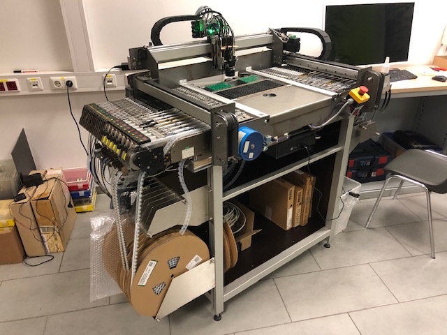
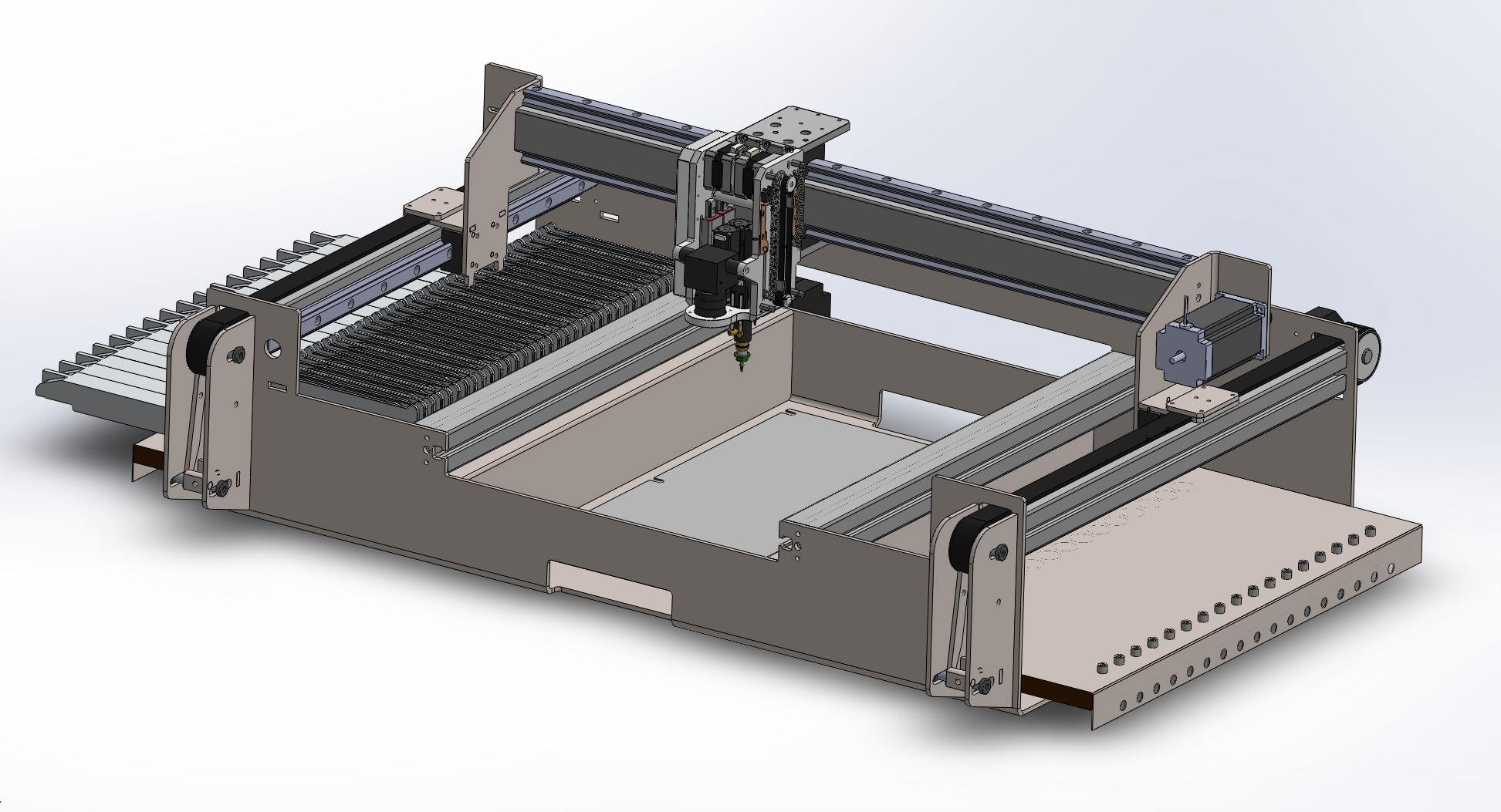
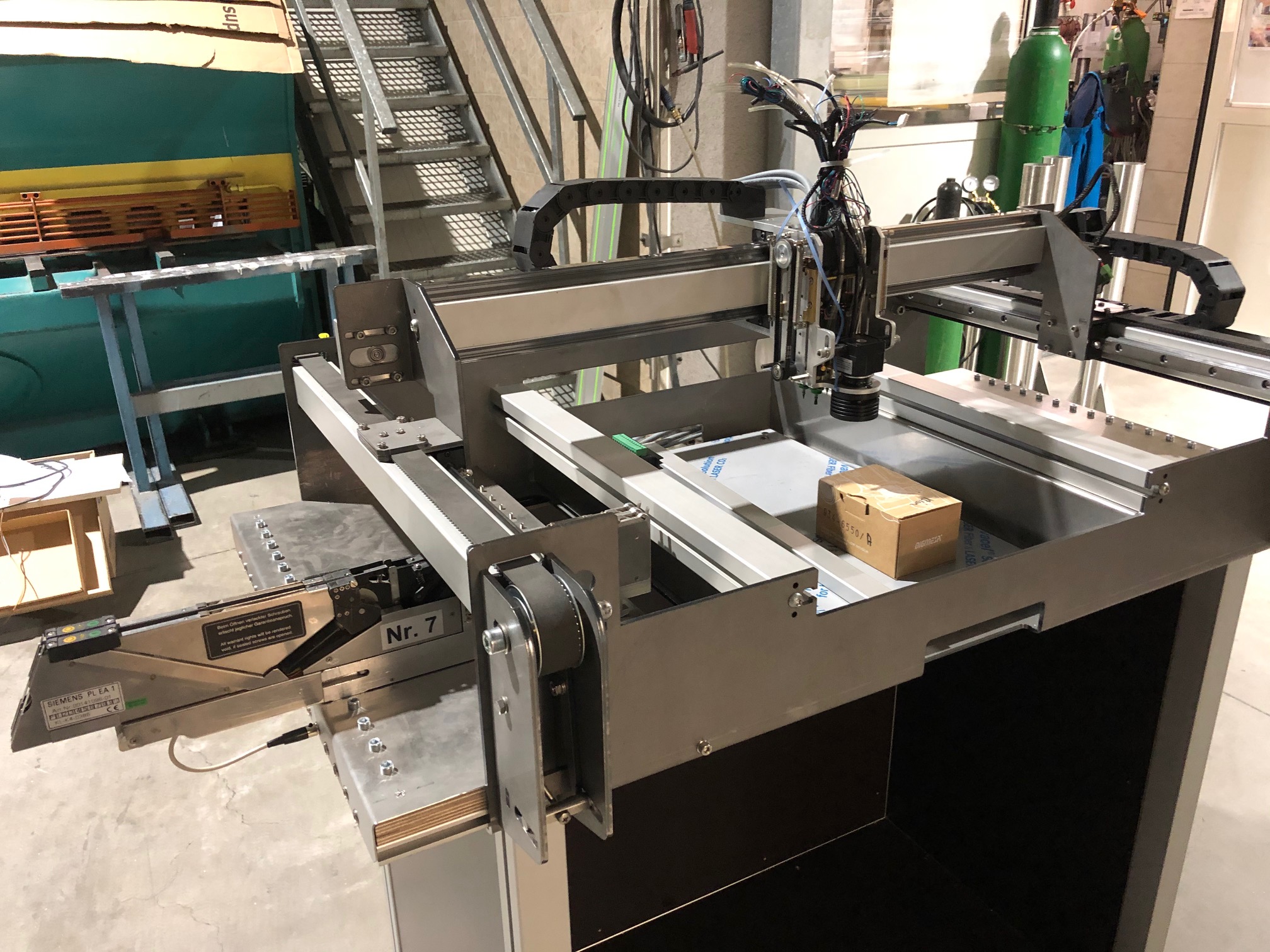
I had planned to build a desktop machine.
Not even close!! I guess I overdid it. In the current expansion stage, the machine already weighs 80 kg ... without feeder, without control, without placement head, ... without almost anything.
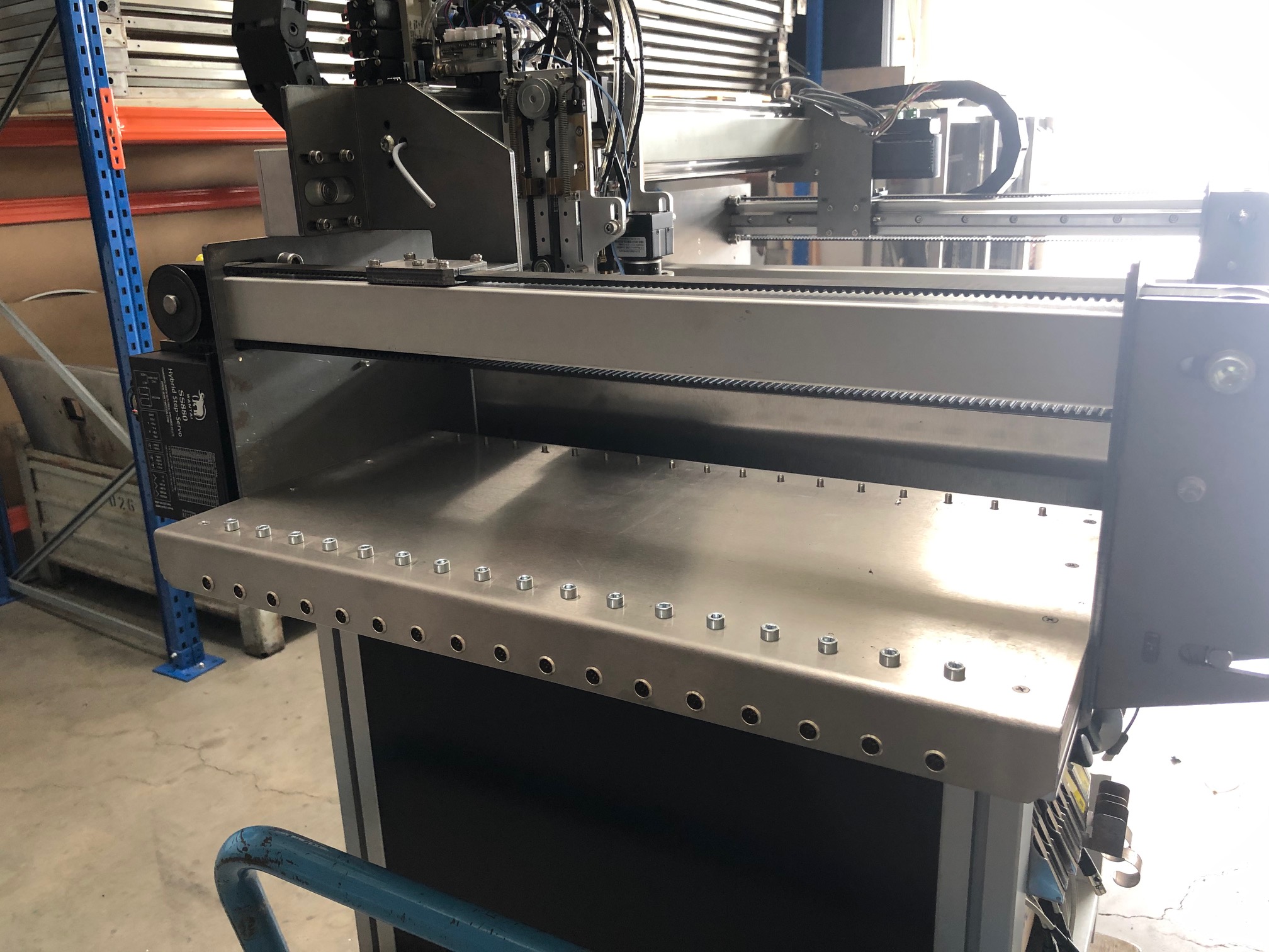
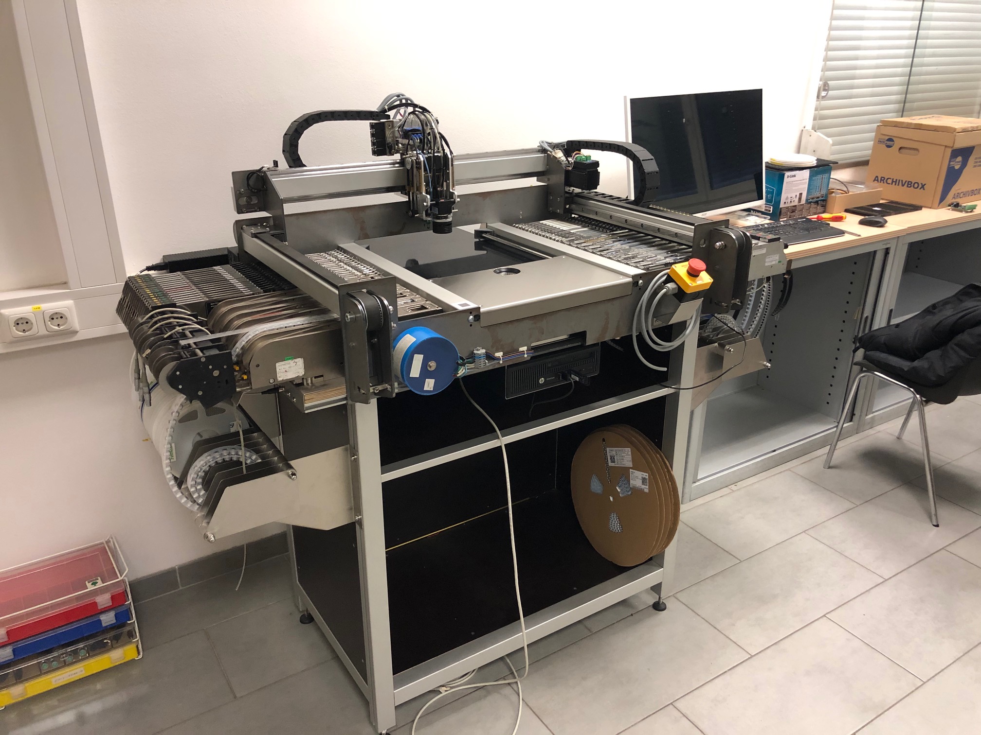
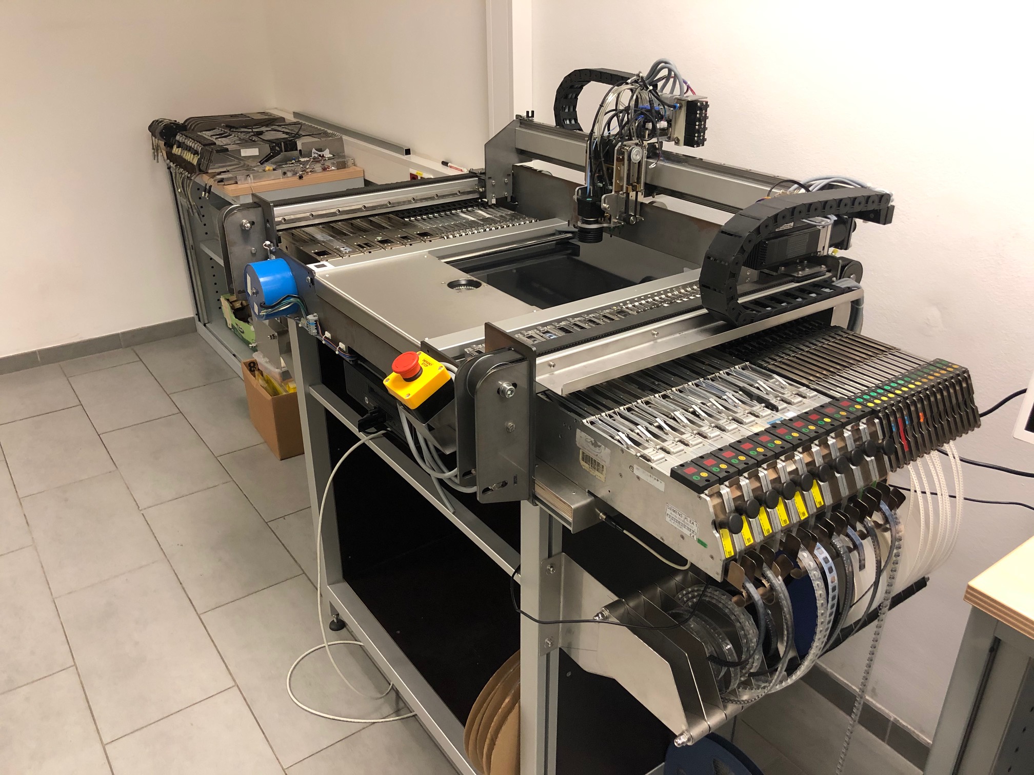
The machine is designed for the Siplace / Schultz feeder and offers space for a total of 34 pieces, e.g. 2x8mm feeder. The active assembly area is 300x500 millimeters. Of course, PickUp positions can also be set up in this area. I designed a 4-way head as the placement head.
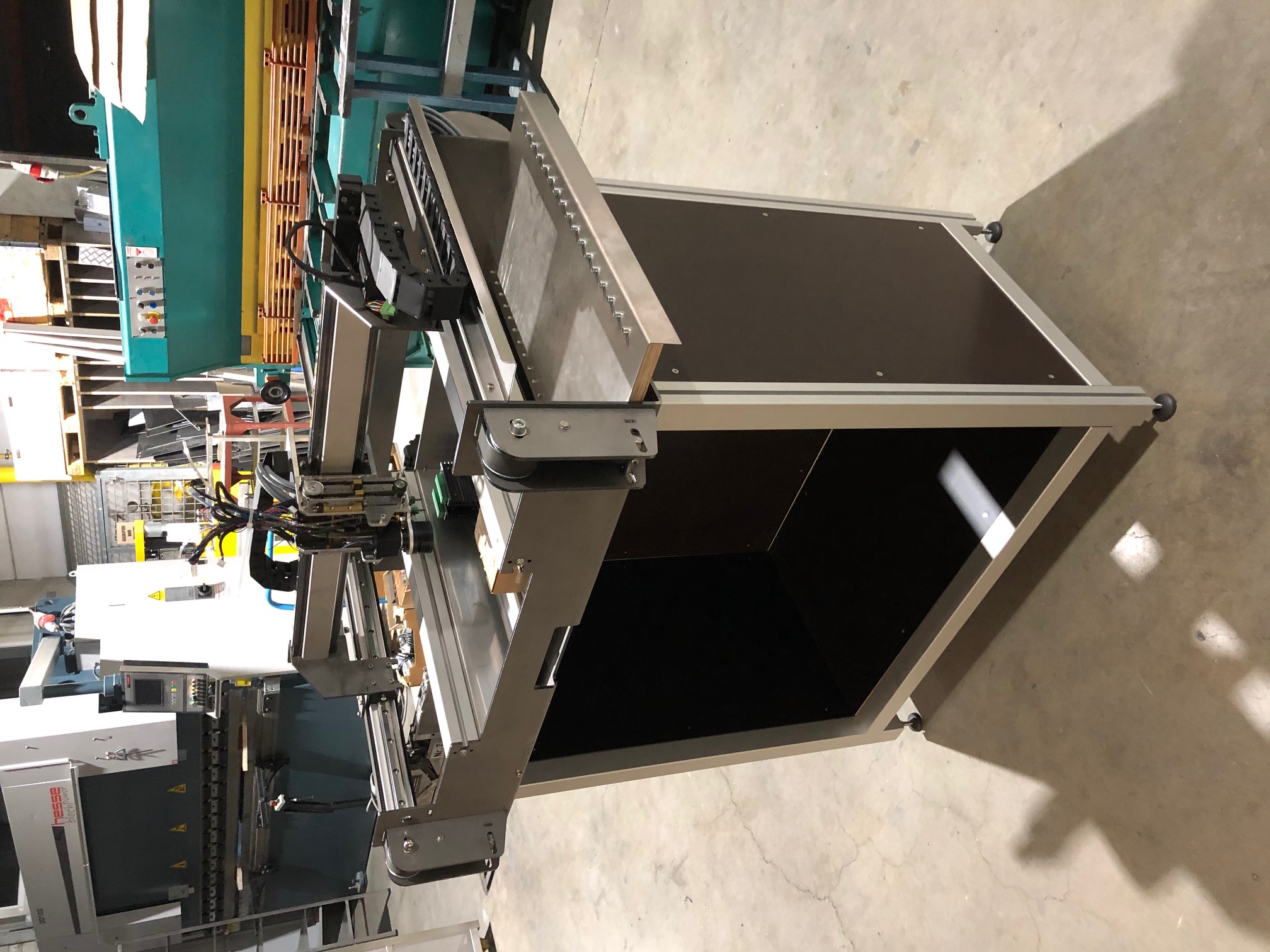
Here is the construction of the machine:


Nick
--
You received this message because you are subscribed to the Google Groups "OpenPnP" group.
To unsubscribe from this group and stop receiving emails from it, send an email to openpnp+u...@googlegroups.com.
To view this discussion on the web visit https://groups.google.com/d/msgid/openpnp/ce82f761-f292-4c59-a8dd-ba3e7f211692n%40googlegroups.com.

chende...@gmail.com

eklun...@gmail.com
Christian...@gmx.at
chende...@gmail.com
eklun...@gmail.com
--Per
Christian...@gmx.at
Am I correct if I assume that you are from France?
Shall I send you the raw material?
Christian...@gmx.at
eklun...@gmail.com
Christian...@gmx.at
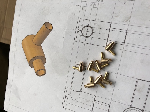
The parts are 8mm thick.
eklun...@gmail.com
Christian...@gmx.at
If it doesn't work, it's of course not a problem;)
Christian...@gmx.at
Christian...@gmx.at
I wrote to several companies and asked for an offer for the aluminum milled parts. The cheapest offer I received was this:
Quadro Head Ground plate: € 156.00 (one needed)
Quadro Head Side Plate: € 192.00 (two needed)
Shipping Europe-wide € 12.90
Anyone interested in the parts ?? I would then order several parts at once.

Clemens Koller
You might want to check if you can get along with laser-cut plates. These could possibly lower your costs because of much lower tooling cost in comparison to milling.
Just my 5 Cents,
Clemens
--
>
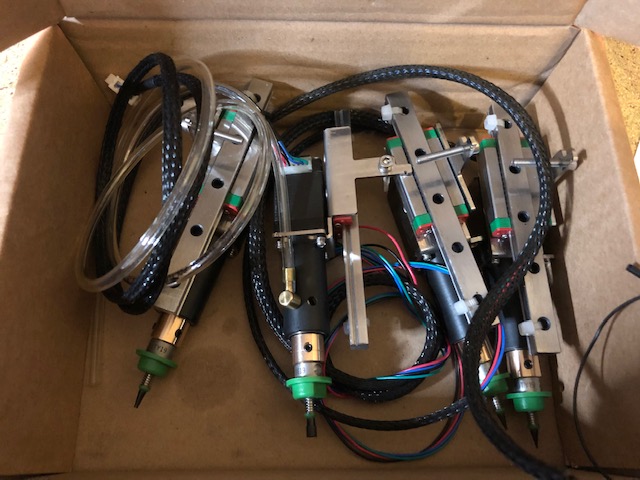
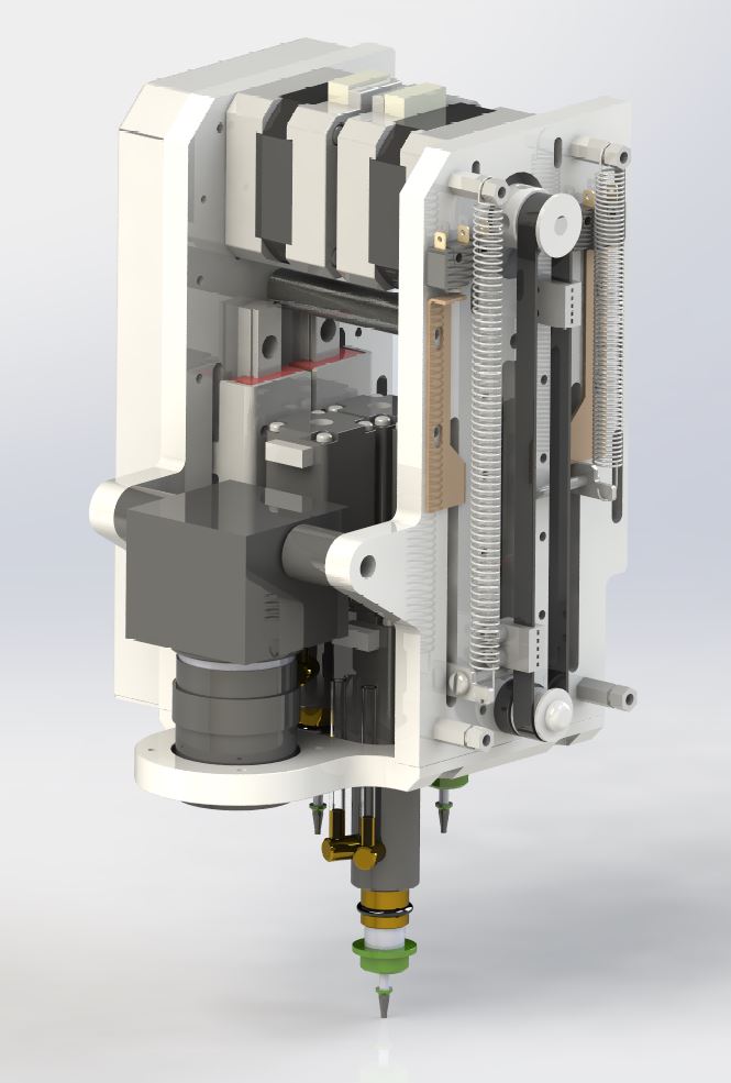
> And here is the construction of the placement head:
>
>
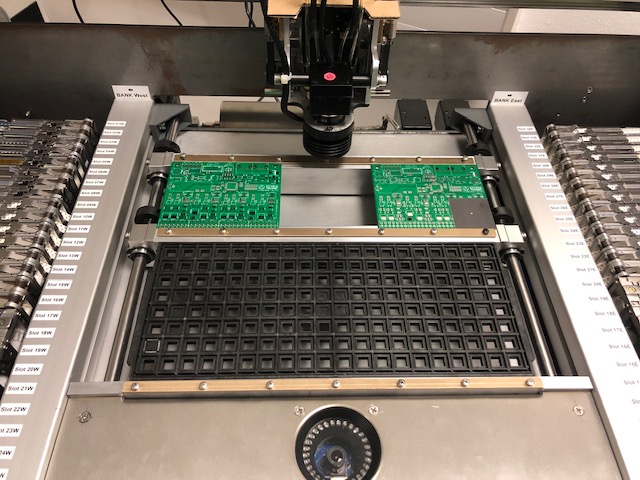
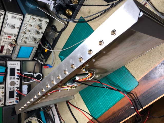
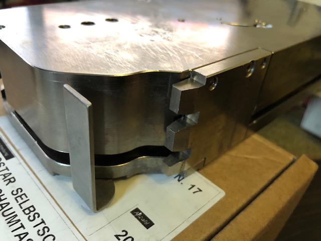
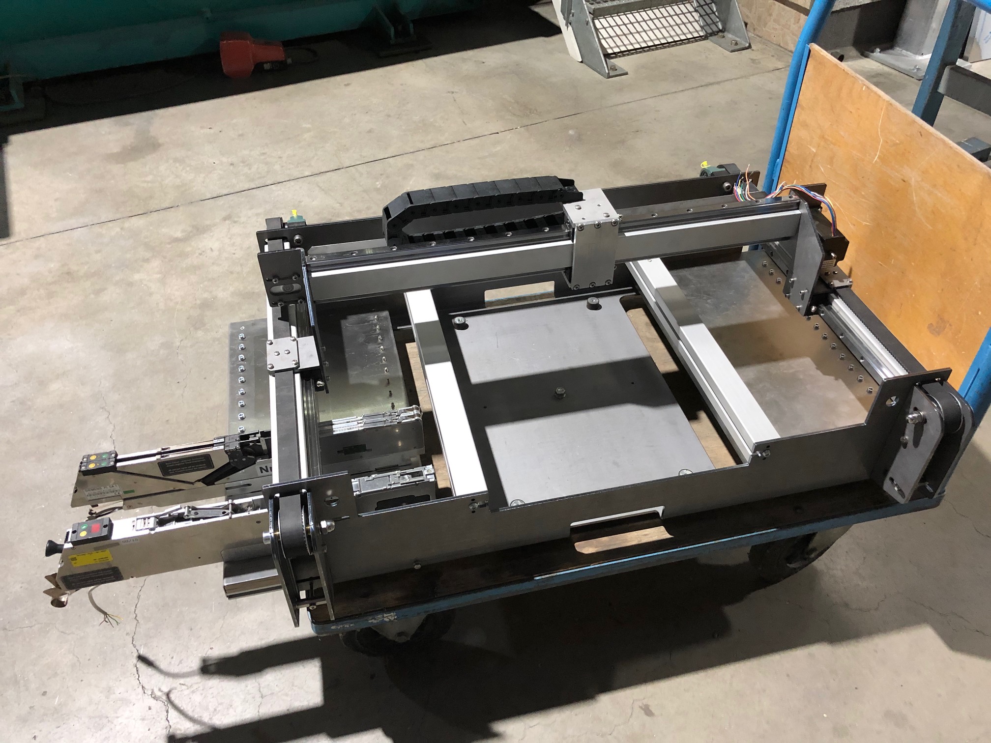
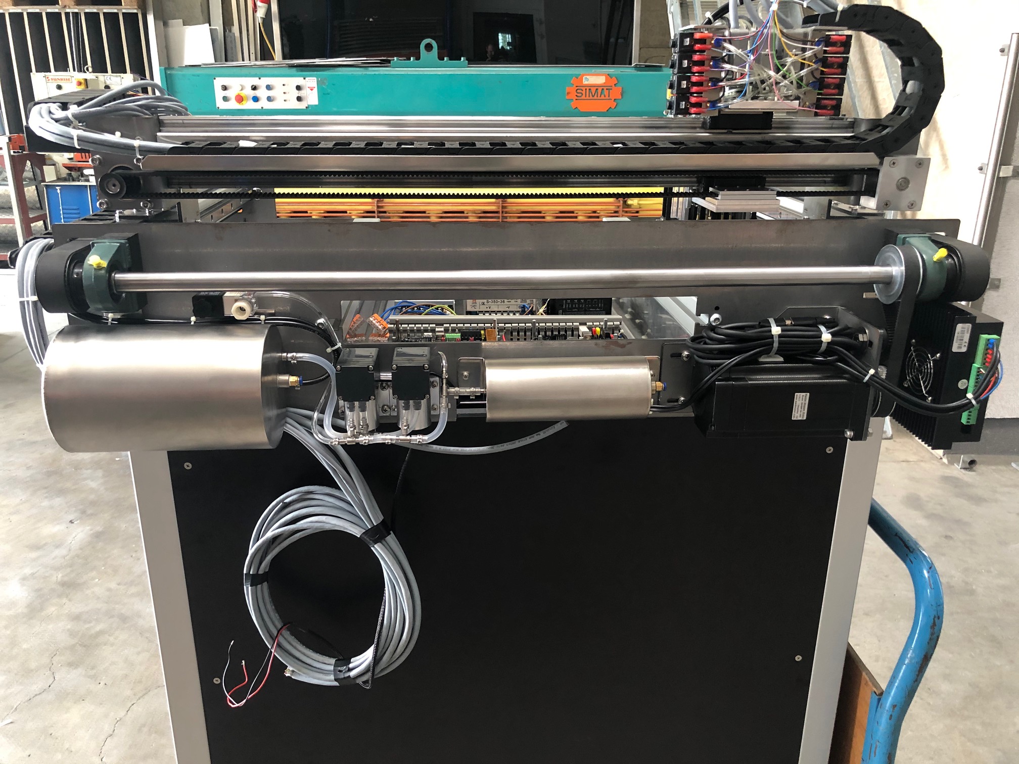
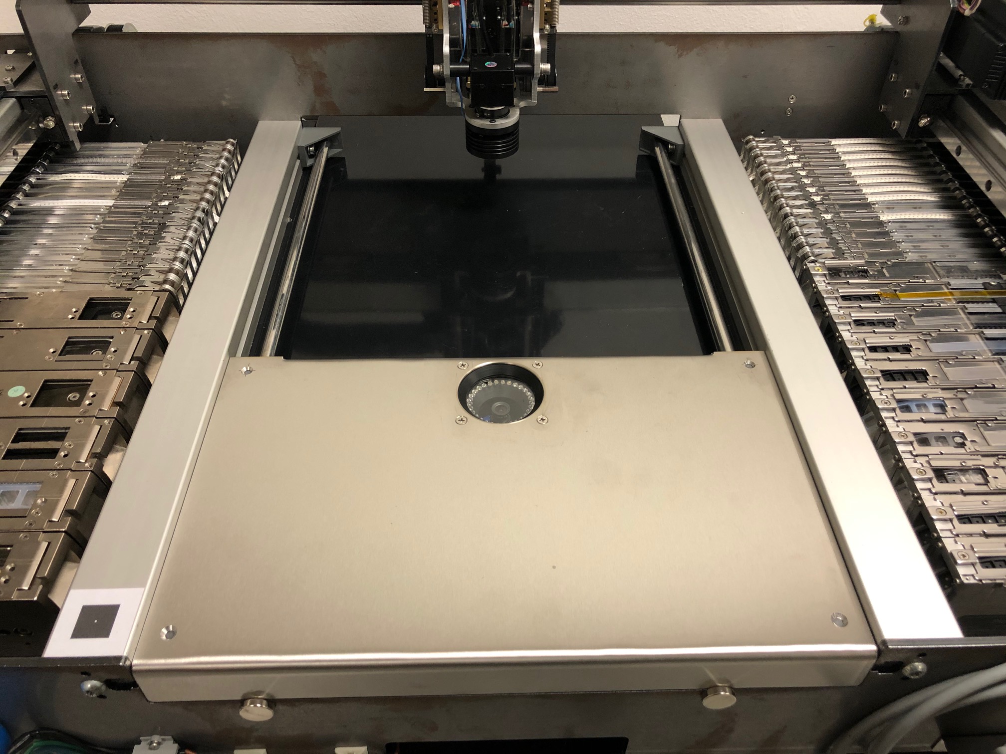
> And here is a photo of the machine showing the current production progress:
>
>
>
> I still have to manufacture all machine parts that are still missing, which unfortunately will still take some time. Mainly because my CNC milling machine was unfortunately struck by lightning and I need to repair it first.
>
> I am always open to discuss suggestions for improvement.
> AND YES, if anyone wants them, I can provide the construction files ;)
>
> By the way, if someone can produce 8mm aluminum milling parts for little money and get it shipped cheaply to Austria, please contact me :-) (I still need the three aluminum plates from the assembly head ... but - as you already know - my milling machine is dead at the moment)
>
> So, hope you like it.
>
> Best regards,
> Christian
>
> --
> You received this message because you are subscribed to the Google Groups "OpenPnP" group.
> To unsubscribe from this group and stop receiving emails from it, send an email to openpnp+u...@googlegroups.com.
> --
> You received this message because you are subscribed to the Google Groups "OpenPnP" group.
> To view this discussion on the web visit https://groups.google.com/d/msgid/openpnp/4c92d2e9-9600-4eb3-8443-ad5e9f8a9891n%40googlegroups.com <https://groups.google.com/d/msgid/openpnp/4c92d2e9-9600-4eb3-8443-ad5e9f8a9891n%40googlegroups.com?utm_medium=email&utm_source=footer>.
Christian...@gmx.at
why haven't I come up with the idea myself?!?!
I try to get a quote for the laser cut parts
I will then tell you whether and how much it is cheaper.

ja...@loveelectronics.co.uk
ja...@loveelectronics.co.uk

Yevhenii Shcherbakov
Christian...@gmx.at

Dave Park
I will not use Steel, it is way to heavy.Just if it is still to expensive i will reduce the thickness of the aluminium plates to 5 mm.I have a company nearby that can laser-cut aluminum plates up to a thickness of 10mm with an accuracy of +/- 0.1mm without problems.Since I don't need an exact fit for the parts, that's perfectly adequate for me. I drew the threaded holes all with a 0.5 mm smaller diameter.I then drill this on the column drill to the core diameter and cut the thread into it myself.I can make the four fitting surfaces on the parts with the manual milling without any problems.So now I hope that laser cutting is significantly cheaper than milling.
Christian...@gmx.at
Clemens Koller
On 31/10/2020 07.46, Yevhenii Shcherbakov wrote:
> Steel - bad idea.
> It will weigh 3 times more. This is extra weight that will affect top speed and acceleration.
> For this product, in terms of strength, 3 mm of aluminum is enough.
add some construction (bents, additional rails) to make your design more stiff.
IMO, a lot of (open source) constructions suffer in oversized everything. A single M4 screw 8.8 steel should be able to hold up to 7kN (~700kg).
> 4KW laser cuts 6mm thick aluminum. This is maximum. One can find waterjet cutting and cut on it. There, the thickness is noticeably greater. But in all these methods there is a drawback: the poor quality of the cut end. If there are precise fit of the parts, you will have to additionally process the surfaces.
Regards,
Clemens
--
On 31/10/2020 07.46, Yevhenii Shcherbakov wrote:
> Steel - bad idea.
> It will weigh 3 times more. This is extra weight that will affect top speed and acceleration.
>
> For this product, in terms of strength, 3 mm of aluminum is enough. 4KW laser cuts 6mm thick aluminum. This is maximum. One can find waterjet cutting and cut on it. There, the thickness is noticeably greater. But in all these methods there is a drawback: the poor quality of the cut end. If there are precise fit of the parts, you will have to additionally process the surfaces.
>
> пятница, 30 октября 2020 г. в 23:44:13 UTC+2, ja...@loveelectronics.co.uk:
>
> I meant to say changing to steel would increase your weight.
>
> On Friday, October 30, 2020 at 9:43:48 PM UTC ja...@loveelectronics.co.uk wrote:
>
> FYI If your getting this laser cut, 8mm is on the very thick side for Aluminium, it doesn't laser very efficiently. Changing to steel would be cheaper, but increase your cost, if you reduce the thickness of the parts down to maybe 4mm this would be more effective, but then if you've reduced it to 4mm then the milling would be cheaper, as your 3mm slots are only 1.5D instead of 3xD.
>
> Just some thoughts from a machininst.
>
> On Friday, October 30, 2020 at 8:41:54 PM UTC Christian...@gmx.at wrote:
>
Yevhenii Shcherbakov
>add some construction (bents, additional rails) to make your design more stiff.
>IMO, a lot of (open source) constructions suffer in oversized everything. A single M4 screw 8.8 steel should be able to hold up to 7kN (~700kg).
Christian...@gmx.at
ja...@loveelectronics.co.uk
Christian...@gmx.at

mike....@gmail.com

betzt...@gmail.com
Christian...@gmx.at
Is there some other reason I should build the plate stronger? Have I missed something important?
Christian...@gmx.at
Christian...@gmx.at
mike....@gmail.com
Christian...@gmx.at
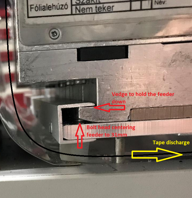
In the beginning I was looking for a way to hold down all feeders in the same way.
I use 2x8mm, 12 / 16mm and 24 / 32mm. All three types of feeders use a different form of assembly.
mike....@gmail.com
Christian...@gmx.at

chende...@gmail.com
Christian...@gmx.at
Sorry if I caused confusion.
All right, one by one:
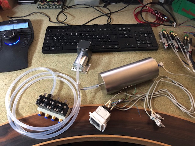
5.) The air pressure is divided and controlled in the same way.

ma...@makr.zone
Hi Christian
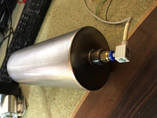
> this tank is also controlled by an air pressure sensor, which opens the tank when the pressure exceeds, for example, 200 mbar in order to avoid a loss of performance of the pump
So you run the pumps all the time?
Why not run them on a hysteresis to keep the tank
pressurized to a certain level?
https://makr.zone/vacuum-sensor/192/
_Mark
--
You received this message because you are subscribed to the Google Groups "OpenPnP" group.
To unsubscribe from this group and stop receiving emails from it, send an email to openpnp+u...@googlegroups.com.
To view this discussion on the web visit https://groups.google.com/d/msgid/openpnp/5932dca5-8d69-4f46-97b1-a9946dff970bn%40googlegroups.com.
ma...@makr.zone
> I made some tests with different juki nozzles and I found that for large nozzles, vacuum difference is large and vacuum level with open circuit is quite close to 0, but with small nozzles there is significant vacuum level present even with the part off, that's because of the flow restriction induced by the small channel of the nozzle. Iirc, around 400mbar with a 501 nozzle and no part attached.
Have you found a solution for that problem?
I tried to improve the OpenPnP vacuum system with relative
measurements etc. but while this greatly improved sensing for the
other nozzle tips, even these enhancements did not fix
the problem for the finest nozzle tip (0402). There is no
conclusive threshold that has neither false positives nor false
negatives:
https://makr.zone/openpnp-advanced-vacuum-sensing-part-on-part-off-detect/421/
I guess for that nozzle tip one would have to build a switchable
flow restriction behind the vacuum sensor.
_Mark
--
You received this message because you are subscribed to the Google Groups "OpenPnP" group.
To unsubscribe from this group and stop receiving emails from it, send an email to openpnp+u...@googlegroups.com.
To view this discussion on the web visit https://groups.google.com/d/msgid/openpnp/a4c0ab09-298a-4059-9fea-6313ffd2a47dn%40googlegroups.com.
chende...@gmail.com
Christian...@gmx.at
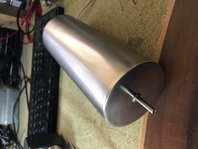
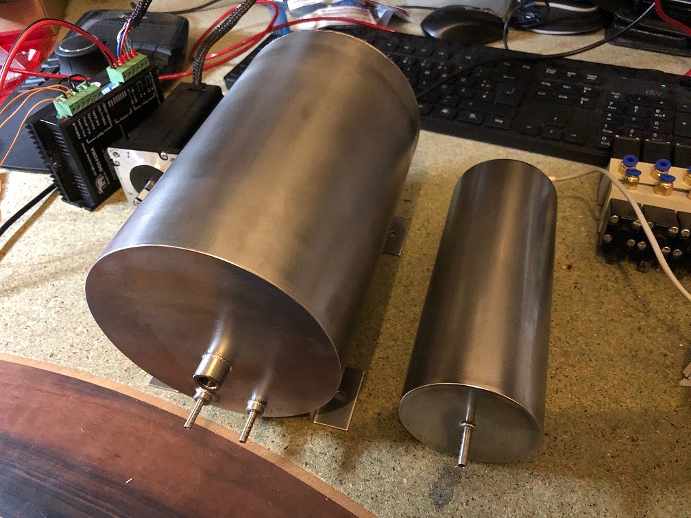
One of the two pumps fills an air pressure tank at the same time.

Harjit Singh
To view this discussion on the web visit https://groups.google.com/d/msgid/openpnp/af96f04b-0768-4b93-8524-67e0ce674883n%40googlegroups.com.
Christian...@gmx.at
That should be ready in a couple of days. I still have to wait for the laser parts.
I also need to do some tests as a basis for the comments
Christian...@gmx.at
Harjit Singh
To view this discussion on the web visit https://groups.google.com/d/msgid/openpnp/4b17ecc9-aaa4-471f-b909-e3e04e18c39an%40googlegroups.com.
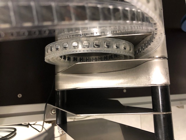
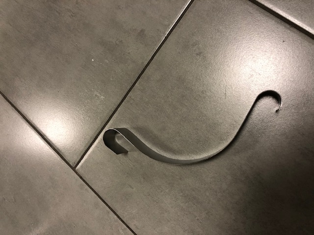
Christian...@gmx.at
That’s it. Not a big deal
Unfortunately I didn't take many pictures, I only have two more:
Christian...@gmx.at
Due to too much work and even more lack of time, I couldn't come here to share the progress of my PnP Machine.
For the same reason, my machine is taking a lot longer to complete than I had hoped.

Jesse Lackey
fiddle and make.
J
> You received this message because you are subscribed to the Google
> Groups "OpenPnP" group.
> To unsubscribe from this group and stop receiving emails from it, send
> an email to openpnp+u...@googlegroups.com
> <https://groups.google.com/d/msgid/openpnp/7097d9d1-5f34-464e-99e8-e3bd8e14ca5dn%40googlegroups.com?utm_medium=email&utm_source=footer>.
Christian...@gmx.at

Ian Arkver
Ian

Dennis Deyen
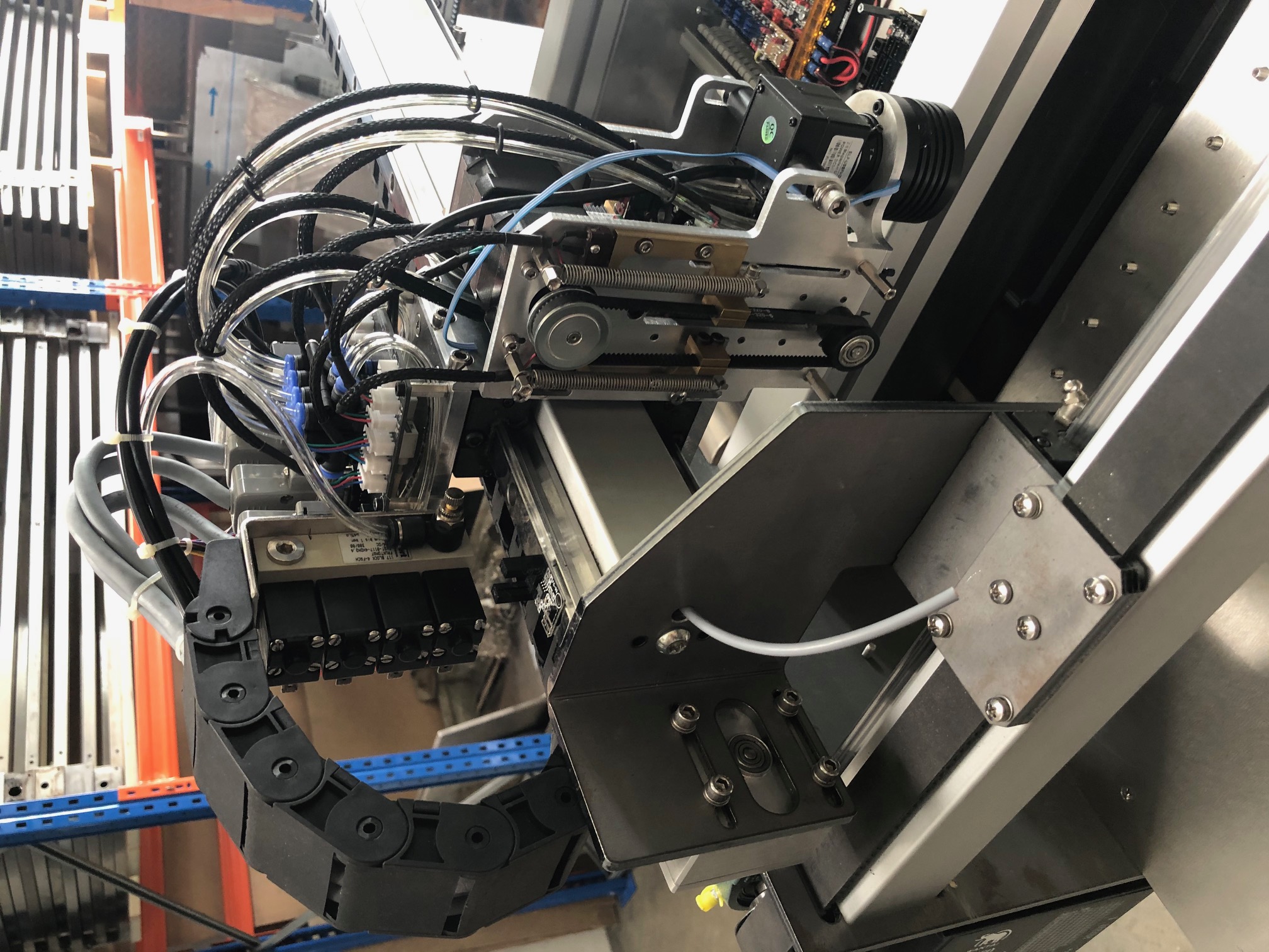
And here is the construction of the placement head:
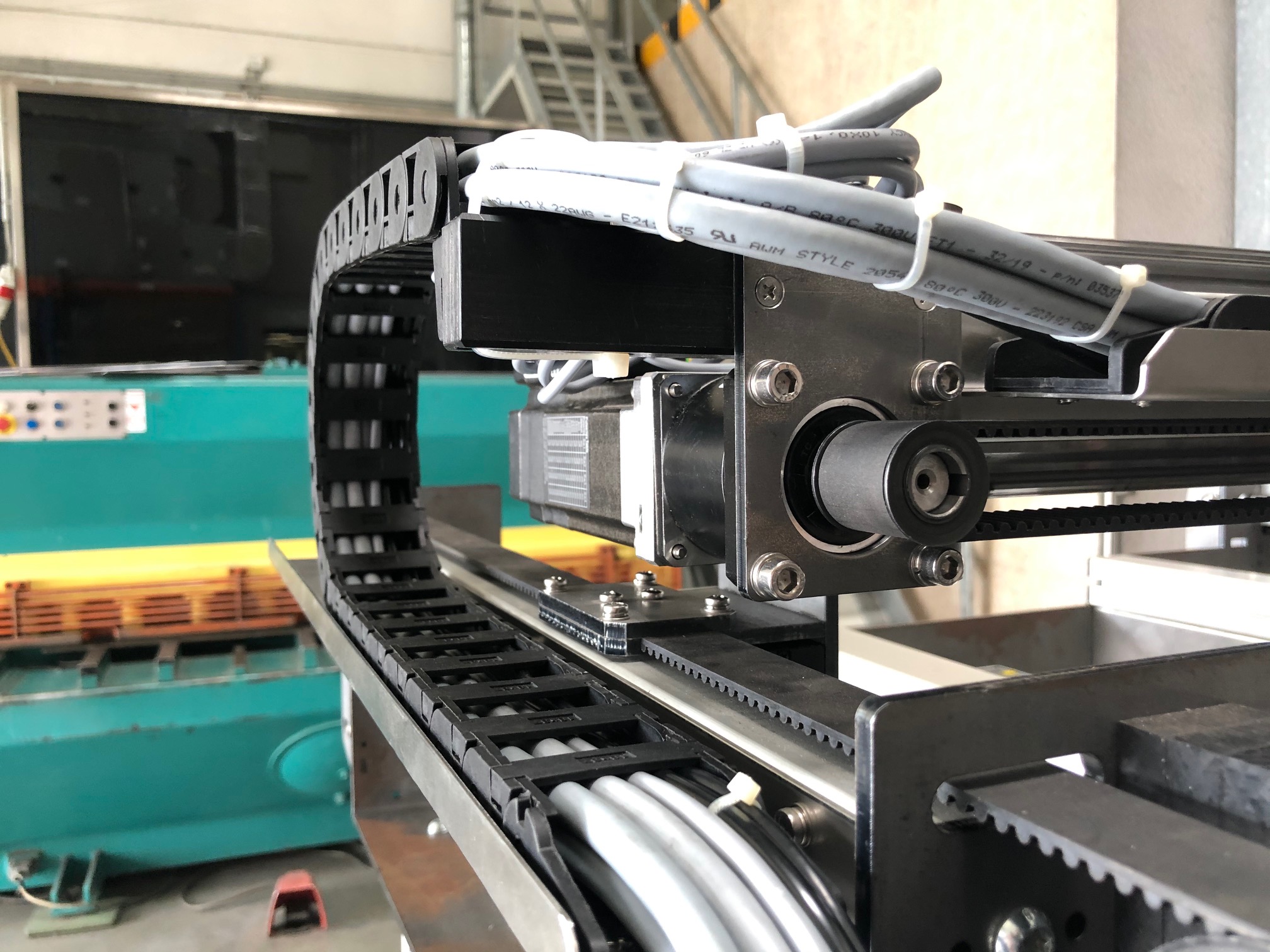
And here is a photo of the machine showing the current production progress:
I still have to manufacture all machine parts that are still missing, which unfortunately will still take some time. Mainly because my CNC milling machine was unfortunately struck by lightning and I need to repair it first.I am always open to discuss suggestions for improvement.AND YES, if anyone wants them, I can provide the construction files ;)By the way, if someone can produce 8mm aluminum milling parts for little money and get it shipped cheaply to Austria, please contact me :-) (I still need the three aluminum plates from the assembly head ... but - as you already know - my milling machine is dead at the moment)So, hope you like it.Best regards,Christian
--
You received this message because you are subscribed to the Google Groups "OpenPnP" group.
To unsubscribe from this group and stop receiving emails from it, send an email to openpnp+u...@googlegroups.com.
To view this discussion on the web visit https://groups.google.com/d/msgid/openpnp/ce82f761-f292-4c59-a8dd-ba3e7f211692n%40googlegroups.com.
Christian...@gmx.at
In the next few days I will then take care of other problems:
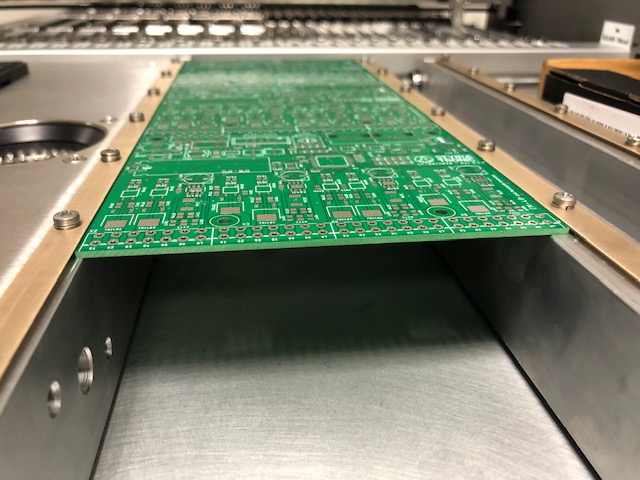
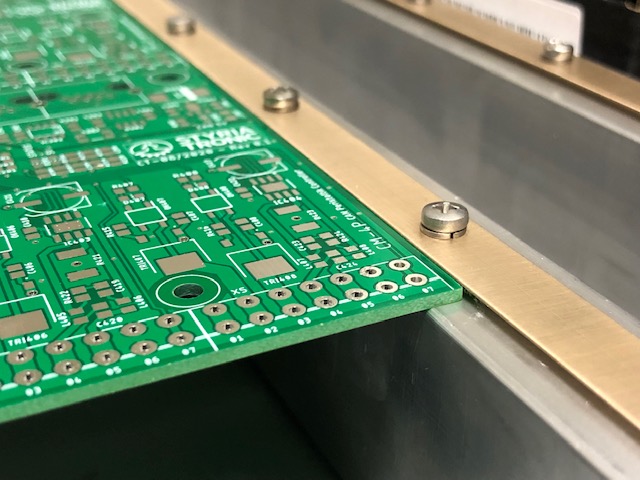
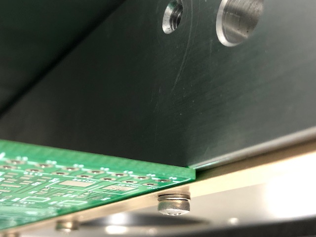
3.) I still have to design reliable board holders.
4.) I still have to think about the best way to connect the emergency stop switch - any ideas??
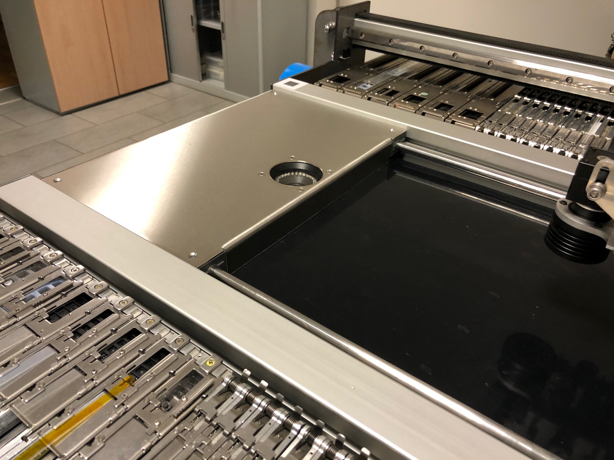
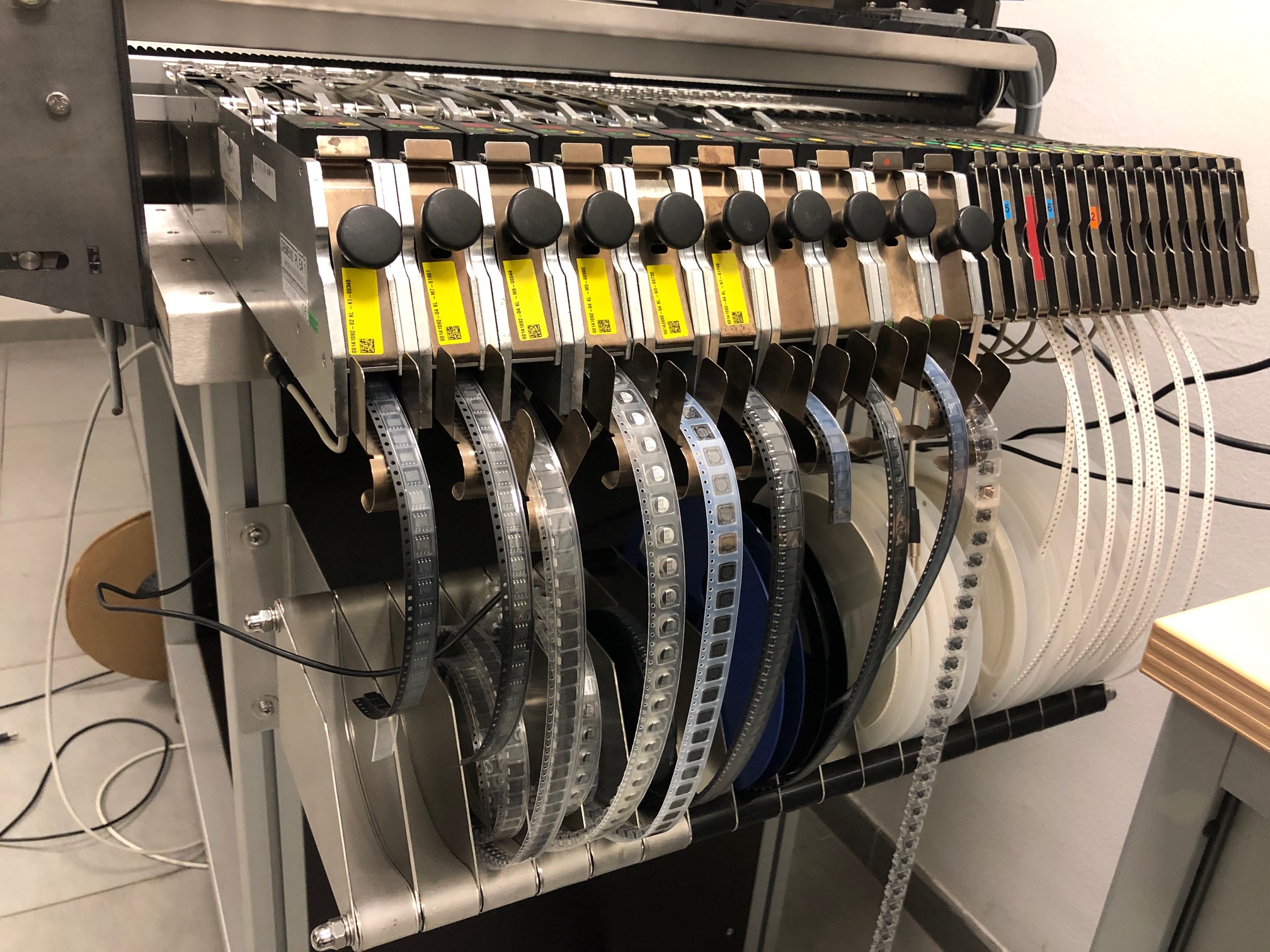
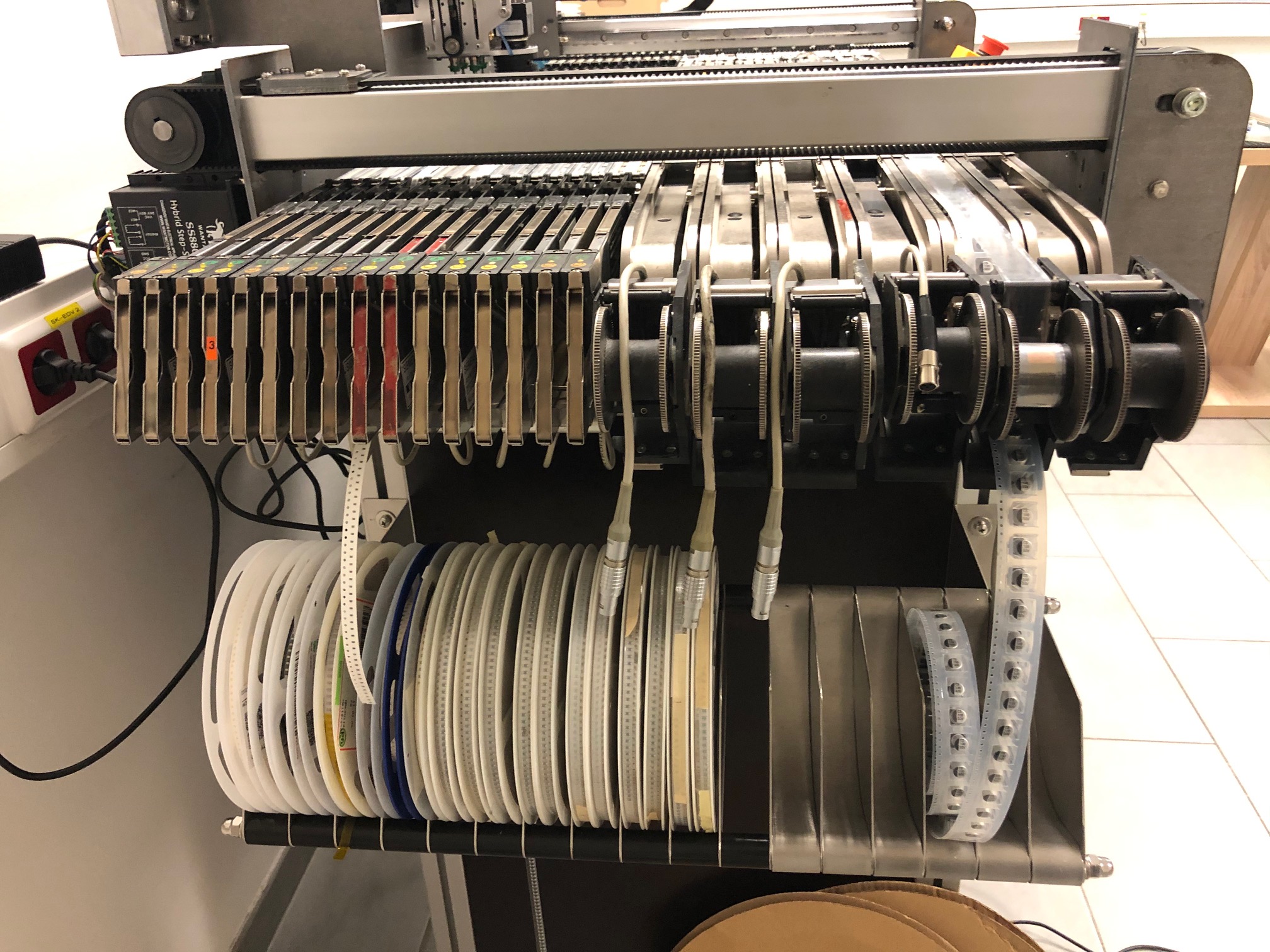
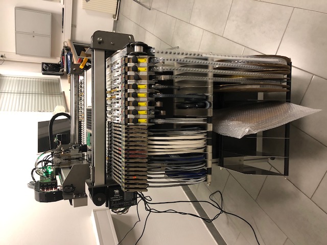
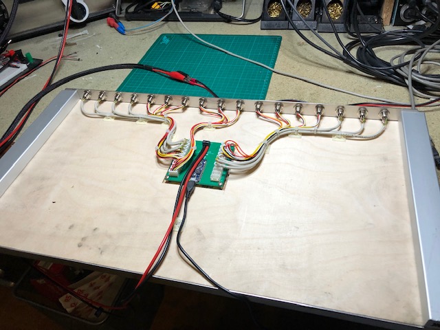
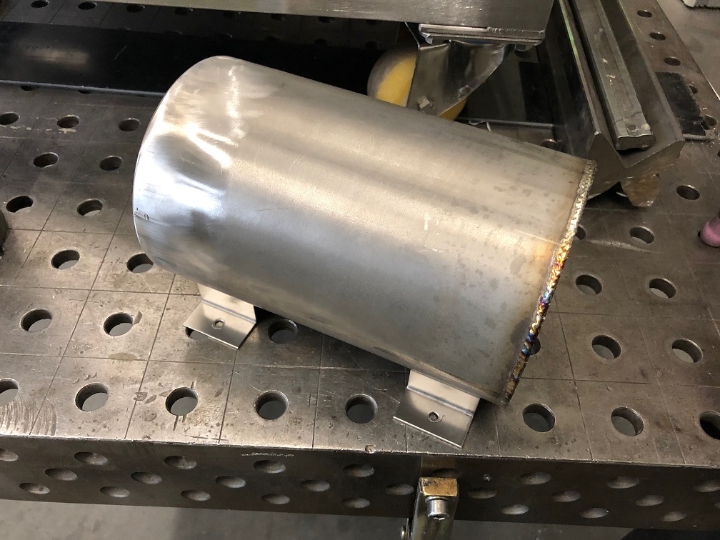
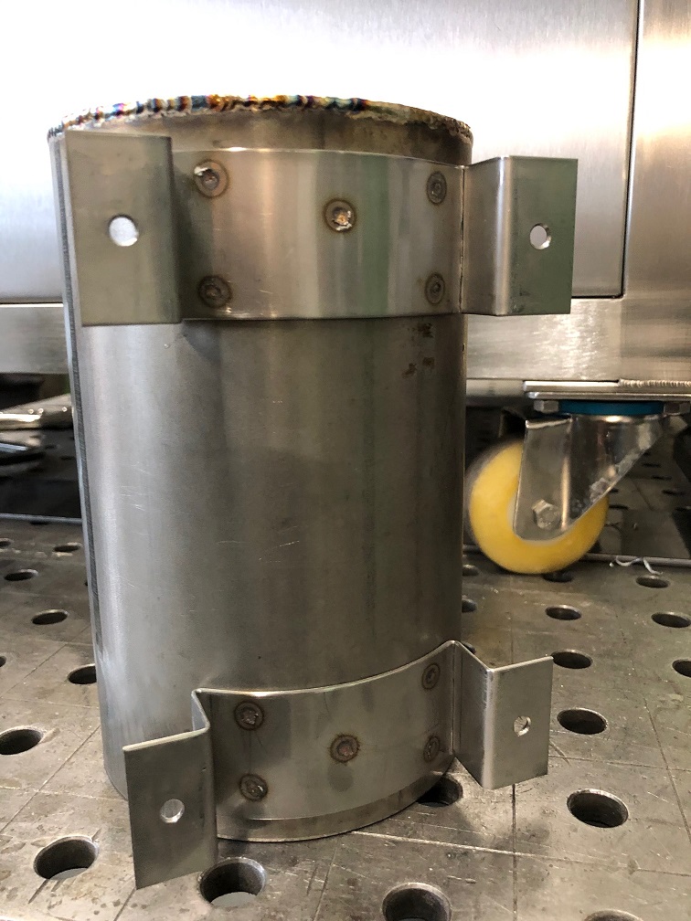
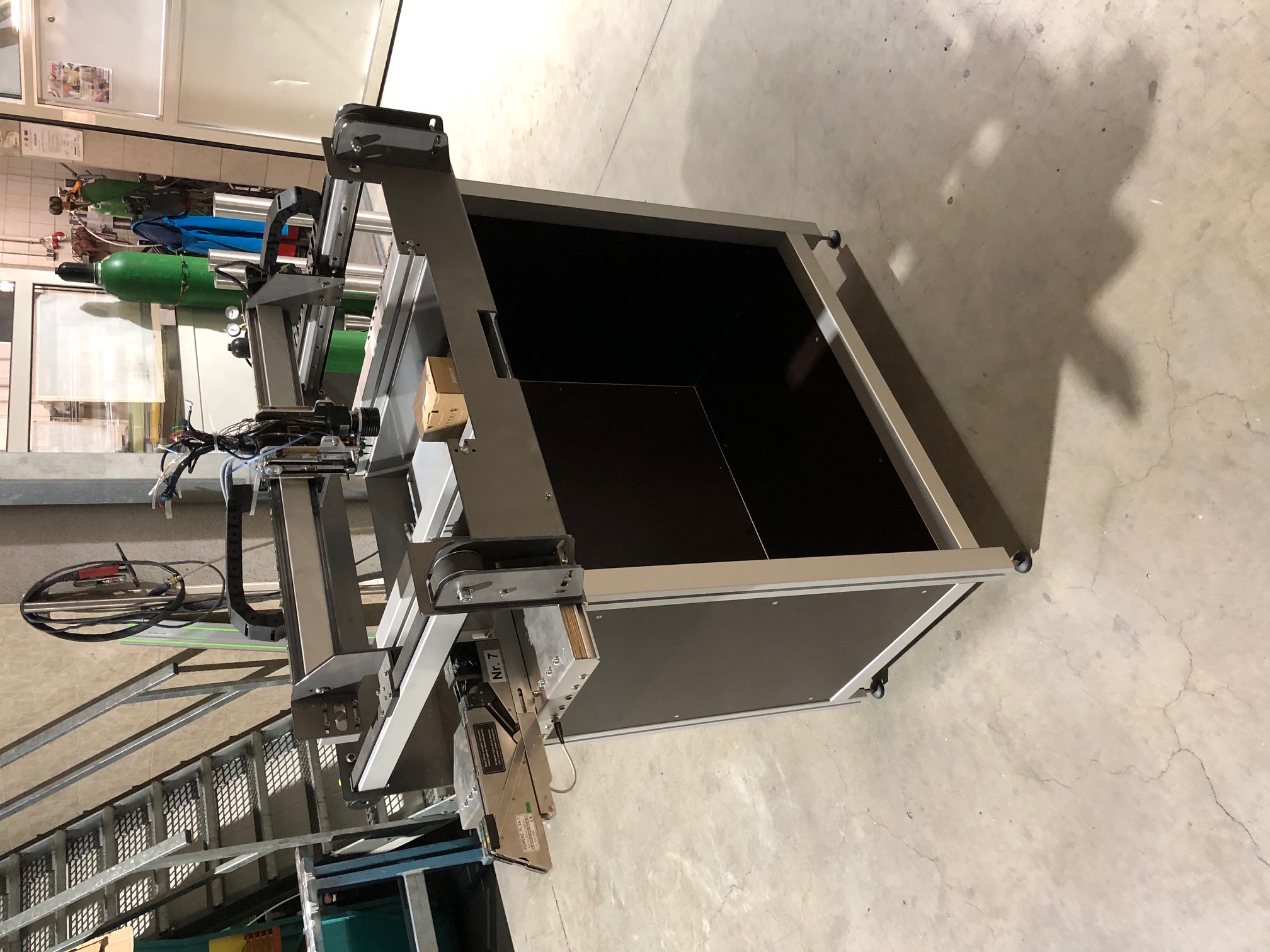
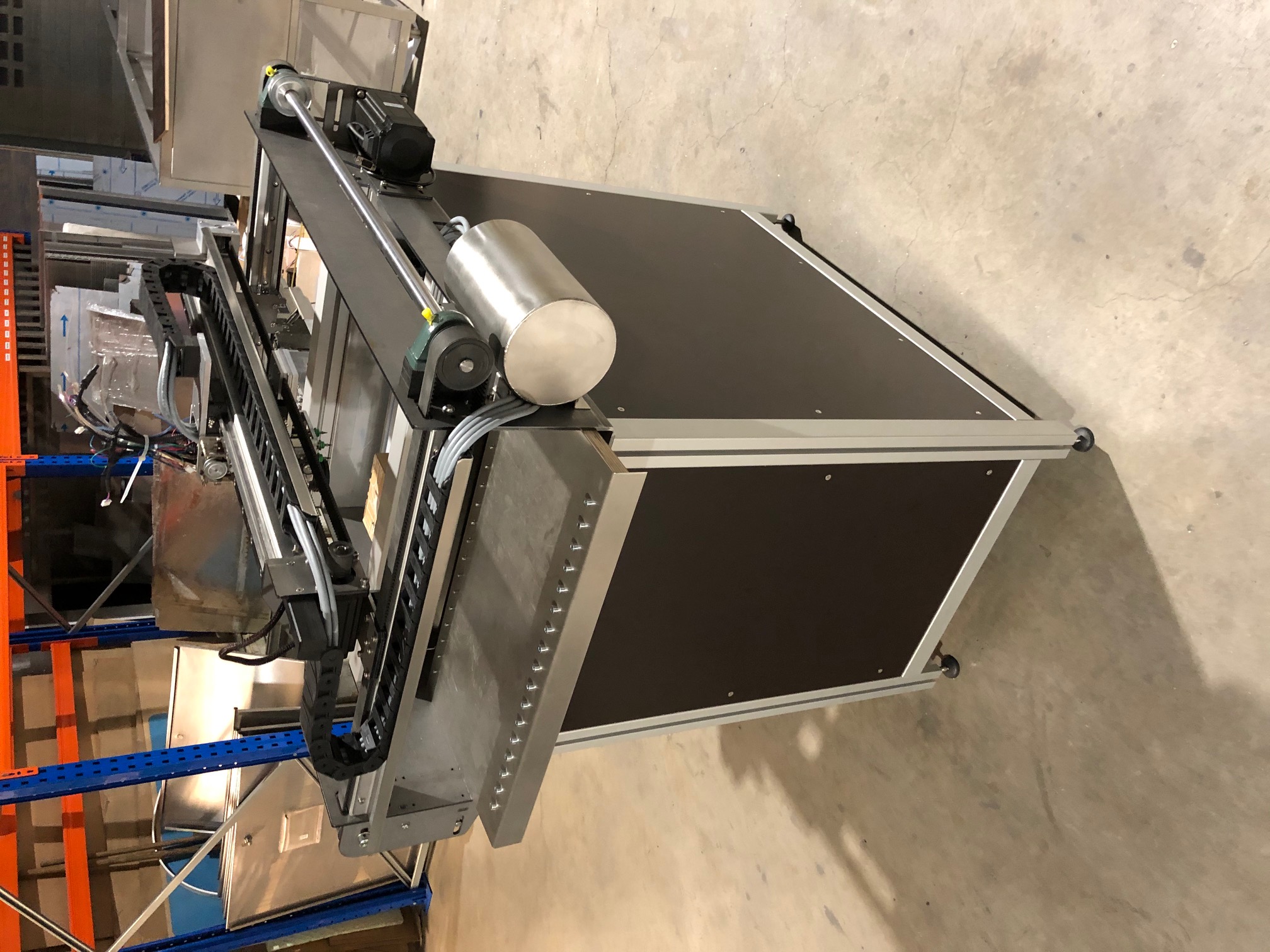
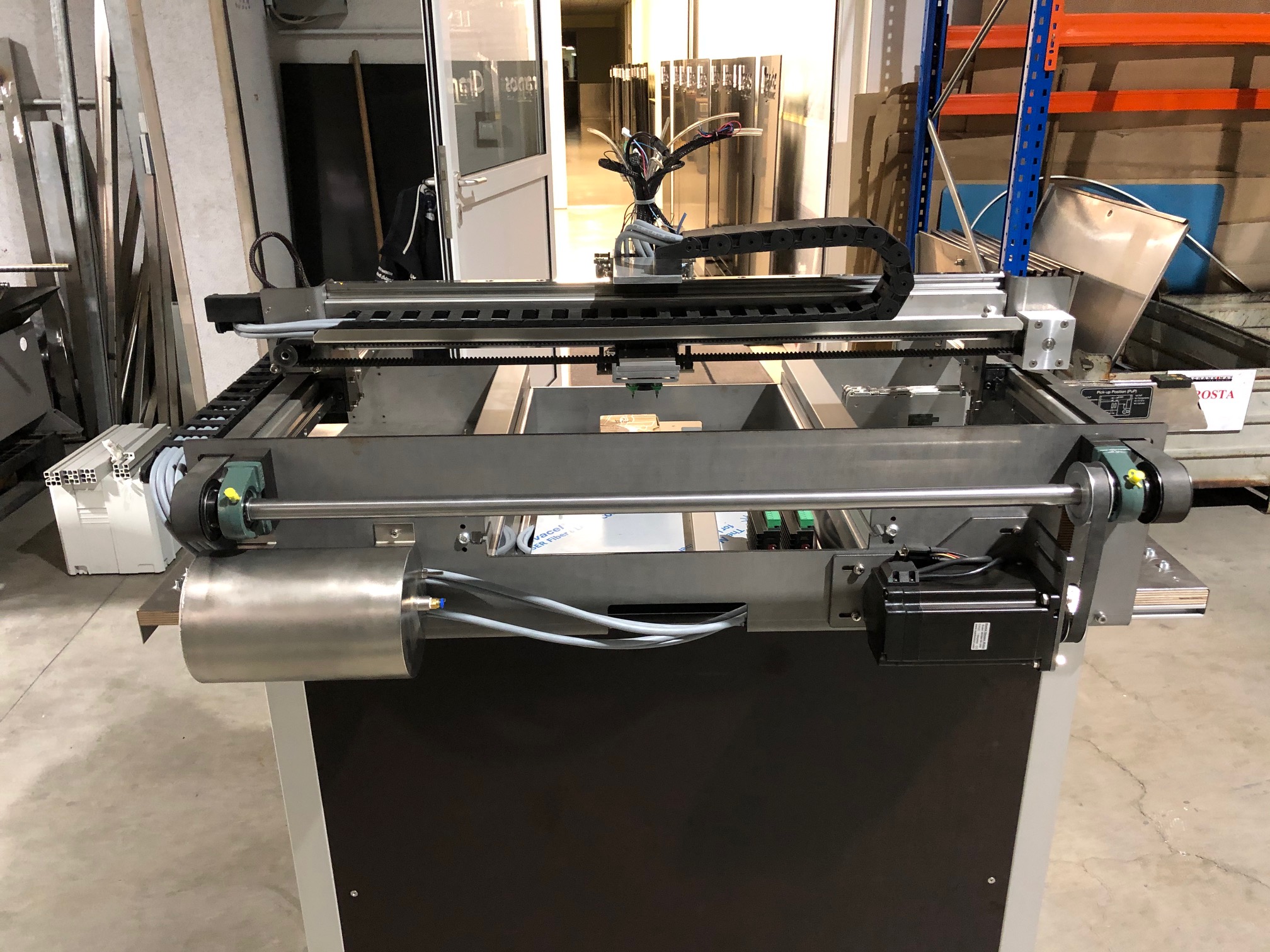
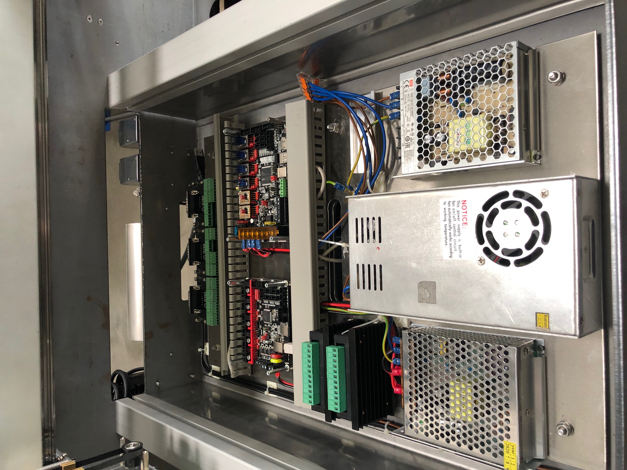
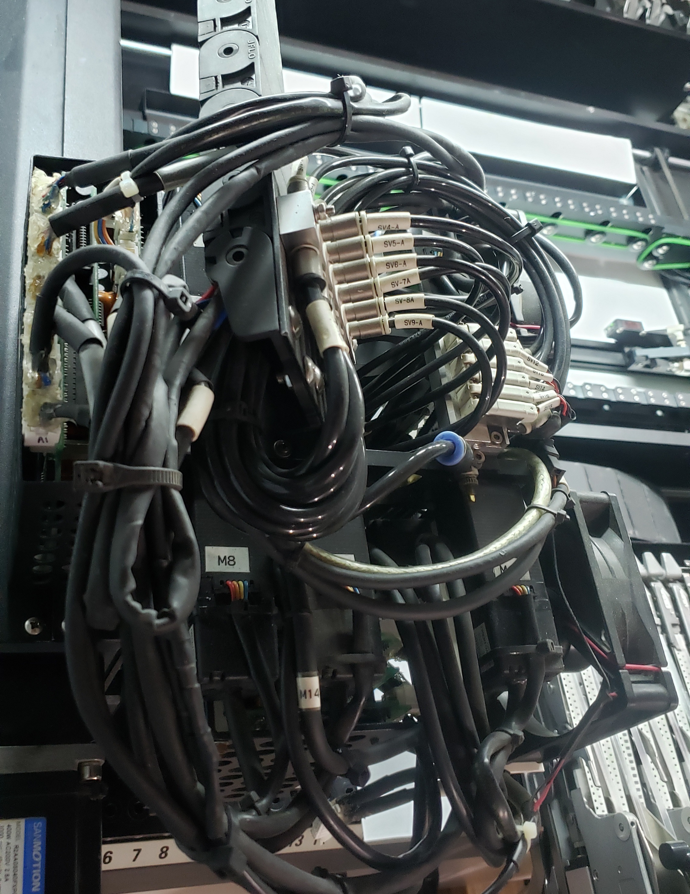
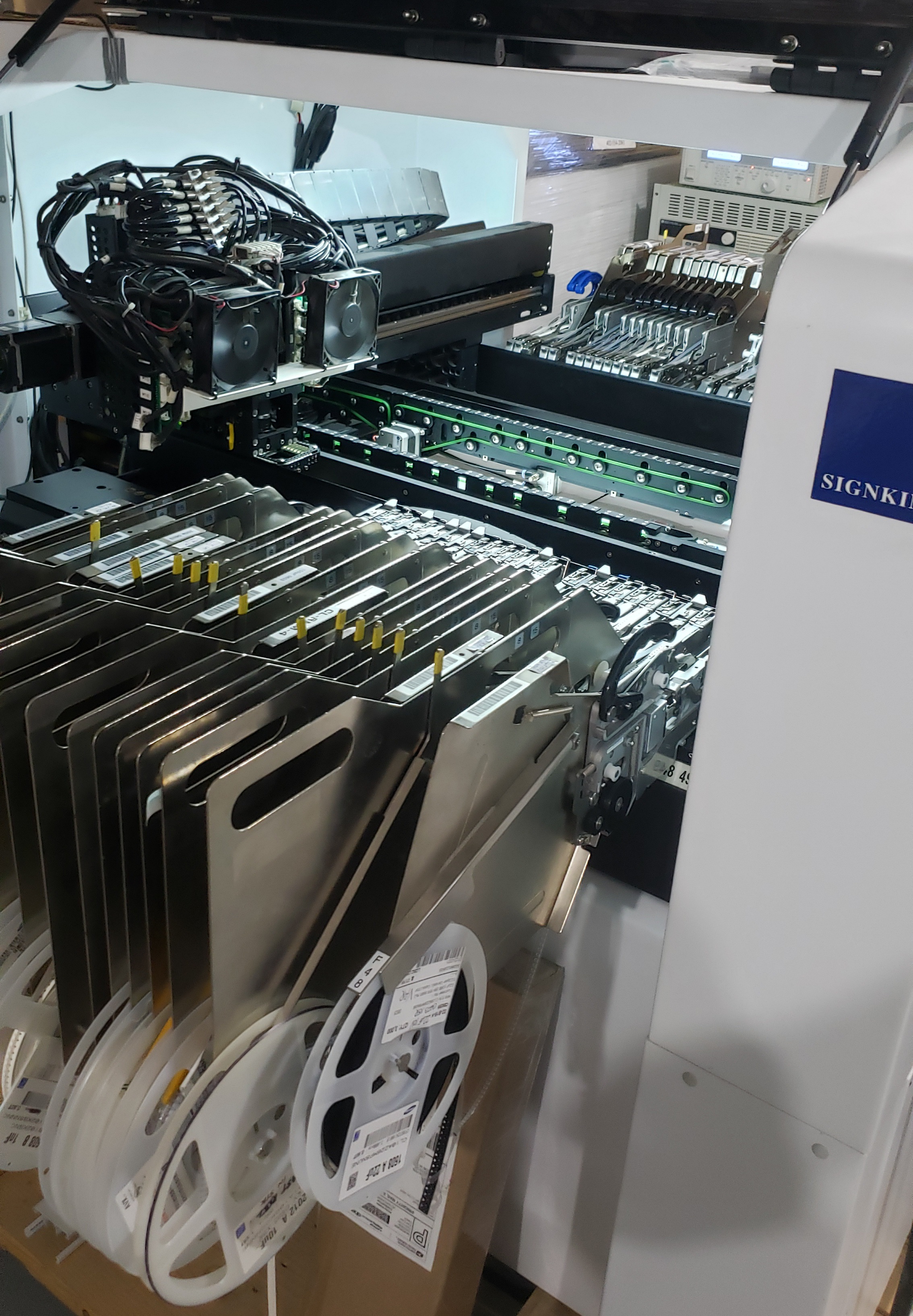
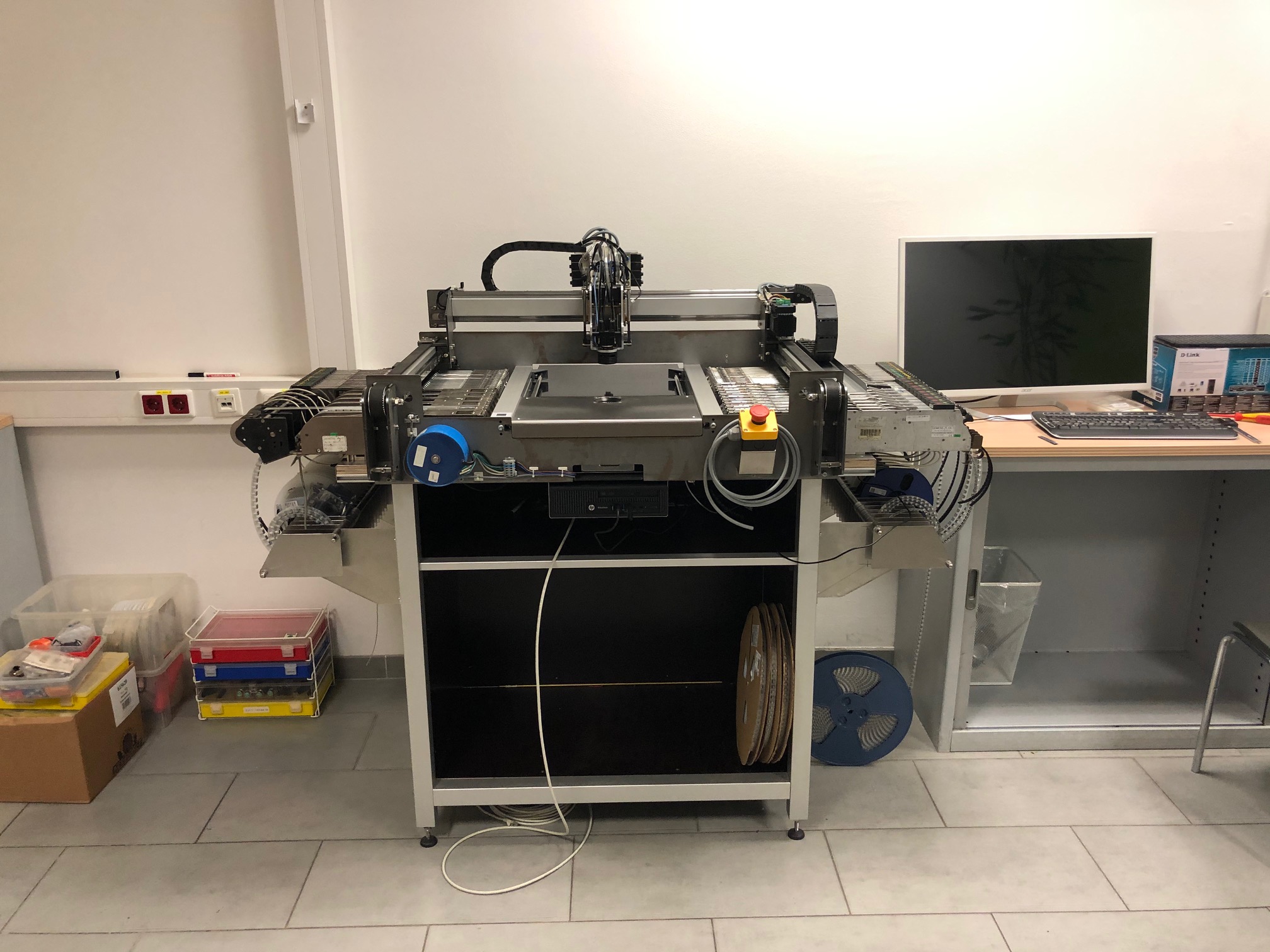 I took a few pictures of my machine again. This is what it looks like now:
Mike Menci
Christian...@gmx.at
I noticed the mistake like this:
First movement:
Camera over pick up position of any feeder -> move to the nozzle over the pick up position and then back to the camera over the pick up position.
Second movement:
Camera over pick up position of the same feeder -> move the head to the maintenance position (Y max, X center) and then back to camera over pick up position.
I know it really looks like a backlash problem, but there is no measurable mechanical backlash in the system.
Mike Menci
Ad.2) I still face communication issues - when setting up Schultz feeders in OpenPnP, but after I start a Job / PnP and Feeders work (???!!)
Mike Menci
Christian...@gmx.at
Christian...@gmx.at
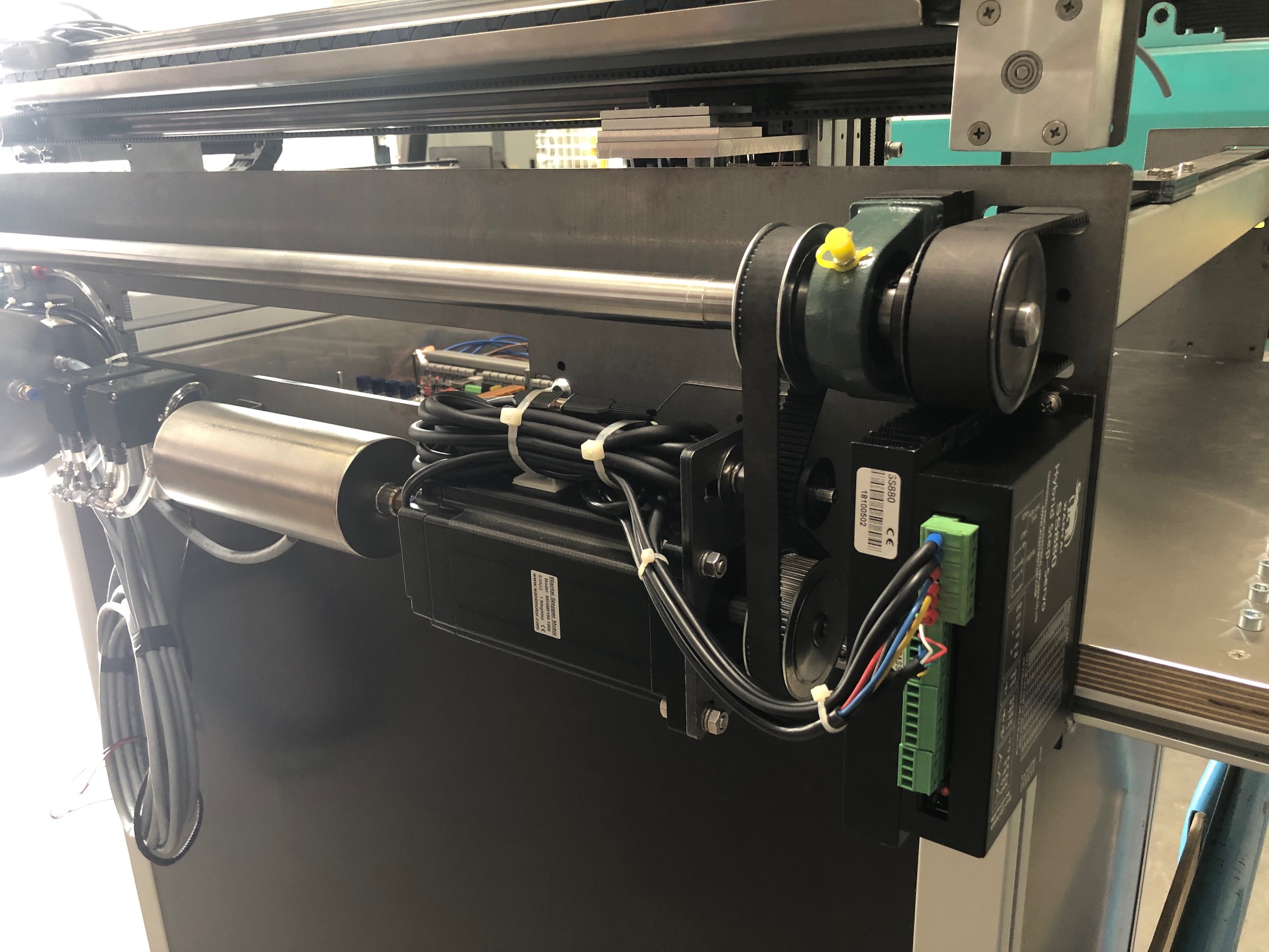
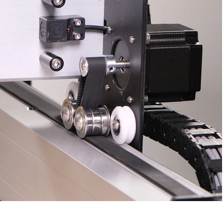
I have now done some tests and have come to the conclusion that the backlash already begins on the engine.
I will now replace the motor (closed loop stepper) with a servo.
Mike Menci
***************************Disclaimer***************************
The contents of this e-mail and any file transmitted with it are confidential and intended solely for the individual or entity to whom they are addressed. The content may also contain legal, professional or other privileged information. If you received this e-mail in error, please destroy it immediately. You should not copy or use it for any purpose nor disclose its contents to any other person. The views stated herein do not necessarily represent the view of the Company.
Please ensure you have adequate virus protection before you open or detach any documents from this transmission. We do not accept any liability for viruses!
On 16 Jan 2022, at 12.22, Christian...@gmx.at <Christian...@gmx.at> wrote:
To view this discussion on the web visit https://groups.google.com/d/msgid/openpnp/2a9e99a3-935c-4ade-b182-99899db51f28n%40googlegroups.com.
Christian...@gmx.at
Mike Menci
***************************Disclaimer***************************
The contents of this e-mail and any file transmitted with it are confidential and intended solely for the individual or entity to whom they are addressed. The content may also contain legal, professional or other privileged information. If you received this e-mail in error, please destroy it immediately. You should not copy or use it for any purpose nor disclose its contents to any other person. The views stated herein do not necessarily represent the view of the Company.
Please ensure you have adequate virus protection before you open or detach any documents from this transmission. We do not accept any liability for viruses!
On 16 Jan 2022, at 14.13, Christian...@gmx.at <Christian...@gmx.at> wrote:
To view this discussion on the web visit https://groups.google.com/d/msgid/openpnp/91538871-d082-46cc-bfce-1857c537541fn%40googlegroups.com.
Christian...@gmx.at