Input voltage protection
189 views
Skip to first unread message

newxito
Sep 10, 2019, 10:17:30 AM9/10/19
to neonixie-l
I’m designing a new clock board and I would like to improve the input voltage protection. Until now I just have a fuse and a mosfet for reverse voltage protection.
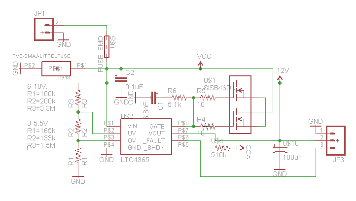
My favorite solution for the new board is the LTC4365 because it protects from under, over and reverse voltage. Does anyone use this chip?
I also found the TPS2400 which has under and over but no reverse protection.
Any other suggestions? Is it worth to spend 4$ (chip & mosfet) for the enhanced protection?

gregebert
Sep 10, 2019, 12:01:35 PM9/10/19
to neonixie-l
Interesting device, but I never used it.
Diode + fuse works good for reverse-protection, as long as the fuse and diode are properly sized (Start with the I-squared-t ratings)
My only concern with the example circuits is that there is no static discharge path for the gate-source connections on the MOSFETs. I would put a large resistor (10Meg; might be able to use even higher than that) across that connection to solve that vulnerability.
There is some transient-protection capability, and that's probably your biggest risk with a wall-wart supply failing. That info is at the end of the datasheet.

Kevin A.
Sep 10, 2019, 12:06:19 PM9/10/19
to neonixie-l
Why not just use a TVS diode for input protection?
--
You received this message because you are subscribed to the Google Groups "neonixie-l" group.
To unsubscribe from this group and stop receiving emails from it, send an email to neonixie-l+...@googlegroups.com.
To view this discussion on the web, visit https://groups.google.com/d/msgid/neonixie-l/ff67a859-2823-40d7-9230-bbb7ef19f70b%40googlegroups.com.
gregebert
Sep 10, 2019, 12:20:42 PM9/10/19
to neonixie-l
Many nixie designs I've seen here use boost-converters to generate the HV. When the supply voltage drops, the converter has to work much harder:
- Higher duty-cycle of the MOSFET
- Higher inductor peak-current, which is a risk for saturation
- And therefore, higher heat-producing RMS current in the MOSFET and inductor.
Those could lead to overheating and eventual burnout of the DCDC converter.
So, having under-voltage protection will provide better protection.
Kevin A.
Sep 10, 2019, 12:43:39 PM9/10/19
to neonixie-l
I see your point. For a clock that's running off of a decent quality wall wart, I dont see the added complexity of undervoltage compensation being necessary. If it were an automotive or battery powered application, sure.
--
You received this message because you are subscribed to the Google Groups "neonixie-l" group.
To unsubscribe from this group and stop receiving emails from it, send an email to neonixie-l+...@googlegroups.com.
To view this discussion on the web, visit https://groups.google.com/d/msgid/neonixie-l/0372f5c7-7a21-43e9-b29b-4cdbdeb57147%40googlegroups.com.
newxito
Sep 10, 2019, 3:41:21 PM9/10/19
to neonixie-l
I had to google TVS. Thanks for pointing out these diodes, they are indeed a good option.
But as perfectly described by Greg, undervoltage can be a real booster killer.
I think I will make a little board for the 2 devices and for the TVS diode option and make some tests.
gregebert
Sep 10, 2019, 3:51:18 PM9/10/19
to neonixie-l
My current clock went a bit overboard with self-checking; I have A/D converters on all supplies and software periodically monitors them for out-of-tolerance, and will shut-down the HV if that happens. There is also hardware-based detection of a gross power-supply failure that will instantly shut down the HVDC, just in case the RasPi crashed and cant monitor the supplies.
I was tempted to add a crowbar circuit that killed all of the supplies if an over-voltage condition occurred, but decided against that mainly because I did not want false triggers. The other reason is that if an overvoltage condition did occur, it's probably too late to save the clock because CMOS devices can get destroyed in nanoseconds if the zap is big enough. My main concern is the tubes; they are irreplaceable while the rest of the clock can be replaced. So, shutting-down the HV is sufficient.
There's plenty of ac-line protection, and I'm fairly certain that's where most of the trouble would originate from that could cause the power supply to run amok.

Robert L
Sep 11, 2019, 5:27:48 AM9/11/19
to neonixie-l
My modular clock controller pcb has a MAX4866LEUT and BSL308C MOSFET for input protection... ESD, over-, under- and reverse-voltage protection. Takes very little space using small SMD parts. My controller is a dense board and relatively costly... also a lot of effort to hand assemble. Thought the protection worth the effort and also wanted to try a circuit using the part.
Nice when 12V and 5V wall warts are sitting on the same bench and 12V gets plugged into the 5V controller. Have unintentionally tested this over-voltage protection at least once. :-)
Bob

ZY
Sep 12, 2019, 4:33:45 AM9/12/19
to neonixie-l
Do you have a suggestion on an A/D IC? Or are you using one from the uC directly? I'm looking to sprinkle some A/D everywhere for my nixie and non nixie projects just for fun.
On Tuesday, 10 September 2019 15:51:18 UTC-4, gregebert wrote:
My current clock went a bit overboard with self-checking; I have A/D converters on all supplies and software periodically monitors them for out-of-tolerance, and will shut-down the HV if that happens
Also on a similar but separate note, anyone have a suggestion on how to protect the filament (~1V) for VFD tubes? I'm always scared my buck converter will fail and pass Vin through the filament of my harder to fine VFDs.
Robert L
Sep 12, 2019, 9:39:25 AM9/12/19
to neonixie-l
Here are a few parts I use on a routine basis...
I2C digital pot - 10K shown, comes in other values: AD5259BRMZ10-R7 (DigiKey: AD5259BRMZ10-R7CT-ND $2.85/ea)
I2C 16-bit ADC: MCP3425A0T-E/CH (DigiKey: MCP3425A0T-E/CHCT-ND $2.24/ea)
I2C Isolator... float an ADC or other I2C parts at 200 VDC? ISO1540 (DigiKey: 296-34871-1-ND $4.80/ea)
Caution on the ISO1540... it is not symmetrical in that the "2" side can handle more capacitive load than the "1" side.
Did I mention I don't like manual set trim pots?
Is input protection worth $5 in parts? For me, it varies with the cost of the components at risk, complexity to rework or repair, probability of abuse... Most of my boards just have a PTC fuse, ESD and EMC mitigation. Some have current limiting high side switches. Only the controller has the full protection treatment. A fuse and ESD clamp are the bare minimum I'll use.
Robert L
Sep 12, 2019, 9:46:44 AM9/12/19
to neonixie-l
Forgot to mention on the ADC.
I also use the Arduino ADC for many projects - especially when I need multiple channels ground referenced. Include an LM4040 4.096V +-0.5% reference on one of the inputs and you can get quite good absolute accuracy if that's also needed. There are lower voltage reference parts if you're running a 3.3V system. (DigiKey LM4040CYM3-4.1-TR $0.33/ea)
Robert L
Sep 12, 2019, 9:49:20 AM9/12/19
to neonixie-l
Is input protection worth $5 in parts? For me, it varies with the cost of the components at risk, complexity to rework or repair, probability of abuse...
Forgot what may be the most important consideration... Am I repairing a board for my personal use, or is the board going to a user! It's worth a lot to me that a user never see a failure. Never. :-)
gregebert
Sep 12, 2019, 1:00:44 PM9/12/19
to neonixie-l
For filament protection on my NIMO project, I use individual 250mA fuses; the tube's filaments are rated for 200mA. The filaments require 1.1V, so I use a series dropping resistor and run them from a 2.5VAC transformer. This also reduces the inrush current-surge and that is the main reason why filaments fail. I also have a small FPGA that monitors the fuses, filaments and series resistors for burnout; software can query that at any time. The one flaw in my particular design is that it does not directly identify when parallel filaments burn-out. To do that I would need to monitor filament voltage and current, and my present design doesn't support that. Instead, I will have software monitor the total anode current of all tubes and by sequencing the tubes I can measure each one independently and infer when a filament is partially burned-out. This design was a bit more complex because I had to have a programmable DC offset for the filaments (I have a DAC for that).
An upcoming project with jumbo 7-segment VFD's and multiple parallel filaments will require a different approach, and I do intend to monitor and control the current & voltage for each individual tube. At least with this project, I dont need DC offset.
The ADC is use is a 16-channel MAX11632; it has a serial interface for programming and readback. If you've never used an ADC before, get ready to learn a lot and do some debugging; I've solved a lot of subtle issues. Now that I'm familiar with it and it's quirks, I'll likely stay with it.
I use a Raspberry Pi Zero-W for control because is has built-in WiFi and runs the whole Linux stack, for $10 US.
ZY
Sep 13, 2019, 5:18:45 AM9/13/19
to neonixie-l
Would you be able to elaborate on how the transformer prevents the inrush current? I'm a bit new to using transformers for anything. Also do you have a part number suggestion?
Currently for my ILC1-1/7 VFD project, I'm using a SiP2100 hbridge to generate my filament voltages that inverts itself at some frequency I selected. I've current limited the hbridge's Vin using a lm317, and fused the hbridge output. I was hoping the lm317 in current mode would prevent the inrush.
I was also wondering if adding a center tapped transformer to my hbridge output would help anything. I don't think with my setup I would have any brightness slant even without the transformer as the 5V and 0V are flipping as opposed to having one side of the filament constantly grounded. Also I'm wondering if I need to reduce my 5V value since the filament is rated for 5V, but I'm not sure if that's under a sign wave.
Anyway for the original question, I'm also interested in the LTC4365 IC after looking at the datasheet. I built a little circuit that I'll use to test it out:
gregebert
Sep 13, 2019, 2:31:26 PM9/13/19
to neonixie-l
The transformer doesn't play a significant role in limiting inrush current.
A filament behaves like a thermistor; at cold temperatures it has a lower resistance, but as it heats-up, it's resistance increases. So, when you connect a voltage source to it there is an initial surge current (I= Vsupply/Cold_resistance), and as the filament heats up the resistance increases. At some point, equilibrium is established and the radiated thermal energy prevents the filament from heating any further, hence the resistance stabilizes. After enough thermal cycling, the filament weakens. Not just hot/cold expansion & contraction, but also electromigration from what I've researched. Over time, the filament will develop narrowed regions and the wearout will accelerate to the point that local current-density is so high that it burns-out like a fuse. Long story short, how many times have you been surprised when the incandescent bulb dies when you turn it on ? Almost always, it's during turn-on.
As an example, I have a NIMO tube that varies from 2.7 ohms (cold) to 7 ohms (hot). If I follow the datasheet and connect a 1.1V supply to it, the surge current will be 400mA, which is twice the rated current. But if I drive it from 2.5V and add a series resistor of 5.5 ohms, the surge is reduced to 300mA. It may not sound like much, but considering these are extremely rare devices I'm not taking any chances. In the end, I chose an even higher series resistance because there was no visible difference in display brightness at lower filament current.
This approach is fine for single filaments; many devices, including NIMO tubes, have parallel-connected filaments. When 1 goes out, the tube is half-usable. But some large VFD tubes, like the ILC1-1/8 have multiple parallel filaments, and I think they could still work with 1 burned-out, so that means you will need a more-complex control circuit to limit the current as filaments burn-out.

Mac Doktor
Sep 13, 2019, 6:42:32 PM9/13/19
to neoni...@googlegroups.com
Excellent explanation, Greg.
On Sep 13, 2019, at 2:31 PM, gregebert <greg...@hotmail.com> wrote:The transformer doesn't play a significant role in limiting inrush current.A filament behaves like a thermistor; at cold temperatures it has a lower resistance, but as it heats-up, it's resistance increases. So, when you connect a voltage source to it there is an initial surge current (I= Vsupply/Cold_resistance), and as the filament heats up the resistance increases. At some point, equilibrium is established and the radiated thermal energy prevents the filament from heating any further, hence the resistance stabilizes.
A PTC thermistor. Just like the one in a color CRT that's in series with the degaussing coil. Ever notice how when you turned a cold computer monitor on there was a loud hum that faded out after a second or two? And if you turned it off and back on you heard nothing? That's because the thermistor was still warm.
After enough thermal cycling, the filament weakens. Not just hot/cold expansion & contraction, but also electromigration from what I've researched. Over time, the filament will develop narrowed regions and the wearout will accelerate to the point that local current-density is so high that it burns-out like a fuse. Long story short, how many times have you been surprised when the incandescent bulb dies when you turn it on ? Almost always, it's during turn-on.
I collect antique Xmas lights and preserving light bulbs 70~90+ years old is a big issue, especially with things like bubble lights that are not designed to be re-lamped. Miniature base lights were wired in series and typically rated 15V RMS. Mixing different types of bulbs is asking for trouble because the filaments have different characteristics. The one that heats up the quickest will be the first to blow. I use a Variac to slowly ramp the voltage up. Problem almost solved.
The final step is to use parallel-wired sockets and large 12V RMS transformers designed for low voltage outdoor lighting systems. Under load the output voltage is around 12.25V RMS.
As an example, I have a NIMO tube that varies from 2.7 ohms (cold) to 7 ohms (hot). If I follow the datasheet and connect a 1.1V supply to it, the surge current will be 400mA, which is twice the rated current. But if I drive it from 2.5V and add a series resistor of 5.5 ohms, the surge is reduced to 300mA. It may not sound like much, but considering these are extremely rare devices I'm not taking any chances. In the end, I chose an even higher series resistance because there was no visible difference in display brightness at lower filament current.
Exactly. I run my Xmas lights at ~15% below the rated voltage. When they were new the mains voltage in the US was 110V RMS, not 120V, so the voltage stamped on the bulb can't be trusted. A further complication is that the early NOMA bubble lights (which were made in huge quantities and still around) are stamped 14V and came in strings of 9 instead of 8. They can only be mixed with other types of bulbs safely by going to all this trouble.
This approach is fine for single filaments; many devices, including NIMO tubes, have parallel-connected filaments. When 1 goes out, the tube is half-usable. But some large VFD tubes, like the ILC1-1/8 have multiple parallel filaments, and I think they could still work with 1 burned-out, so that means you will need a more-complex control circuit to limit the current as filaments burn-out.
Just like putting LEDs in parallel with a common resistor which seems to be standard practice these disposable days. This is why amplifiers that use multiple transistors or tubes in parallel requires careful matching for maximum life.
Terry Bowman, KA4HJH
"The Mac Doctor"
Q: Should car stereo speakers be pointed to the rear for more thrust or up for more traction?
A. On long trips, the 20- to 30% improvement in gas mileage you might get with speakers pointing to the rear is certainly worthwhile. On the other hand, if you drive on snow or ice, the extra traction of speakers pointing upward gives you added control.
Don Lancaster
newxito
Sep 20, 2019, 4:59:21 PM9/20/19
to neonixie-l
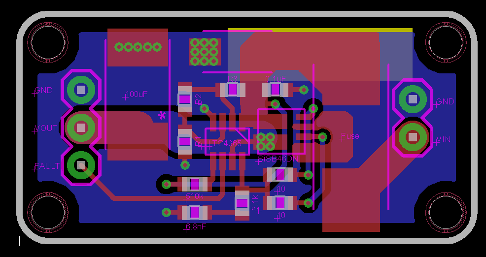
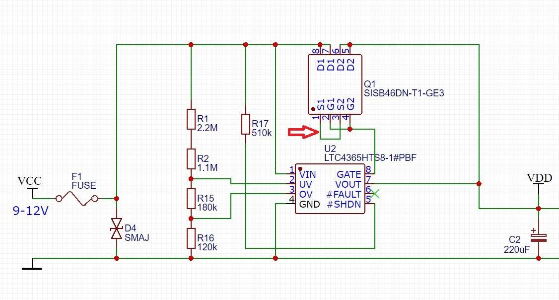
After some testing I decided to use the LTC4365 for the new clock board. I will implement the simple circuit without the gate resistors using the 2 channel mosfet (Q1) showed in the datasheet (SISB46DN). If I understand the circuit correctly, all the current (up to 2A \ 12V) will flow between the 2 source pins of the mosfet so I have a question about the trace. Does it make sense to add some vias on the source pins and add a bottom layer trace as well (blue) or is that a bad idea?
gregebert
Sep 20, 2019, 5:50:09 PM9/20/19
to neonixie-l
Is all of your load current going thru a via ? If so, use multiple vias unless there is a thru-hole component there soldered on both sides.
Plated-thru holes have a rather thin wall of copper which makes them less-conductive than traces.
newxito
Sep 20, 2019, 11:31:52 PM9/20/19
to neonixie-l
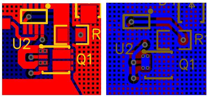
There are wide traces for VCC and VDD, that should be ok. My concern is about the trace between S1 and S2. Is it ok to have vias on a small landing pad? Is it ok to have 2 traces (1 direct and 1 thru vias) for the same connection?

gregebert
Sep 21, 2019, 1:36:54 AM9/21/19
to neonixie-l
Now I see how you've done your layout. No concerns about conductor sizing/shape.
Most of the time when I have SMT pads with a feedthru, they work fine. However on a current project I have a pair of SMT pads with a feedthru, and I have a very difficult time getting proper heating/solder-flow. The device is a large-ish NMOS transistor and the gate signal pin is not making good contact. I have similar structures in many other places on the board where the top and bottom side have SMT pads connected together by a via and they work fine.
But this one has different-size SMT pads connected by a via, and that has been a problem on both boards I've built, and at no other location. I suggest you make sure the 4 feedthru holes are larger than minimum-geometry (they look like they probably are) and you may want to pre-fill the feedthrus with solder before mounting Q1. You should then be able to heat from the backside and see good solder-flow on the top-side without actually heating from the top side. That should guarantee a good connection.
Reply all
Reply to author
Forward
0 new messages