How much voltage do cathode transistors need to be able to handle?

alex nolan

Bill van Dijk
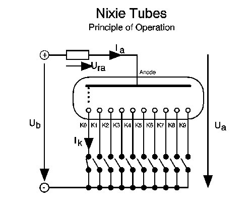
According to Mr. Ohm, the voltage drop over a resistor is equal to the resistance multiplied by the current. In the off state, the current is 0A, so regardless of the value of the anode resistor, the drop over the anode resistor is 0V. The switching transistor therefore sees the full voltage minus the internal drop in the tube.
Bill
--
You received this message because you are subscribed to the Google Groups "neonixie-l" group.
To unsubscribe from this group and stop receiving emails from it, send an email to neonixie-l+...@googlegroups.com.
To post to this group, send email to neoni...@googlegroups.com.
To view this discussion on the web, visit https://groups.google.com/d/msgid/neonixie-l/d1f607aa-b969-4288-be51-c6bbf4f23fdf%40googlegroups.com.
For more options, visit https://groups.google.com/d/optout.

|
This email has been checked for viruses by Avast antivirus software.
|
Bill van Dijk
On re-reading your message, if one digit is lit, the voltage drop over the anode resistor can be calculated according to Ohm's law, and determines the "real" voltage present at the tube's anode (Ub - Ura). The remaining open switching transistors now see the calculated anode voltage minus the internal tube voltage drop. This is usually in the order of 70V or so, depending on your tubes and supply voltage. That voltage would jump significantly if all digits were switched off simultaneously, the condition I described in my first reply since there would now be 0V drop over the anode resistor. For that reason tube blanking should not be done by opening all cathode transistors unless they can handle that voltage.
Bill
To view this discussion on the web, visit https://groups.google.com/d/msgid/neonixie-l/006001d10d8c%2451ed1710%24f5c74530%24%40com.
For more options, visit https://groups.google.com/d/optout.
alex nolan

taylorjpt
If you look at Fig20 of the above data sheet, it shows the voltage on the "6" cathode transistor while the tube cycles continuously from "0" to "9". As you can see, the voltage on the transistor is not a single voltage but depends on its relationship to the other cathodes in the tube.

gregebert

David Forbes
The Nixie tube is not at all a resistive device. It's like a 150V Zener
diode. Therefore, your analysis doesn't make sense.
The Nixie tube has the ability to stand off about 70-100V before current
flows, and then the current is microamperes. You can do this test easily
with a potentiometer to supply a variable voltage (0-150V) to the tube,
and a ~10K series resistor tying all cathodes together to the negative
supply voltage. Measure the voltage across the 10K resistor as you turn
up the voltage. Ohm's Law will tell you how much current is flowing for
a given tube voltage.
On 10/23/15 11:00 AM, gregebert wrote:
> If you consider the nixie to be a resistive device,
> it's voltage-drop will be about zero. Therefore, almost the entire anode
> voltage will appear across the driver.
>
David Forbes, Tucson AZ
Bill van Dijk
As you can see, no shortage of confusing answers and opinions. I thought science long ago abandoned the opinion or Socrates approach: -if one reasons long enough, the truth will reveal itself- long ago in favor of the empirical options. David Forbes is correct that the nixie behaves more like a zener, and cold cathode tubes (what a nixie essentially is) were often used as voltage stabilizers in the old tube era for exactly that property.
I am somewhat at a loss to what you are trying to accomplish. The voltage value you are looking for varies, and at best you may establish a range for your tubes. It may vary from 70 up to as much as 100V. If you are looking for a transistor to use, I'd recommend the MPSA42 for low side switch, and an MPSA92 for the high side if you wish to implement tube blanking. They are cheap, plentiful, and available in through hole as well as SMD. They have never failed me on any nixie tube so far. Check E-Pay for pricing if you are not in a rush.
Hope that helps
Bill
To view this discussion on the web, visit https://groups.google.com/d/msgid/neonixie-l/8f746afa-cf38-46e6-b7af-53de985d2250%40googlegroups.com.
For more options, visit https://groups.google.com/d/optout.

marta_kson
If not You can clamp the voltage to a lower level and use lower rated transistors. The clamp must be there, transistors degrade from breakdown even if they don't may fail immediately when the current is limited. The needed clamp voltage minimum level can sometimes be found in the tubes datasheet. Look for "selection voltage".
The antique 74141/7441/K155ID1 are such devices. The western parts have a 60-something clamping voltage, the soviet versions about 100V. Those are good for any tubes. Unfortunately they are power hungry at about 25mA, otherwise they are a good choise. The K155ID1 use to be readily available at eBay.
Some tubes have very low selection voltages. I have some recollection of ZM1000 to be such a device.
I also remember having seen some clock built with 40?? CMOS at 15V driving nixies directly. The protection diodes to Vdd was used for clamping. That's a bad pracice that could possibly damage the devices even if Vdd is safely held down by some means to ensure it won't rise.
gregebert
I also remember having seen some clock built with 40?? CMOS at 15V driving nixies directly. The protection diodes to Vdd was used for clamping. That's a bad pracice that could possibly damage the devices even if Vdd is safely held down by some means to ensure it won't rise.
