Single inductor supplies and heat issues
170 views
Skip to first unread message

Oyvind
Nov 6, 2018, 3:12:29 AM11/6/18
to neonixie-l
Hi,
I have been experimenting a bit with single inductor supplies. I built one myself based on TPS40210, and tried a couple of others too.
Common for all, is that the inductor gets quite hot when running them on a 10K dummy load @180V.
So, for 6 IN-14 tubes on 1.5 mA each, they work just fine, but not much more than that.
I tried various inductors, with fairly high amp ratings:
- shielded SMD ones have most pronounced. That is, I can hold my finger on it, but just barely.
- radial THT, souch as Bourns RLB9012-101KL. When peeling off the outer coating, the heat is obvious
- toroids with low ohms / high amps. These gives best result, but gets "luke warm".
I'm thinking that having a supply like that inside a casing would not be good in the long run. I am aiming for non-multiplexed..
Not sure how to remedy this (snubber or similar ?), perhaps this topology isn't the most ideal.
What's your experiences here ?

gregebert
Nov 6, 2018, 8:28:06 AM11/6/18
to neonixie-l
Most likely., the inductor is exceeding it saturation current. That is the point where additional current does not add much magnetic energy, and at that point you will see an increase in lost energy (heat).
Try an inductor witrh the same inductance, and a higher Isat rating.
My experience with any sort of switching converter is that they work great at low loads, and as you increase the load you see more problems.
gregebert
Nov 6, 2018, 12:02:48 PM11/6/18
to neonixie-l
Also, be sure to use a scope and look carefully through the design. The switching device (most likely a MOSFET) is susceptible to voltage overstress, so make sure the drain-source voltage is not exceeded, and especially not the gate-source voltage because it is a very thin oxide that can only withstand low voltages, on the order of 10-20 volts.
If you can place a small resistor, say 0.1 to 1.0 ohms, between the source lead and GND, you can use a scope to monitor peak transistor current, which in-turn will be the peak inductor current. It must remain below Isat.
The transistor is subject to heating as well, depending upon its Rds (on) spec and the RMS current thru the inductor. Switching losses are probably small, but the only way to know is to measure the drain-source voltage simultaneously with the drain current. Some fancy scopes might calculate this for you, otherwise you can export data-samples to excel and calculate the switching energy per-cycle.
Knowing the RMS current thru the inductor, and it's resistance, you can calculate the resistive power dissipation; this does NOT include any magnetic losses due to hysteresis or saturation.
If you are running at high frequencies, such as hundreds of kilohertz, other things will creep-in and bite you.
Oyvind
Nov 7, 2018, 4:24:54 AM11/7/18
to neonixie-l
The FET's (and diodes) I'm using, are well within the specs. None of those show any sign of heat at all. Also, I am using FET's with low QG/Rds etc.
My own supply uses a current-sense resistor, which I can be used for measuring purposes.
Most of the commonly used supplies runs around 40-60kHz, and uses 100uH inductors (DCM).
I am actually looking into using (much) higher inductance and higher frequencies. So far simulations looks OK, and I get "CCM-ish" curves and reasonably good efficiency. Will do some more simulations before I make a test board.
What particular things are you thinking about ?

Jon
Nov 7, 2018, 7:07:13 AM11/7/18
to neonixie-l
On Tuesday, November 6, 2018 at 1:28:06 PM UTC, gregebert wrote:
Try an inductor witrh the same inductance, and a higher Isat rating.
I had the same problem that Oyvind is describing and uprating the inductor fixed it nicely. I haven't had the time to go back and quantitatively analyse the circuit behaviour to understand exactly how I got it wrong in the first place - the original inductor choice should have been OK. But perhaps in practice you have to allow much more margin on Isat than I had assumed.
Jon.
gregebert
Nov 7, 2018, 1:02:31 PM11/7/18
to neonixie-l
Be careful about simply increasing the inductance, because that can actually reduce the amount of energy-per-cycle, hence the power, assuming constant frequency.
Energy = 1/2 LI^2, and from V = Ldi/dt , you can infer energy-per-cycle = 1/2 (V^2) * (T^2)/L
In other words, to increase the energy-per-cycle, you want to increase the voltage or the duty-cycle.
If your duty cycle is getting too high, change the inductor to a transformer (flyback converter). A transformer is just 2 coupled-inductors, and it's fairly easy to model that in SPICE.
Be careful about the coupling factor, because it's not 1.0, and as it's reduced you will see increasing spikes across your MOSFET when it switches off.

Grahame
Nov 7, 2018, 1:05:57 PM11/7/18
to neoni...@googlegroups.com
Oyvind
Nov 7, 2018, 3:25:30 PM11/7/18
to neonixie-l
Yep, and there is the problem with the voltage ratio (from 12V in my case).
Coupled inductors are also made by several manufacturers. These are often customized for specific applications, but there are some off-the-shelf ones. I guess I would need something like 1:10 windings.
I find it somewhat difficult to design it though, as most literature describes step-down. I guess there is more to it than just slamming a transformer into a boost topology.
- Oyvind
Oyvind
Nov 7, 2018, 3:26:02 PM11/7/18
to neonixie-l
Thanks, interesting page indeed !
- Oyvind

threeneurons
Nov 12, 2018, 3:45:51 PM11/12/18
to neonixie-l
I think your doing something wrong. I use the RLB9012-101KL routinely, and get twice the output current (~35mA @ 180V), while the coil gets warm, but still within reason. I'd suggest that you increase your switching frequency. I suspect you're well into saturation.
Oyvind
Nov 14, 2018, 3:24:36 AM11/14/18
to neonixie-l
Hi,
first: interesting & very useful webpage ! (recognized your nickname). Appreciate people who share information like that.
Increasing frequency will only result in maxing out duty cycles. Not sure if I tested the RLB on >= 60kHz yet though, I'll
give it a go later.
What frequency are you at, approximately ?
Assuming you're using the MC34063, I'm not sure how the PWM scheme looks on that one. Have you tried peeling off
the outer shrink tube on the inductor ? At first I didn't think there was any significant heat, until I realized the shrink tube
was messing with me.
Anyways, I found some nice off-the shelf transformers which looks very promising in simulation, so I'm heading for
flyback. Slightly more expensive though, but not a concern for me.
- Oyvind
Jon
Nov 14, 2018, 5:53:47 AM11/14/18
to neonixie-l
On Wednesday, November 14, 2018 at 8:24:36 AM UTC, Oyvind wrote:
Anyways, I found some nice off-the shelf transformers which looks very promising in simulation, so I'm heading forflyback. Slightly more expensive though, but not a concern for me.
Can you share some more specifics and/or a link?
Jon.
Oyvind
Nov 14, 2018, 6:16:30 AM11/14/18
to neonixie-l
Can you share some more specifics and/or a link?
Sure ! Actually, I was about to order customized transformers from China (can be done for ~$45 for 5 pcs), when I discovered this page in the last moment:
The specific ones are listed here:
These are 1:10, with 10uH on the primary.
The specs on DA2032 looks fine for my simulations so far, optionally DA2033 for heavier lifting.
I'm gonna try to increase the frequency and see how the transformer responds to that, in order to reduce peak to peak.
Hopefully I get to design the PCB and order parts during this weekend...

petehand
Nov 15, 2018, 3:39:42 AM11/15/18
to neonixie-l
In my opinion, 100uH is a bit low for a frequency of 40-60kHz. I would use at least 220uH. For estimating saturation current, multiply the total load current by the voltage step-up and double it (since the input current is a triangle). So if you want 15mA at 180V from a 12V supply, you can expect a peak primary current of (180/12)*0.015*2 - you should be looking for an inductor with a saturation current of at least 0.5A.
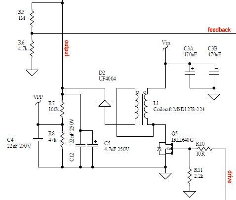
You can ease the strain on your driver transistor by using a split coil inductor - the transistor only sees half the secondary voltage. This is the generator I use on my FLW design that can drive 50mA at 180V.

jörg
Nov 15, 2018, 6:18:23 AM11/15/18
to neonixie-l
I build a PWS using the DA2032. I'm very satisfied with it. The FET's and Transformer warm up about max 30 degrees C.
If you like, take a look at my video, it shows the PWS driving a GIPS-16-1 tube.
Cheers,
Jörg
If you like, take a look at my video, it shows the PWS driving a GIPS-16-1 tube.
Cheers,
Jörg
Oyvind
Nov 15, 2018, 9:05:57 AM11/15/18
to neonixie-l
Nice !
Searched for "GIPS-16-1" on youtube, and found this one with that transformer.. so that must be you, right ? :D
How much power is it pulling ?
threeneurons
Nov 15, 2018, 5:57:28 PM11/15/18
to neonixie-l
Yes, I like using the old MC34063. Its a relatively simple chip. But don't get stuck on the semiconductors. The coil is the main player. And real inductors behave a lot differently than ideal inductors. More so than capacitors and resistors, when comparing the ideal model with the real parts. For power applications, the inductance changes (to a lower value) as current increases. This happens well before the part goes into saturation, so any calculations made, are just a first stab. In reality, you may have to go 2 to 4 times higher, than calculated.
In practical matters I like using coils with E3 values (E3 meaning significant figures of 10, 22 & 47). With the MC34063, I can change base frequency with the timing cap. Smaller caps can be found, cheaply, in a wider range of values (E6 - 10, 15, 22, 33, 47, & 68). E12 or higher only with resistors (E12 - 10,12,15,18,22,27,33,39,47,56,68,82).
You can get more power out of an SDR1806, but before going there you aren't get all the power out of the RLB9012. If you can't easily change frequency, then increase the inductor size. Buy some 220uH coils, though you should be able to get more power out of the 100uH part. I routinely get more than 30mA out, at nixie voltages.
On Wednesday, November 14, 2018 at 12:24:36 AM UTC-8, Oyvind wrote:
Hi,

orange_glow_fan
Nov 15, 2018, 6:40:34 PM11/15/18
to neonixie-l
Wow, that video is amazing! Any idea as to what these new Nixies sell for? An arm?, leg? first born??
Oyvind Idland
Nov 16, 2018, 2:15:43 AM11/16/18
to neoni...@googlegroups.com
Forgot to mention that I have tried inductors from 100 - 270 uH range in various frequency combinations. I also simulate stuff,
preferably using LTSpice (using TINA on most TI chips due to lack of spice-models).
The inductors were selected to be well above the peak-peak from simulations.
Most chips can have the frequency configured easily by replacing a resistor and/or capacitor. My experiments have been in the 40-60 kHz range.
--
You received this message because you are subscribed to the Google Groups "neonixie-l" group.
To unsubscribe from this group and stop receiving emails from it, send an email to neonixie-l+...@googlegroups.com.
To post to this group, send email to neoni...@googlegroups.com.
To view this discussion on the web, visit https://groups.google.com/d/msgid/neonixie-l/df6e07fc-cc45-4196-86d4-8c5fef998aaf%40googlegroups.com.
For more options, visit https://groups.google.com/d/optout.
jörg
Nov 16, 2018, 7:48:34 AM11/16/18
to neonixie-l
Yes,
this is my prototype.
I like the open possibilties to drive the tube directly. I get the warm display glow and plenty more options like showing text or graphics.
I will stresstest the PWS and post the results.
Thanks for viewing the video. I will try to make a better quality one.
Cheers,
Jörg
this is my prototype.
I like the open possibilties to drive the tube directly. I get the warm display glow and plenty more options like showing text or graphics.
I will stresstest the PWS and post the results.
Thanks for viewing the video. I will try to make a better quality one.
Cheers,
Jörg

GastonP
Nov 16, 2018, 8:24:55 AM11/16/18
to neonixie-l
The usual auction site is your friend... ;)
40-50 USD each, depending on the state of disassembly of the original part, with free shipping.
Reply all
Reply to author
Forward
0 new messages