How to mount IN-9 tubes

John Murphy
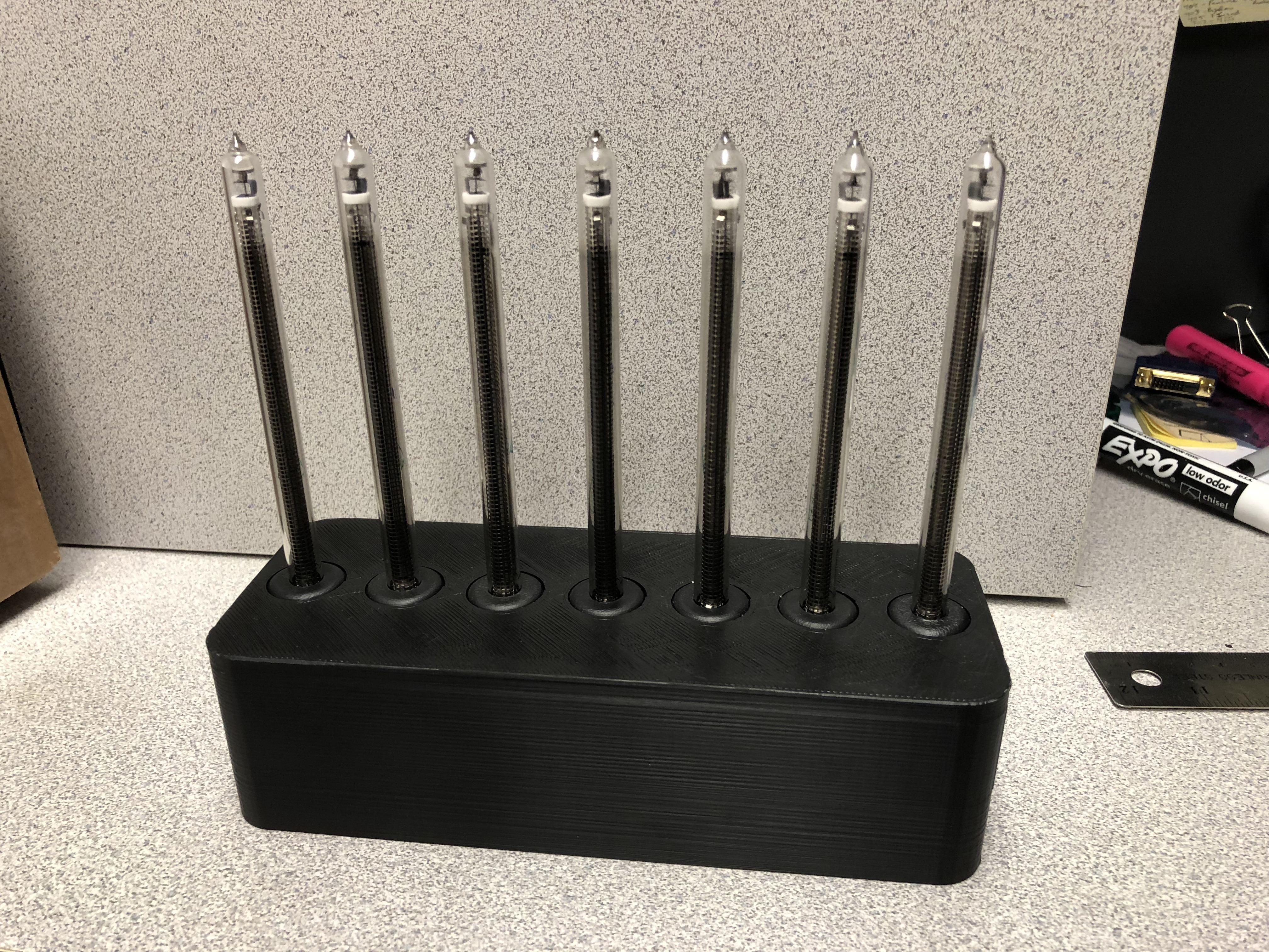
I'm building an audio spectrum analyzer using the MSGQ7 chip, an Arduino, and 14 IN-9 tubes (7 Left channel and 7 Right). I've got everything working on the bench, but now it's time to get things mounted for display! I'd like to have the tubes stand vertically next to each other. I'm looking for suggestions on how to securely mount these tubes. If possible, I would prefer to mount at the bottom only so that the top of the tubes are free and clear.

Joe Croft
I'm building an audio spectrum analyzer using the MSGQ7 chip, an Arduino, and 14 IN-9 tubes (7 Left channel and 7 Right). I've got everything working on the bench, but now it's time to get things mounted for display! I'd like to have the tubes stand vertically next to each other. I'm looking for suggestions on how to securely mount these tubes. If possible, I would prefer to mount at the bottom only so that the top of the tubes are free and clear.
--
You received this message because you are subscribed to the Google Groups "neonixie-l" group.
To unsubscribe from this group and stop receiving emails from it, send an email to neonixie-l+unsubscribe@googlegroups.com.
To post to this group, send email to neoni...@googlegroups.com.
To view this discussion on the web, visit https://groups.google.com/d/msgid/neonixie-l/338d353d-1069-4d2a-8809-b8d64dc23e98%40googlegroups.com.
For more options, visit https://groups.google.com/d/optout.

SWISSNIXIE - Jonathan F.
See https://www.nocrotec.com/shop/images/content/colon-02.jpg
Another possible solution would be to use a slotted-pc board and then glue in the whole tube base with kind of silicon glue (sticky but flexible).
Another version would be this:
https://threeneurons.files.wordpress.com/2015/02/ntherm01s.jpg

John Rehwinkel
- John

alb.001 alb.001
Use a black backer board ( you can spray paint some pc board with black spray paint ) then use black thread - I use black silk suture thread to support them. Almost invisible and very strong but with some give if needed.
Phil
--
You received this message because you are subscribed to the Google Groups "neonixie-l" group.
To unsubscribe from this group and stop receiving emails from it, send an email to neonixie-l+...@googlegroups.com.
To post to this group, send email to neoni...@googlegroups.com.
To view this discussion on the web, visit https://groups.google.com/d/msgid/neonixie-l/615f643c-69ad-4331-9c5d-3508b3998a16%40googlegroups.com.

Terry Kennedy
I'm building an audio spectrum analyzer using the MSGQ7 chip, an Arduino, and 14 IN-9 tubes (7 Left channel and 7 Right). I've got everything working on the bench, but now it's time to get things mounted for display! I'd like to have the tubes stand vertically next to each other. I'm looking for suggestions on how to securely mount these tubes. If possible, I would prefer to mount at the bottom only so that the top of the tubes are free and clear.


John Murphy
On Monday, February 19, 2018 at 7:07:17 AM UTC-5, John Murphy wrote:
John Murphy
On Monday, February 19, 2018 at 7:07:17 AM UTC-5, John Murphy wrote: