Raspberry PI controlled Nixie display

okniew
Hello everyone!
I’m new to this group and this is my first post.
I’m looking forward to design & build a particular project with Nixie display, but since I’m really not an expert and just starting, I would very much appreciate your help & feedback. I do have some specific questions (in the end), but if you look at project goal & design principles and think of better way to do things – please comment as well!
Project goals:
A Raspberry PI controlled Nixie display, with some additional LED indicators for weather conditions. Nixie display will be used to display the time or temperature or humidity, depending on settings.
Main assumptions:
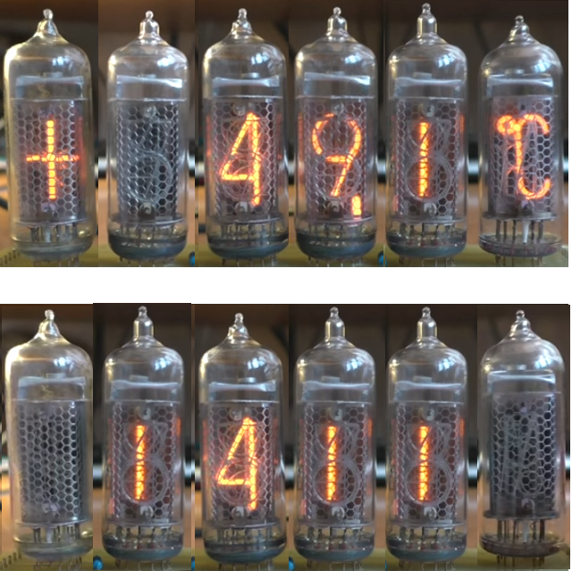
1. 6 lamps: IN-19V ("+"/"-"), 4 x IN-14 ("0" - "9" + 2 dots), IN-19A ("C"/"%")
2. Ability to control Nixie brightness (by Raspberry PI)
3. LED RGB back-light under each tube, with color & brightness controlled (by Raspberry PI)
The look I want to achieve:
Design principles:
1. As much as possible – use the components available on the market. I’d like to avoid designing PCBs, avoid designing custom circuits, minimize soldering, etc. I understand I’ll have to do those things to some extent, but being a newbie, I want to minimize room for failure or issues.
2. A single visible power supply for the whole thing, from 230V AC outlet, driving all 6 nixies (180V, 30mA), Raspberry (5V, 3A) and the LEDs.
3. All components should be ideally driven by Raspberry I2C bus interface, using which I could control separately: displayed value of each tube, brightness of each tube, color & brightness of each LED. I think this is the easiest and most versatile approach (but again – looking for confirmation / other suggestions)
Questions to start with:
1. Are there any available to be purchased components, which you could recommend, fulfilling above design principles & goals? Right now, I have the Raspberry & the tubes, but nothing “in between” J
2. Do you think my idea of controlling all components via I2C bus is a good idea? I want to go for the easiest and most versatile approach.
3. Are there anywhere existing sockets for IN-14 / IN-19 tubes? Or will I have to solder to tubes to whatever components I select?
Thanks a lot for your help!

Nick

Alic
Does it have to be RPi? There are many options available for arduino, but for some reason not many for the RPi (that I know of).
I think all options already include the 5V/3.3V and HV power-supply.
Here someone uses an RPi 0 with the Arduinix shield/HAT :
https://hackaday.io/project/16467-raspberry-pi-zero-nixie-clock
Concerning the power supply:
I have never seen a nixie-object where more than one voltage supply was outside.
Especially the HV supply is always close to the board.
I am still searching for a universal nixie (direct) drive board which has just connections for the cathodes, 5V or 12V supply, HV supply control (output enable?) and one of the serial interfaces compatible with arduino and RPi.
Swissnixies Sunix - S comes very close :
http://www.swissnixie.com/index.php?go=sunixs

Tomasz Kowalczyk
Nick
Alic
Tayloredge offers a HV power supply which gives up to 23mA @ 180V for a 5V input :
http://www.tayloredge.com
Alic
http://www.ebay.com/itm/131846790948?_trksid=p2060353.m1438.l2649&ssPageName=STRK%3AMEBIDX%3AIT
http://www.ebay.com/sch/vfdclock/m.html?_nkw=&_armrs=1&_ipg=&_from=

Ian Vine
You received this message because you are subscribed to the Google Groups "neonixie-l" group.
To unsubscribe from this group and stop receiving emails from it, send an email to neonixie-l+unsub...@googlegroups.com.
To post to this group, send an email to neoni...@googlegroups.com.
To view this discussion on the web, visit https://groups.google.com/d/msgid/neonixie-l/a0e53346-0539-433f-a048-30993f66c80f%40googlegroups.com.
Tomasz Kowalczyk

gregebert
Ian Vine
To post to this group, send email to neoni...@googlegroups.com.
To view this discussion on the web, visit https://groups.google.com/d/msgid/neonixie-l/bbaec5c1-f189-4fa0-8bf8-c8e947c5fa87%40googlegroups.com.
okniew
okniew
W dniu poniedziałek, 20 marca 2017 10:42:24 UTC+1 użytkownik okniew napisał:

Dylan Distasio
--
You received this message because you are subscribed to the Google Groups "neonixie-l" group.
To unsubscribe from this group and stop receiving emails from it, send an email to neonixie-l+unsubscribe@googlegroups.com.
To view this discussion on the web, visit https://groups.google.com/d/msgid/neonixie-l/c135c889-7a03-41a4-87d7-78c96b2f245e%40googlegroups.com.

Dave
If anyone wants to try one, I have some extra PCBs I can sell.
gregebert
WiFi range seems adequate, especially considering the antenna is integrated into the PC board.
I run VNCserver on the Pi, and connect from one of my systems (no monitor or keyboard on the Pi)
Power consumption w/ AC adapter is quite low, perhaps 1watt based on my low-resolution AC-line monitor.
GPIO speed, using wiringPi and a compiled C program gave a max frequency of 5Mhz on a single pin.
I'm going to explore speeds using serial and parallel modes in the coming days.
At first glance, it seems to be adequate for use with serial driver chips like the HVxxxx series family.
It took very little effort to install wiringPi and get the GPIO working; worked on my first attempt!
I'm satisfied to the point I wont pursue Arduino anymore.
Having a $10 Linux-based platform that I can log into wirelessly & remotely is really incredible.

Mitch
Starting with an environment reasonably similar to Arduino would make an easier and more comfortable learning curve.
gregebert

GastonP
<snip>
On Saturday, April 8, 2017 at 4:02:13 AM UTC-3, gregebert wrote:
UPDATE: I have my RasPi Zero W running nicely as a headless system w/ Raspian.
I'm satisfied to the point I wont pursue Arduino anymore.
Having a $10 Linux-based platform that I can log into wirelessly & remotely is really incredible.
Just be aware that Linux is not a real time operating system, so anything that is time-sensitive has high risk of those timings eventually not being respected.
I use one of the multiple Pi lookalikes just out of cost considerations (OrangePi).
For tasks that do not require much processing grunt I go for the Texas Instruments family of mixed signal processors, and having AVR being recently acquired by Microchip gives me the sense that Arduino's final day is coming soon.
gregebert
gregebert
Typically, I'm getting around 32usec (measured on a scope) to send the 64-bit burst, which is decent for software-controlled GPIO's.
There are timers available in wiringPi, but I found they are not accurate. A burst that measures ~32usec on my scope is around 22usec per the micros() call.
Despite it's inaccuracy, it's still useful for generating histogram data on transmit times. As GastonP pointed out, timing is non-deterministic in Linux. After numerous runs I did see a case where it took 10msec to complete the transmit. The single outlier really skewed the avg TX time.
Bottom line is that the RasPi is usable for many, but not all, control applications. A clock should be OK; engine controller ? No way.
All of my clocks to-date are at least as reliable as the electric utility (never had logic or FPGA crash on me); not sure if RasPi has similar reliability / availability.
400 Loops. Max_time = 10083usec, Min_time = 18usec, Avg_time = 45.69usec
0 to 20: N = 161
20 to 25: N = 219
25 to 30: N = 18
30 to 35: N = 0
35 to 40: N = 1
40 to 45: N = 0
45 to 50: N = 0
50 to 60: N = 0
60 to 70: N = 0
70 to 100: N = 0
100 to 150: N = 0
150 to 200: N = 0
200 to 300: N = 0
300 to 400: N = 0
400 to 500: N = 0
500 to 750: N = 0
750 to 1000: N = 0
1000 to 2000: N = 0
Over 2000: N = 1
Nick

blave

Charles MacDonald
> You could always use a genuine real-time o/s like ChibiOS/RT ..
https://www.linux.com/blog/intro-real-time-linux-embedded-developers
https://wiki.archlinux.org/index.php/Realtime_kernel
would that be close enough?
--
Charles MacDonald Stittsville Ontario
cm...@zeusprune.ca Just Beyond the Fringe
No Microsoft Products were used in sending this e-mail.
gregebert

blkadder
I will be watching this thread as well as the Arduino thread. Thanks to all for posting excellent information.
Ron
...Semper Fidelis...
gregebert

Terry Kennedy
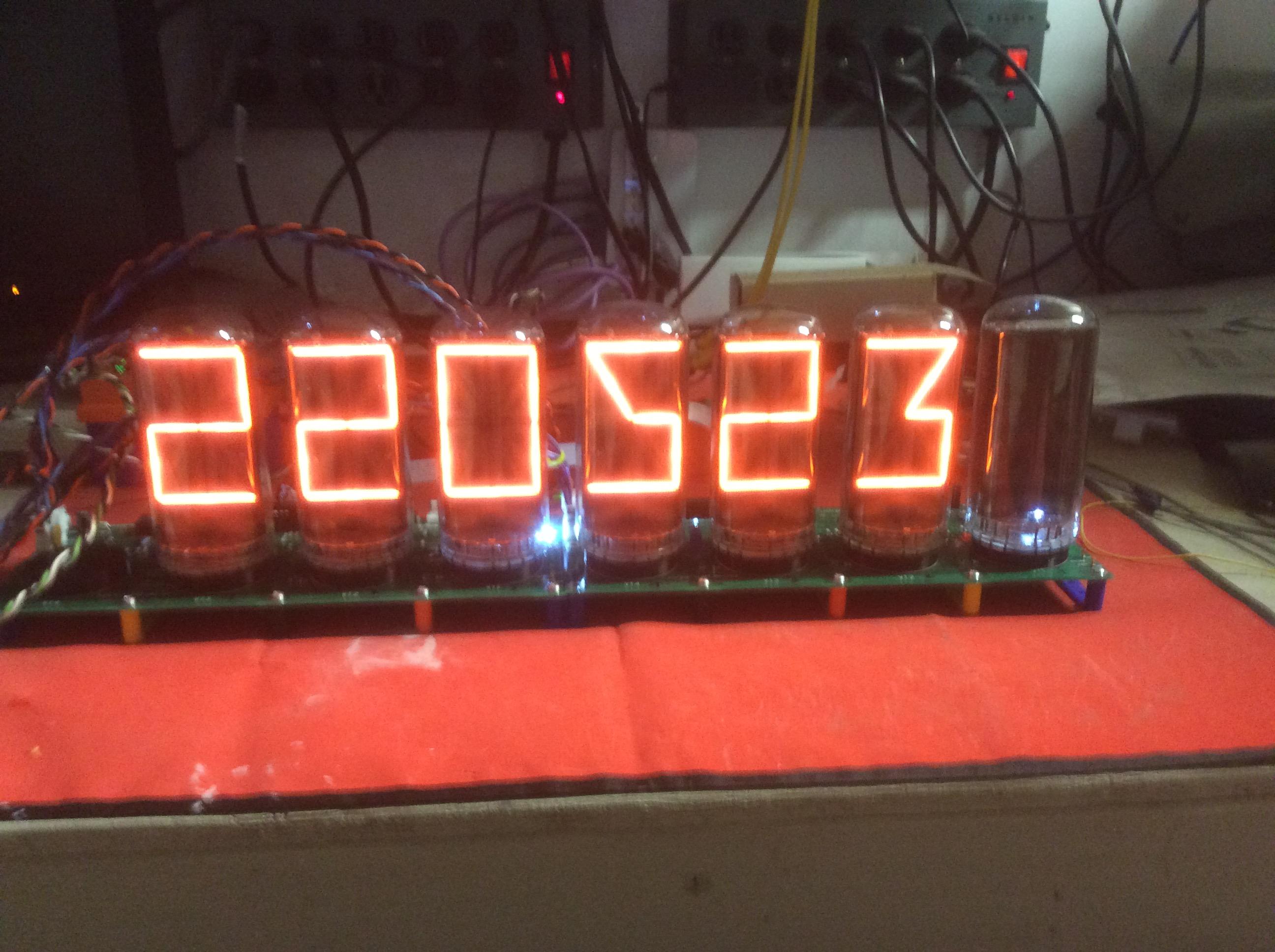
Photo here, and short video posted to YouTube at https://youtu.be/OjQeW67viXw
gregebert
gregebert
- No 'helper' FPGA is needed; there is far more than enough horsepower in the Pi to handle all of the compute, timekeeping, and serial communications
- Timekeeping is accurate; the Pi periodically syncs to a time-source on the internet (no idea where). Perhaps it's from my router, which gets the time elsewhere.
- Display updates are done once per second. I have never observed my display 'jump' or 'stall' +/- 1 second based on the random alignment between realtime, and when the clock software updates the display. I did not add any code to attempt to synchronize to realtime.
- CPU utilization is averaging 3-4%, even when running a VNC server, plus all of the Linux housekeeping tasks. There are periodic spikes of ~40% each second when the clock software does it's work. No significant thermal generation (less than 10 degrees F as measure with infrared thermometer)
- Using a cheap passive IR (PIR) sensor has allowed me to shut-down the tubes most of the time; the sensor is sensitive enough that I really cant sneak-up on my clock without it turning on. Nor is it falsely triggering.
- GPIO programming with WiringPi is fairly easy; there were some quirks that I found and fixed when reading a digital input. Also some minor documentation issues about pin-naming.
- Being able to remotely program without attaching/removing cables, power-cycle, etc is very handy. I use 'C' because it's compiled, hence faster execution versus python, perl, etc.
- Only drawback so far is the startup-time (linux boot), which is just under a minute. I have not yet added the clock software into the bootup process so that it auto-starts on power-up; should be easy to do in crontab ? (I've done it before for a remote server; just cant remember where).
- Without an attached RTC module, timekeeping relies on my internet service and WiFi running. I have thought about adding an RTC module as a backup, but it's low priority.

Paul Andrews
- Paul
Mitch
gregebert

neoni...@liny.net
To add a little bit more to what he mentioned, you may want to have a script that accepts a parameter indicating if it's "start", "stop" or "restart" (e.g. stop then start) for the daemon. Then within the /etc/init.d/ dir you put your script. It must have a standard LSB header and you run a command (see 2nd link) so the system knows how to connect all the parts. This way for shutdown (or restart) your clock code can accept a shutdown request (in your clock program C code catch a SIGTERM or other 'signal') and gracefully put any GPIO pins to a safe state before exiting. Restart is handy after you've swapped in a new program version. For that once in a blue moon instance when your program won't shut down gracefully, you can in your script also code a "kill" section that sends a SIGKILL to your program.
In the script you also choose at what run-level you want the clock program to run. Typically, that would be 2, 3 & 5. See http://www.tldp.org/LDP/sag/html/run-levels-intro.html for run-level info, which also talks a little about the /etc/init.d/
A decent RPi example & explanation of what's needed with some shell start/stop code is here: http://raspberrywebserver.com/serveradmin/run-a-script-on-start-up.html I haven't verified it works, but the shell scripting looks OK from my Red Hat perspective.
Good luck and have fun!
- Steve
You received this message because you are subscribed to the Google Groups "neonixie-l" group.
To post to this group, send an email to neoni...@googlegroups.com.
To view this discussion on the web, visit https://groups.google.com/d/msgid/neonixie-l/6ef0cef0-e433-4ecf-839a-fbd8f98838dd%40googlegroups.com.
gregebert
The real question now is: How long can a raspi run without crashing ?
Eventually I will start logging usage of each segment, on each tube, and use that for depoisoning. Since it's a micro SD (flash) filesystem, which has limited write-cycles, I have to be careful about how often I store runtime information. Syncing daily to the same file (appending) could cause wearout after several years if the OS doesn't incorporate some form of levelling. Doing it every 3-4 days should get me about 100 years of logging if the flash has 10K write-cycle endurance. Not that I will be around then to do anything with that data.....

Paolo Cravero
The real question now is: How long can a raspi run without crashing ?
Eventually I will start logging usage of each segment, on each tube, and use that for depoisoning. Since it's a micro SD (flash) filesystem, which has limited write-cycles, I have to be careful about how often I store runtime information. Syncing daily to the same file (appending) could cause wearout after several years if the OS doesn't incorporate some form of levelling. Doing it every 3-4 days should get me about 100 years of logging if the flash has 10K write-cycle endurance. Not that I will be around then to do anything with that
OTOH Linux systems log stuff all the time to disk, so that part of the flash disk might fail before your clock log sectors.