Would anyone mind looking over my schematic?
122 views
Skip to first unread message

Thomas Kummer
Sep 3, 2018, 7:21:08 PM9/3/18
to neonixie-l
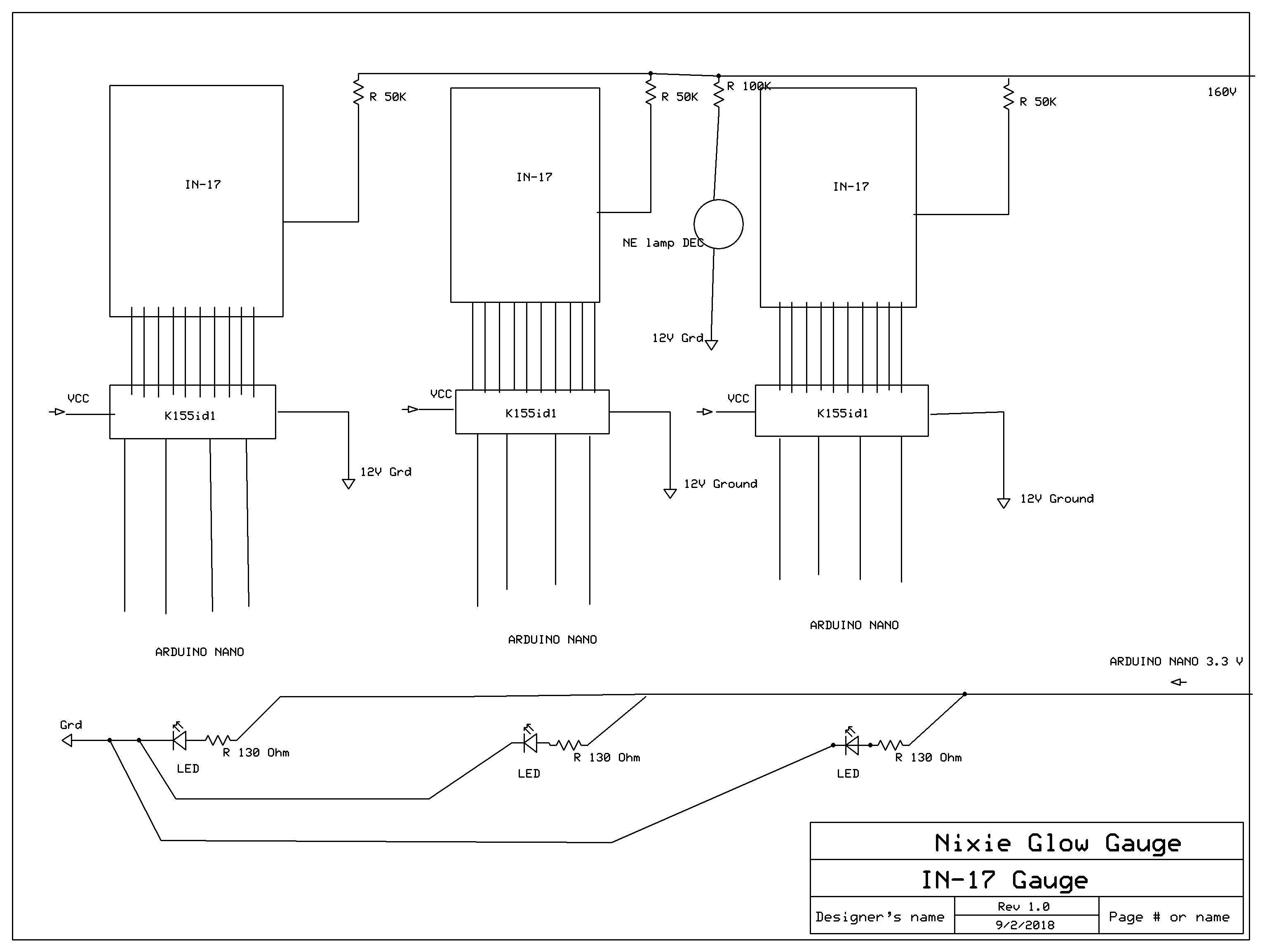
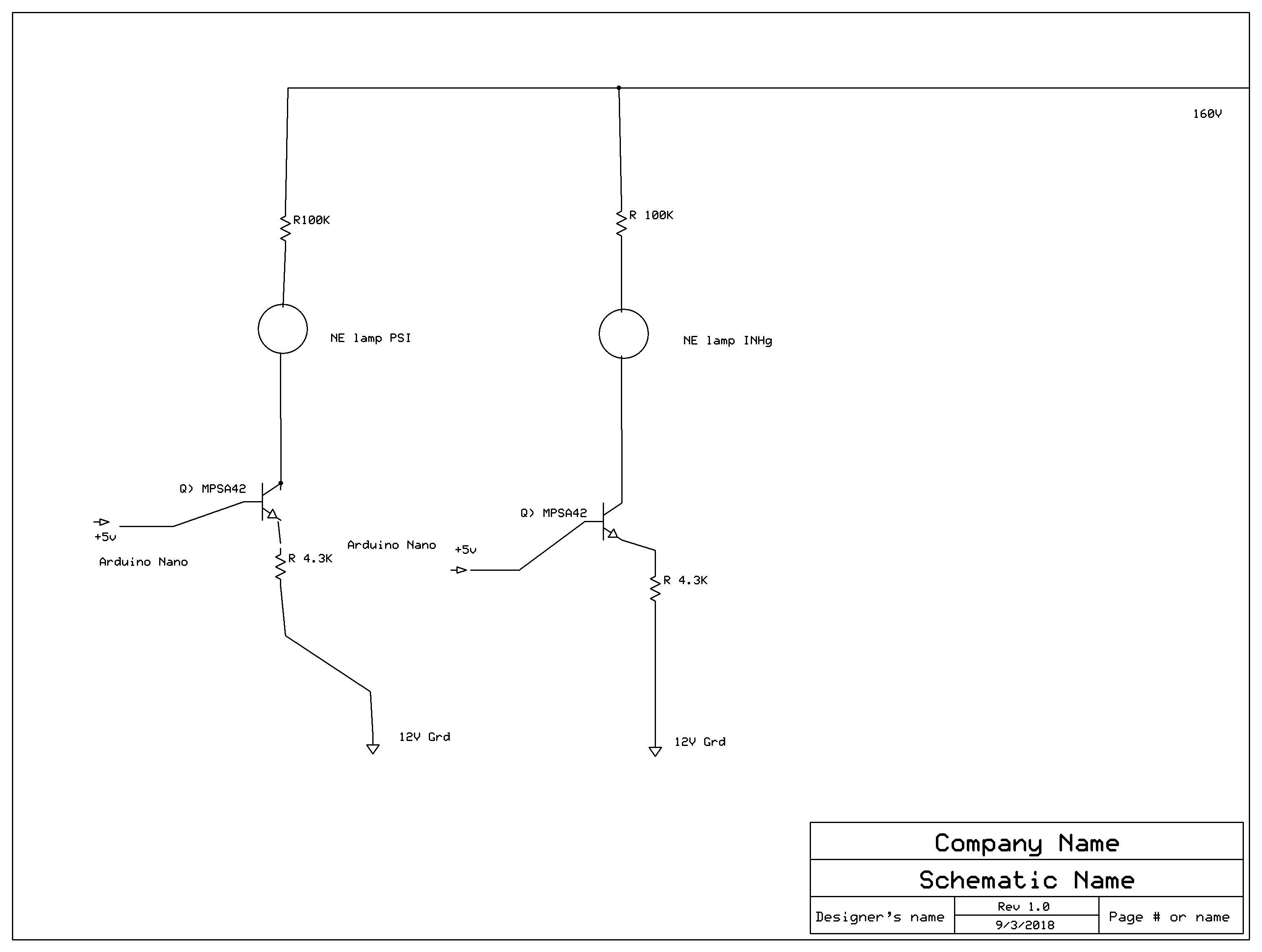
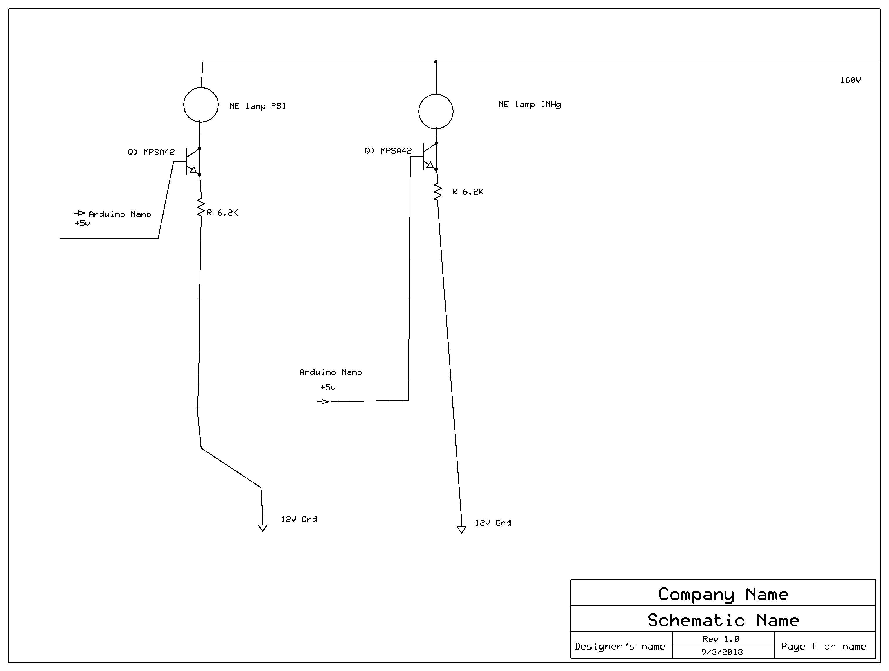
The schematic is for a Nixie boost gauge. Using IN-17 Nixies, and an Arduino Nano. The second schematic is for two NE lamps for Boost and vacuum. The NE lamp on the first schematic is the decimal place.

gregebert
Sep 3, 2018, 7:45:52 PM9/3/18
to neonixie-l
I noticed a couple items
1. The 2 transistors should have a resistor in the emitter or base to limit the base current; as it's drawn, the base-current will be limited by the output current of the Arduino. If you know what the current of the neon lamp should be, you can use an emitter resistor to make a constant-current driver. For example, if you want 1mA of current in the bulb, use 4.3K
2. There are a few LEDs that appear to be connected in-series and driven from 3.3V. An LED has a typical voltage drop of around 2V, so they probably wont light. Use a series resistor for each LED, and drive each resistor+LED from 3.3V. A 130 ohm series resistor will give you about 10mA.
Thomas Kummer
Sep 3, 2018, 9:48:32 PM9/3/18
to neonixie-l
gregebert
Sep 4, 2018, 12:06:09 AM9/4/18
to neonixie-l
For the LEDs, yes
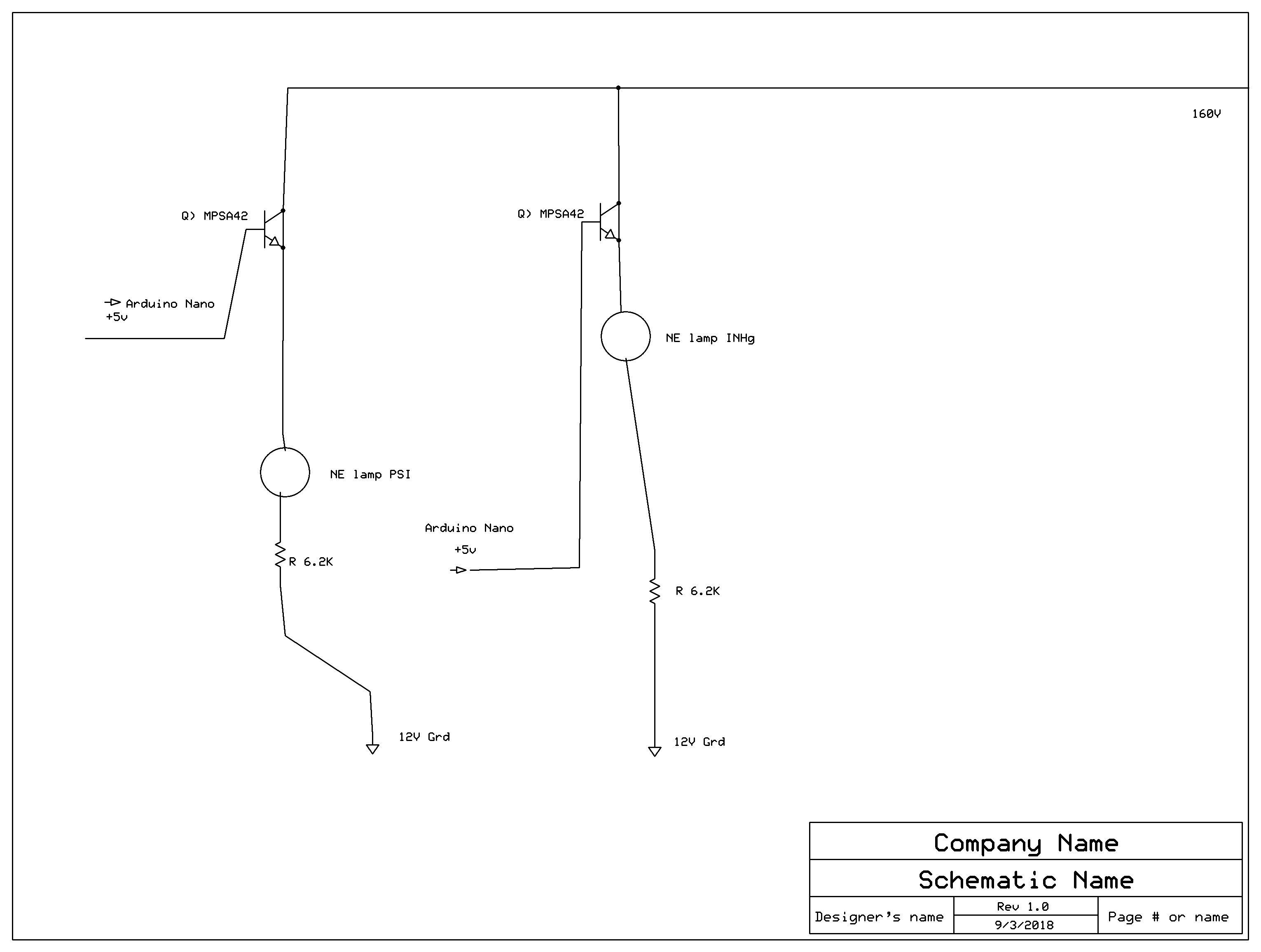
For the neon bulbs, remove the 100K series resistor. The transistor is a current-limiter. I took a wild guess at the operating current being 1mA; check the datasheet for DC operation. Be aware that neon bulbs wont last as long on DC vs AC, roughly 60% lifetime per datasheet.
If you have 2 extra pins on the arduino, you can run the neon bulbs on AC with 2 additional transistors + resistors. If that's desirable for you, go back to your original design and make a few changes:
1. 160 VDC --> 100K resistor --> NPN transistor collector. Instead of 2, you will need 4. Note that the neon bulb is NOT connected in-series.
2. Arduino_output --> 10K resistor --> NPN transistor base
3. Connect 1 neon bulb terminal to NPN collector
4. Alternately turn the NPN devices on at 50% duty cycle. This will drive an AC square-wave on the neon bulbs.
Thomas Kummer
Sep 4, 2018, 12:32:48 AM9/4/18
to neoni...@googlegroups.com
I’m out of pins on the Arduino Nano, unless I want to use shift registers. Which I really don’t as they would take up more circuit space. The Neon lamps require .7Ma and have a life expectancy of 20,000 hours AC so 12,000 hours DC, that’s longer than the IN-17 Nixie tube which is ~7,000hrs. This isn’t too big of a problem since the average person puts 13,000 miles on their car per year assuming average speed of 35mph that’s 372hrs of driving per year so by my estimate the tubes could last 18years, provided their protected from vibration.
So to run them on DC just remove the 100k resistors and put maybe a 50k resistor on the emitter?
Sent from my iPhone
--
You received this message because you are subscribed to the Google Groups "neonixie-l" group.
To unsubscribe from this group and stop receiving emails from it, send an email to neonixie-l+...@googlegroups.com.
To post to this group, send email to neoni...@googlegroups.com.
To view this discussion on the web, visit https://groups.google.com/d/msgid/neonixie-l/7ea0a037-56c5-4cf0-8915-4d4c58d1b4d3%40googlegroups.com.
For more options, visit https://groups.google.com/d/optout.
Thomas Kummer
Sep 4, 2018, 12:36:26 AM9/4/18
to neoni...@googlegroups.com
Sorry I meant 5k resistor.
--

Дмитрий Шевченко
Sep 4, 2018, 7:13:35 AM9/4/18
to neoni...@googlegroups.com
For arduino nano you may be interested:
https://groups.google.com/forum/#!topic/neonixie-l/2p5bFReY7ko
вт, 4 сент. 2018 г. в 7:36, Thomas Kummer <tmkumm...@gmail.com>:
> To view this discussion on the web, visit https://groups.google.com/d/msgid/neonixie-l/D135E705-1ED2-4F8A-9585-EDA4F3D8648F%40gmail.com.
https://groups.google.com/forum/#!topic/neonixie-l/2p5bFReY7ko
вт, 4 сент. 2018 г. в 7:36, Thomas Kummer <tmkumm...@gmail.com>:
gregebert
Sep 4, 2018, 2:06:13 PM9/4/18
to neonixie-l
The value of the emitter resistor is easy to calculate:
Re = (Arduino Output voltage - 0.7) / Bulb current
If the Arduino puts out 5V (are you sure it isn't 3.3 ?), and you want 0.7mA, Re is 6140 ohms; I think the nearest standard value is 6.2K
Thomas Kummer
Sep 4, 2018, 2:45:38 PM9/4/18
to neonixie-l
Yes, the Arduino only has one 3.3V output pin, and I am using that for the LEDs the rest are all 5V
Thomas Kummer
Sep 4, 2018, 2:54:45 PM9/4/18
to neonixie-l
On Tuesday, September 4, 2018 at 2:06:13 PM UTC-4, gregebert wrote:
Thomas Kummer
Sep 4, 2018, 3:00:28 PM9/4/18
to neonixie-l
By the way I really appreciate all the help you've been, and when I get this project up and running I will send you a gauge, on me.
On Tuesday, September 4, 2018 at 2:06:13 PM UTC-4, gregebert wrote:

Mark Moulding
Sep 4, 2018, 3:17:29 PM9/4/18
to neonixie-l
Instead of using a Nano, have you considered just using the ATMega328 chip by itself? I do this all the time for various projects. You can purchase the DIP-package chip pre-programmed with the Arduino bootloader - just add a crystal and use a TTL-level USB-serial converter and you're in business. (Just use the regular Arduino IDE - such as it is...). The whole chip will run just fine off 5 volts, removing any 3.3V interfacing difficulties.
I looked around a little, and couldn't find the surface-mount chip Atmega328P-AUR (T-QFP package) pre-programmed with the loader, but it's not very difficult to use AVRDude and a serial programmer ($7 or so on eBay) to burn the loader, then you're all set. I *completely* understand the space constraint you're facing, although your available depth can be pretty large (at least 2 inches); using the surface mount might make sense for this.
~~
Mark Moulding
Mark Moulding
Thomas Kummer
Sep 4, 2018, 3:27:38 PM9/4/18
to neonixie-l
On Tuesday, September 4, 2018 at 2:06:13 PM UTC-4, gregebert wrote:
Thomas Kummer
Sep 4, 2018, 3:46:52 PM9/4/18
to neonixie-l
The Nano is 43.18mm by 18.54mm so it will fit perfectly into the gauge housing, the nano has everything I need (14) 5V digital pins 6 analog pins, though realistically I only need one or two and a 3.3V pin to run the LED's. And yes I plan on using depth of the gauge housing to my advantage, the Buck Regulator in the back then the Arduino Nano then the HV smd chip and then the Nixie board up front.
gregebert
Sep 4, 2018, 4:15:41 PM9/4/18
to neonixie-l
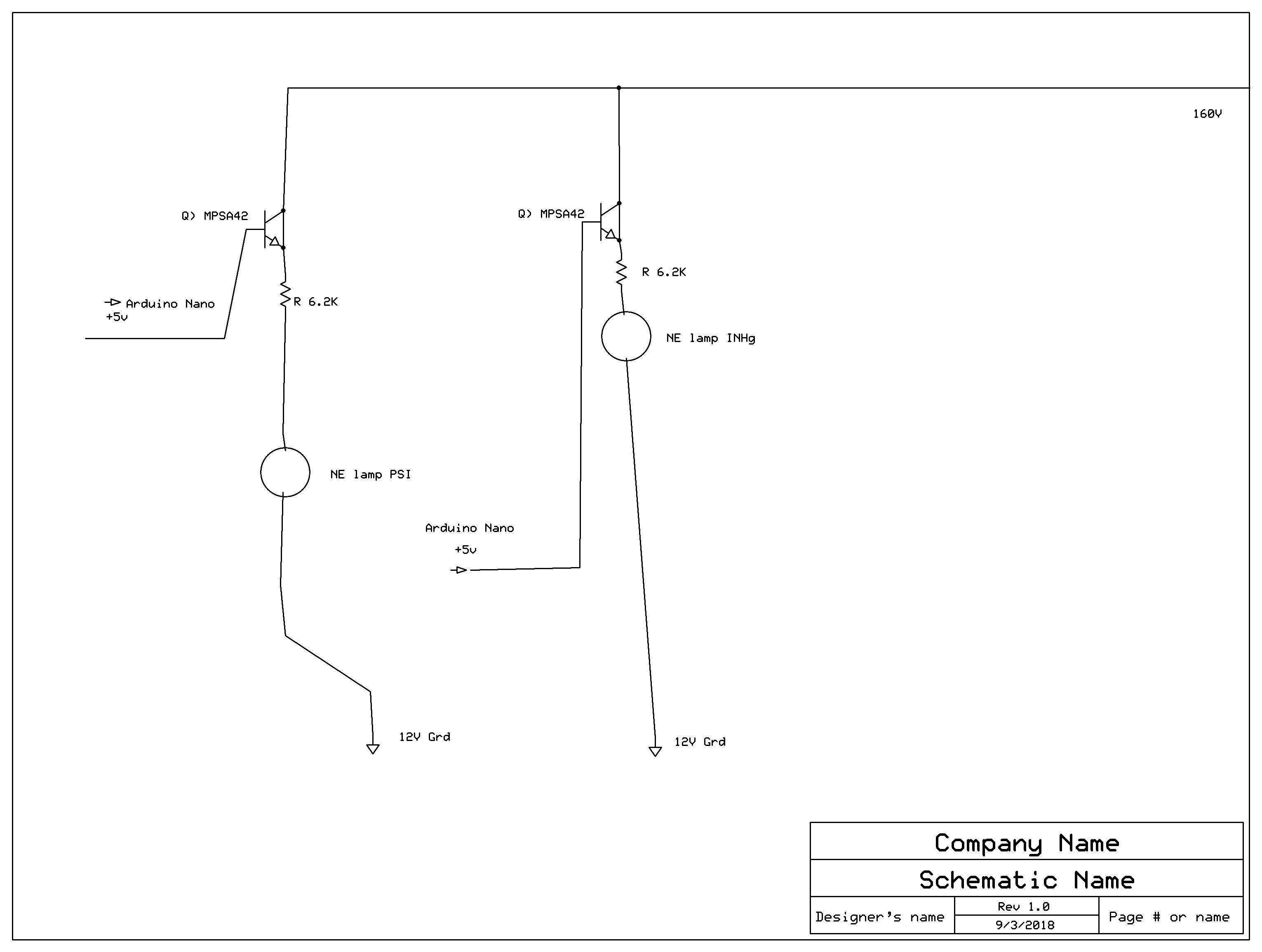
Schematic looks like it has some crossovers, etc. The path for the neon bulb is: 160 VDC --> Neon bulb ---> Transistor 'C' ---> Transistor 'E' ---> Emitter resistor ---> GND. Then connect the transistor base to your Arduino device.
If you are driving the LEDs directly from the Arduino, be careful with the current. I dont know how much current your LEDs require vs the output current of the pin.
For example, if you have 3 LEDs that run at 10mA each, that's a 30mA load for the Arduino, which is pretty high.
As an alternative, you could connect all 3 LEDs in series, drive from +12V, and use a current-limiter transistor similar to what you did for the neon bulbs. Just recalculate Re from the formula I posted earlier, and use 10mA and 3,3V. I get something like 260 ohms.
Lastly, since you are running on a 12V automotive supply, be aware that's a very nasty environment with all sorts of voltage spikes (alternator load-dump), dips (engine cranking), and even reverse-polarity (doofus giving your car a jump start has the cables backwards). It's especially bad for older vehicles that have mechanical voltage regulators. Even the method how you wire it will make a difference, depending upon what kinds of high-current devices share the wiring (fans, A/C compressor, starter, alternator, electric windows).
Thomas Kummer
Sep 4, 2018, 4:59:56 PM9/4/18
to neonixie-l
The 3.3V pin can handle up to 50mA of current, and supposedly more if you use the 5V input power pin rather than the 8V to 20V. I will be using 10mA LEDs I plan on using this setup, 12V car wire ---> buck converter ------> Arduino Nano 5V input pin. Like you said auto voltage has a lot of spikes and inconsistency, at least cars now have alternators instead of DC generators that would make the lights brighter when you gave the car gas lol. Now the SMD HV supply for the Nixies will be ran from the car wire, but I figure the capacitors can probably handle the voltage spikes.
Thomas Kummer
Sep 4, 2018, 5:17:14 PM9/4/18
to neonixie-l
gregebert
Sep 4, 2018, 7:49:07 PM9/4/18
to neonixie-l
OK, schematic looks right now
Large filter caps (> 100uF) by themselves wont solve the spike problem. You will need some series inductance (try 100uH), and some lower-value caps (0.1uF) in parallel because larger caps dont filter high-frequency noise very well. Also be sure to have a series diode from the +12V automobile power to protect against reverse-polarity. I recommend a fuse as well. As far as what L & C values to use for the filter, the values I guessed at get you a corner frequency of a few kHz. You might want to put a scope on your car and see what noise you get during engine-idle while the battery is charging; I'm guessing the alternator is the biggest source of low-frequency noise, but it could also be the ignition system. I've never looked; always been curious.
Plan on noisy signals from your sensors; there's all sorts of electrical noise under the hood. There's a lot of clever automotive engineers with many years of experience who have solved this problem, and hopefully published some technical papers.

GastonP
Sep 5, 2018, 8:42:16 AM9/5/18
to neonixie-l
I would also add some zener or transzorb, and would be wary of the engine start-up transient. There are several high value inductors being disengaged abruptly that can send a mighty pulse back. Depending on the age and state of the battery that pulse could be dangerous.

John Rehwinkel
Sep 5, 2018, 10:17:04 AM9/5/18
to 'Grahame' via neonixie-l
There are some nice integrated automotive transient and reverse polarity chips available these days that take care of a lot of that for you.
- John
--
You received this message because you are subscribed to the Google Groups "neonixie-l" group.
To unsubscribe from this group and stop receiving emails from it, send an email to neonixie-l+...@googlegroups.com.
To post to this group, send email to neoni...@googlegroups.com.
To view this discussion on the web, visit https://groups.google.com/d/msgid/neonixie-l/99d2c0fa-a9ed-4385-9c8e-ba81c5606eb2%40googlegroups.com.
Reply all
Reply to author
Forward
0 new messages