Looking for High side and Low side driver suggestions
208 views
Skip to first unread message

Richard Scales
May 20, 2021, 12:21:49 AM5/20/21
to neonixie-l
I am trying to learn about multiplexed displays (I thought it was about time I had a go at this) and I believe that I understand the basics - in as much as it requires the switching of the required anode as well as the required cathode (all of which are wired in parallel).
I understand that I can use something as simple as a single transistor for the cathode (low side) and a couple of transistors for the anode (high side).
Again, for the low side driver I could use any of the 'standard' shift register type drivers that we use in clocks such as an HV5622 (I appreciate that's way too many bits and I'm sure that there will be a smaller equivalent part available.
Specifically - is there such a part that I could use for the high side, ie switching the HV to the relevant anode?
I know that I could use a simple shift register (74595 for example) plus the transistors for a high side switch, I just wonder if there is a part which does all that in one package?
All pointers gleefully received.
- Richard

gregebert
May 20, 2021, 1:06:54 AM5/20/21
to neonixie-l
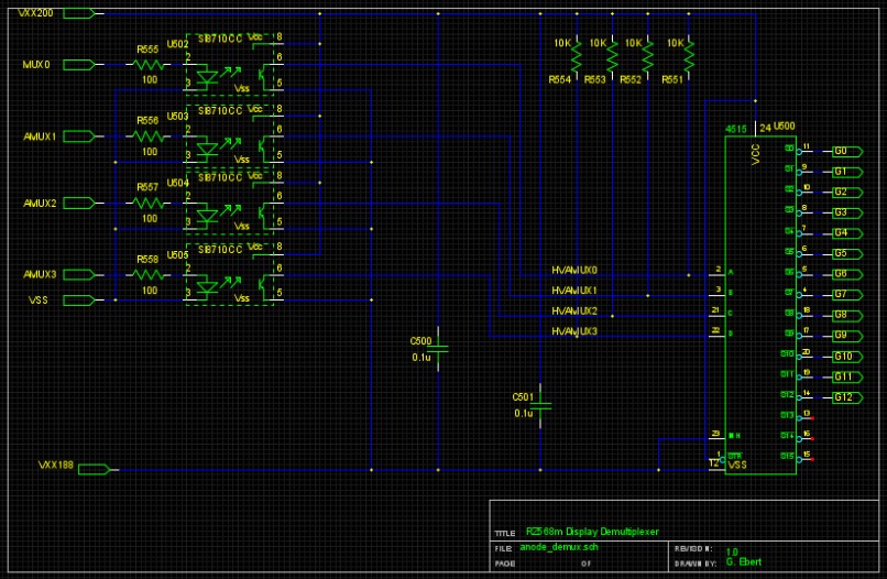
For my current clock project, I have a 9-segment / 13-character display that must be multiplexed, so I use a 4:16 decoder to drive PMOS anode-transistors on the high-side. The 4 bits into the DeMUX are piped thru digital isolators (SI8710), and driven from the FPGA. I use an isolated DCDC converter to provide a negative 12V supply relative to the anode supply (about 200V, because it's unregulated).
The low-side for the cathodes are just NPN current-limiters, also driven by the FPGA.

Paul Andrews
May 20, 2021, 11:02:47 AM5/20/21
to neonixie-l
The
HV5622 has open drain outputs, so the cathodes will be left to gradually float to whatever value they feel like. They probably won't do this fast enough to prevent ghosting and you don't really want them to float in a multiplexed clock anyway. I would suggest a push-pull chip for the cathodes, like the HV9808.
Richard Scales
May 20, 2021, 11:55:26 AM5/20/21
to neonixie-l
Thank you for that - I was looking at the HV513 which is push-pull and is rated for the higher voltage levels.
Being push pull - can I use those for the High side AND the low side?
- Richard

David Forbes
May 20, 2021, 12:58:44 PM5/20/21
to NeoNixie
Richard,
A million years ago, I designed a multiplexed Nixie clock using a 74141 cathode driver and two transistors per anode. It worked well.
Here's the user manual, with the schematic at the end. http://www.cathodecorner.com/nc620akitman.pdf
The only caveat is that capacitance in the Nixie tube wiring will cause ghosting which is dealt with by adding a time delay between turning off the cathode select and anode select, then turning on the next anode.
I didn't need any pull-mid resistors or other complications.
You can replace the 74141 with a couple SN75468 100V transistor arrays for the cathode drivers.
--
You received this message because you are subscribed to the Google Groups "neonixie-l" group.
To unsubscribe from this group and stop receiving emails from it, send an email to neonixie-l+...@googlegroups.com.
To view this discussion on the web, visit https://groups.google.com/d/msgid/neonixie-l/4e7d26e7-a9ff-463d-9493-794d8dab4943n%40googlegroups.com.
Paul Andrews
May 20, 2021, 2:37:57 PM5/20/21
to neonixie-l
I used a HV5523 to drive both - it is open drain. It worked fine, but I needed to clamp the cathodes to around 75V. The thing about a push-pull driver is that the push part is to clamp the cathodes, so whatever you are driving it will switch them between 0v and the voltage you want to clamp the cathodes at (e.g. 75V), so you couldn't use the same chip to directly clamp the cathodes and the control the anodes. At best you could use it control the PNP high side transistor.
Richard Scales
May 20, 2021, 11:45:11 PM5/20/21
to neonixie-l
Sorry, I mean using the same type of device to control the anodes AND the cathodes but but the actual same piece.
So, using an HV5523 (or perhaps multiple HV513, multiple because there are probably 8 cathodes (seven segment panaplex displays) and 16 Anodes (16 digits)) could be a way forward then.
Please could you let me know more about the need to clamp the cathodes to a certain voltage? (Exposing my real lack of understanding here!)
- Richard
Paul Andrews
May 21, 2021, 12:44:59 AM5/21/21
to neoni...@googlegroups.com
It might work if you use two for the anodes with Vpp set to 170V, and one for the cathodes with Vpp set to 75V.
The need to force things to a specific voltage is to make sure the transitions are fast to prevent ghosting or to prevent the off digits from glowing. When you move the power from the first anode to the next you will have to add a delay before you set the cathode states in order for the anode current in the first tube to drop to zero below the sustain voltage, otherwise the same cathode will light up in both tubes. Forcing the anode to ground means that delay can be smaller. Conversely, if the off cathodes aren’t clamped, it will take more time for them to rise from zero, which would cause the next tube to display the same digit as the first tube when you apply power to the anode.
At least, that has been my experience.
On May 20, 2021, at 11:45 PM, Richard Scales <ric...@scalesweb.co.uk> wrote:
Sorry, I mean using the same type of device to control the anodes AND the cathodes but but the actual same piece.
--
You received this message because you are subscribed to a topic in the Google Groups "neonixie-l" group.
To unsubscribe from this topic, visit https://groups.google.com/d/topic/neonixie-l/XWjWh-epHQc/unsubscribe.
To unsubscribe from this group and all its topics, send an email to neonixie-l+...@googlegroups.com.
To view this discussion on the web, visit https://groups.google.com/d/msgid/neonixie-l/edd2d9c8-bf41-43cf-af3b-546041d3fb0cn%40googlegroups.com.

martin martin
May 21, 2021, 8:52:52 AM5/21/21
to neonixie-l
You received this message because you are subscribed to the Google Groups "neonixie-l" group.
To unsubscribe from this group and stop receiving emails from it, send an email to neonixie-l+...@googlegroups.com.
To view this discussion on the web, visit https://groups.google.com/d/msgid/neonixie-l/7DEFE1A4-8DD8-460F-A023-4773641B6815%40gmail.com.
David Forbes
May 21, 2021, 2:13:35 PM5/21/21
to NeoNixie
Richard,
A single push-pull HV driver chip will not be able to drive a multiplexed display.
The reason is that it only connects each tube element to either 0V or 180V. It is not capable of leaving an element disconnected.
Richard Scales
May 25, 2021, 1:25:44 AM5/25/21
to neonixie-l
I think I am getting a little closer to understanding this all a little bit more. I have almost grasped the concept of clamping the cathodes at an intermediate voltage to aid switching them on and off in a timely manner in an effort to minimise ghosting.
Now it's all down to driver choice and chip count.
How about HV5812's? i have seen these used in multiplexing circuits - especially those where a group of say 6 nixies are split into two groups then the 20 bits from the driver are split into two groups of 10 bits, each group for one set of three nixies. that works just fine for nixies, not so good for a 16 digit device with cathodes common to all!
Regardless, it would be slightly more efficient than using a 32 bit device though ultimately an 8 bit device would suffice. Using the HV5812 I can see that I can just connect Vpp to 80V, job done. If I wanted to use HV513 (on the grounds that I only need 8 bits) would I then just clamp each cathode to 80V via a suitable resistor?
I guess I could simply not worry about it and waste the bits, I'm only ever going to do this once or twice and one of my design goals is to make this thing as small as possible.
For the high side i definitely need to switch 16 anodes so I need to employ a push/pull device - HV5523 will do that or I could perhaps use a couple of HV513's - again, the easiest thing to do would be to use a single HV5523 and waste half of the bits.
In an effort to home in on a solution - a single HV5523 for the 16 anodes and a single HV5812 for the cathodes (clamped to 80V) - have I missed anything crucial here?
I just feel that I should get a handle on this multiplexing thing. I now have a couple of different multi digit panaplex displays coming so I need to come up with a plan.
I have some ZM1500 (12 digits) on hand and some IGP-17 (16 digits) on their way.
... and I've not even started to think about the timing of all the various switching operations yet!
Thank you all for helping me with my education
- Richard
Paul Andrews
May 25, 2021, 3:11:18 PM5/25/21
to neonixie-l
The HV513 is push/pull. You can use it for the anodes and the cathodes. You set Vpp to 170V for the HV513 you are using to control the anodes. You set Vpp to 80V for the HV513 you are using to control the cathodes. Each pin can source or sink 20mA. You could even chain them all together, as far as the SPI interface is concerned.
You could use a resistor divider for the 80V, or you could use a zener voltage clamp. There should be next to no current flowing when the cathodes are at 80V (otherwise they would be lit).
gregebert
May 25, 2021, 6:54:18 PM5/25/21
to neonixie-l
I'm attempting my first multiplexed nixie project, in this case a 13-character / 9-segment display. Direct-drive is always my preference, but that is not an option due to the way the display is pinned-out.
I'm using an FPGA to control the multiplexing, so I've put a lot of software-controllable registers to set the time when anodes and cathodes are turned on and off to prevent ghosting. For my display, the blanking time is 20-100usec per the datasheet; I believe this is the time required to dissipate the charge from the ionized gas. I measured less than 10pF of capacitance between the various terminals, but I'm certain this is an underestimate of the actual charge that an ionized segment holds, so you really cant calculate the correct value of the bias resistor based on the time-constant from the blanking time and the measurable capacitance.
The anode-driver is a PMOS current-limiter that can be switched on or off, and the anode will be biased around +100V thru a 5meg resistor (two 10-meg resistors dividing the anode supply in-half). Cathodes are driven by NPN pulldowns that are current-limiting (3mA per datasheet). If I'm unable to eliminate ghosting by changing timer values, I will reduce the anode bias resistors.
Unfortunately I have 3 projects going right now (too many!!), so I wont have any progress update on this for awhile.

Bill Stanley
May 25, 2021, 7:19:35 PM5/25/21
to neonixie-l
Greg,
Would you mind listing the current limiting parts you use for both the PMOS high side and the NPN low side drivers?
Thanks;
-Bill-
gregebert
May 25, 2021, 7:48:15 PM5/25/21
to neonixie-l
PMOS is DMP45H150DHE ( https://www.diodes.com/assets/Datasheets/DMP45H150DHE.pdf ) , with 350 ohm source resistor
NPN is a PMBTA42DS (dual NPN) with a 1.3K emitter resistor. Base is driven from a 3.3V FPGA. ( https://assets.nexperia.com/documents/data-sheet/PMBTA42DS.pdf )
Richard Scales
May 25, 2021, 11:48:50 PM5/25/21
to neonixie-l
OK, I think I'm homing in on a solution.
Assuming a current of 0.5mA and a supply of 170V that suggests a series resistor of (170-125)/0.5 K = 90K, a world apart from the values that Bally are suggesting but I don't know their displays characteristics.
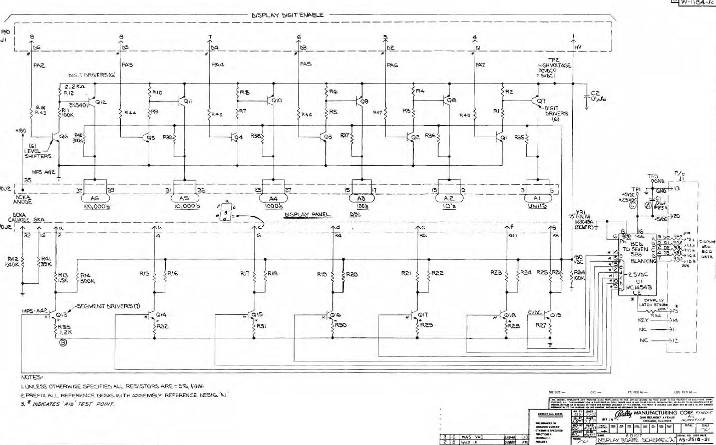
Assuming that I go with HV513 for high and low sides with the VPP's set accordingly there is then the whole series resistor thing to work out as I believe that peak currents can be higher in a multiplexed situation (did I read that right?). The circuit that I have seen for the Bally Pinball displays appear to be using a total of 1k5+1k2=2k7 though I have no knowledge of the specification of the displays that they were using.
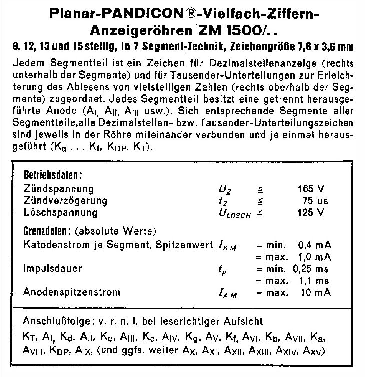
For the ZM1500 displays I have here - the specification suggests anode current between 0.4mA and 1.0mA with a maintaining voltage of 125V (assuming that I translated that correctly).
Assuming a current of 0.5mA and a supply of 170V that suggests a series resistor of (170-125)/0.5 K = 90K, a world apart from the values that Bally are suggesting but I don't know their displays characteristics.
Is there a suggestion that, depending on the 'on' time of the segment, the actual current could be set higher?
The same specification also lists an anode peak current of 10mA.
For now I'll plan to use something like 90K on each cathode to see how that goes - unless anyone can suggest that is hideously wrong?
- Richard
gregebert
May 26, 2021, 1:08:35 AM5/26/21
to neonixie-l
Interesting. Anodes and cathodes are biased to 80V. Also, note that the segment drivers use current-limiting (emitter resistors).
Paul Andrews
May 26, 2021, 9:00:17 AM5/26/21
to neonixie-l
I would guess that reason to set the 'off' voltage of both the anode and the cathode to the same values is to ensure that no current flows. Not sure why they picked 80V instead of, say, 0V for that. In the scheme I suggested, the anode would be pulled to 0V while the cathodes would be up at 80V. Not ideal, but the current flow should be minimal with that voltage difference.
My own experiments did not have a means to both push and pull the anodes/cathodes, so I relied on a pull down resistor for anode and a pull up resistor for the cathodes. I bread-boarded the design extensively before committing to it. Note that it is truly difficult to breadboard a multiplexed scheme. In my experience, the finished PCB will perform more reliably.
Richard, I think you can calculate the required current by multiplying the steady current by off-time/on-time. A ballpark figure would be Is * num-tubes. Then start with like half that :), but don't go above 10mA.
BTW, what does the note translate to? Connection sequence?

newxito
May 26, 2021, 10:00:20 AM5/26/21
to neonixie-l
Yes, from right to left with readable topview...
Richard Scales
May 26, 2021, 11:54:41 PM5/26/21
to neonixie-l
The note translates (according to Google) to:
Each segment part is assigned a character for decimal scan (to
the right below the segments) and for thousands of subdivisions to facilitate
the reading of multi-digit numbers (right above the segments). Each segment
part has a separately removed anode (Al, Ali. AIM, etc.).
Corresponding segments of all segment parts, all decimal place or thousands of subdivision signs are connected in the tube and each once led out (Ka Kl. KDP, KT).
- Richard
Dekatron42
May 27, 2021, 2:57:18 AM5/27/21
to neonixie-l
There's more data on the ZM1500 here: https://frank.pocnet.net/other/Valvo/Valvo_Anzeige_1974_1.pdf
You can also read about calculators using it here: https://worldradiohistory.com/AUSTRALIA/ETI-Australia/70s/ETI-1973-07.pdf
/Martin
newxito
May 27, 2021, 3:50:12 AM5/27/21
to neonixie-l
Just ordered some of these ZM1500. My project backlog is getting bigger and bigger. Maybe I should switch from waterfall to agile :-)
Richard Scales
May 27, 2021, 2:16:36 PM5/27/21
to neonixie-l
I know what you mean about project backlog - so many projects - so little time!
Almost every time I see a new retro display device I feel the urge to make it display time and stuff!
I have monster IN-28 boards, EL displays and Pinball reels all waiting to tick....
- RIchard
Reply all
Reply to author
Forward
0 new messages