Scope Clock SC200C
386 views
Skip to first unread message

Gary Kaufman
Oct 18, 2021, 7:53:06 PM10/18/21
to neoni...@googlegroups.com
I've been unsuccessful in reaching David Forbes, so thought I would
ask the group for help.
Many thanks in advance!
- Gary
My SC200C has been "unhealthy"
for a while now, and I'm trying to get it running properly.
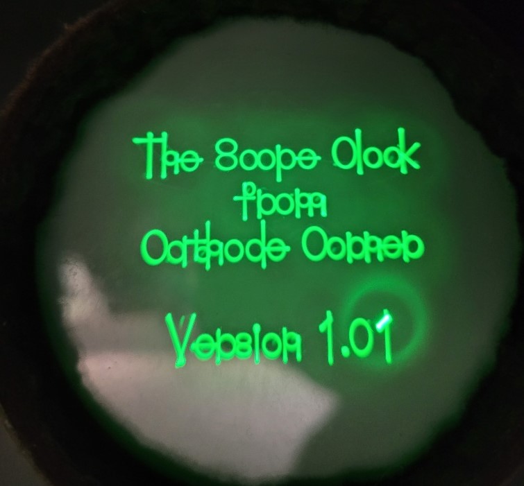
I've now got a stable, but scrambled display (see pic's). I think I have a problem with the shape generators but would appreciate any help or suggestions you could offer.
I've now got a stable, but scrambled display (see pic's). I think I have a problem with the shape generators but would appreciate any help or suggestions you could offer.
I've swapped the 74HCxx parts
with no improvement.
Many thanks in advance!
- Gary

J Forbes
Oct 18, 2021, 9:01:07 PM10/18/21
to neonixie-l
David's on a trip right now, he might answer when he gets back?

Toby Thain
Oct 18, 2021, 9:08:00 PM10/18/21
to neoni...@googlegroups.com, Gary Kaufman
On 2021-10-18 7:53 p.m., Gary Kaufman wrote:
> I've been unsuccessful in reaching David Forbes, so thought I would ask
> the group for help.
>
> My SC200C has been "unhealthy" for a while now, and I'm trying to get it
> running properly.
>
> I've now got a stable, but scrambled display (see pic's). I think I
> have a problem with the shape generators but would appreciate any help
> or suggestions you could offer.
>
I know this isn't helpful at all, but I have to admit I find this
> I've been unsuccessful in reaching David Forbes, so thought I would ask
> the group for help.
>
> My SC200C has been "unhealthy" for a while now, and I'm trying to get it
> running properly.
>
> I've now got a stable, but scrambled display (see pic's). I think I
> have a problem with the shape generators but would appreciate any help
> or suggestions you could offer.
>
accidental font quite charming.
Graphics bugs are the best bugs.
Are there schematics, source code etc we can access?
--T
> I've swapped the 74HCxx parts with no improvement.
>
> Many thanks in advance!
>
> - Gary
>
>
> You received this message because you are subscribed to the Google
> Groups "neonixie-l" group.
> To unsubscribe from this group and stop receiving emails from it, send
> an email to neonixie-l+...@googlegroups.com
> <mailto:neonixie-l+...@googlegroups.com>.
> To view this discussion on the web, visit
> https://groups.google.com/d/msgid/neonixie-l/3d31cce2-541f-08e4-65ad-a30135319e86%40gmail.com
> <https://groups.google.com/d/msgid/neonixie-l/3d31cce2-541f-08e4-65ad-a30135319e86%40gmail.com?utm_medium=email&utm_source=footer>.
Gary Kaufman
Oct 18, 2021, 11:02:47 PM10/18/21
to Toby Thain, neoni...@googlegroups.com
The documentation is online at http://www.cathodecorner.com/sc200c.html
It is a somewhat amusing problem :)
I should say that it was working fine for several years prior to this
problem.
- Gary
It is a somewhat amusing problem :)
I should say that it was working fine for several years prior to this
problem.
- Gary
GEK
Oct 18, 2021, 11:06:29 PM10/18/21
to neonixie-l
That would be fantastic - I've tried emailing him directly, but perhaps I have the wrong email or am getting spam filtered.

Mac Doktor
Oct 19, 2021, 1:08:31 AM10/19/21
to neonixie-l
On Oct 18, 2021, at 7:53 PM, Gary Kaufman <geka...@gmail.com> wrote:I've now got a stable, but scrambled display (see pic's). I think I have a problem with the shape generators but would appreciate any help or suggestions you could offer.
Nah, that's just Cyrillic Neu Sans.
Terry Bowman, KA4HJH
"The Mac Doctor"
"The Mac Doctor"
"If only you could see what I've seen with your eyes."—Roy Batty, Blade Runner

Ian Vine
Oct 19, 2021, 2:24:11 AM10/19/21
to neoni...@googlegroups.com
From what I remember:
the characters are generated from circles, ellipses or lines which in turn are created using sun or cosine waveforms
To make a character the beam is blanked for certain parts eg C is a circle with a bit cut out.
Looks like the blanking is not working as you’ve got a lot of circles and ellipses there.
Looks cool though
Cheers
Ian V
On 19 Oct 2021, at 06:08, Mac Doktor <themac...@gmail.com> wrote:
--
You received this message because you are subscribed to the Google Groups "neonixie-l" group.
To unsubscribe from this group and stop receiving emails from it, send an email to neonixie-l+...@googlegroups.com.
To view this discussion on the web, visit https://groups.google.com/d/msgid/neonixie-l/3FBEDB26-E97C-44E2-B088-BDA7DAE4A020%40gmail.com.

Marcin Adamski
Oct 19, 2021, 2:30:00 AM10/19/21
to neoni...@googlegroups.com
Hi All,
I have just received reminder to purchase my ski pass for next season
and I really enjoy the shape of fives on it (see the picture). I always
thought that there was a reason for the Russians to use the inverted 5...
Cheers,
Marcin
I have just received reminder to purchase my ski pass for next season
and I really enjoy the shape of fives on it (see the picture). I always
thought that there was a reason for the Russians to use the inverted 5...
Cheers,
Marcin

Audrey
Oct 19, 2021, 2:31:00 AM10/19/21
to neoni...@googlegroups.com
The reason the soviets did that is cost saving. That looks cool though.
--
You received this message because you are subscribed to the Google Groups "neonixie-l" group.
To unsubscribe from this group and stop receiving emails from it, send an email to neonixie-l+...@googlegroups.com.
To view this discussion on the web, visit https://groups.google.com/d/msgid/neonixie-l/11742cb1-39c8-1bb3-71f8-115617d1c63f%40gmail.com.
Marcin Adamski
Oct 19, 2021, 2:36:42 AM10/19/21
to neoni...@googlegroups.com
nah, they were the precursors of the new trend! 😉
To view this discussion on the web, visit https://groups.google.com/d/msgid/neonixie-l/CAPDJQ6BD9-dWvJx5FGT%2BAvLq177bN2FqfAnLz7uo_O4UfkND0Q%40mail.gmail.com.

Adrian Godwin
Oct 19, 2021, 4:51:10 AM10/19/21
to neonixie-l
It always surprised me that the inverted 2 is used. The cost saving must be tiny, given that only the character itself is re-used (once it's had supports added it's probably unique) and it's only 1 of 10 characters.
To view this discussion on the web, visit https://groups.google.com/d/msgid/neonixie-l/a3e163e0-c674-ff05-3a64-169a9a708dbe%40gmail.com.

Bartek Ogryz
Oct 19, 2021, 7:28:03 AM10/19/21
to neonixie-l
What about "6" and "9" ;) ?
The cost may not be so tiny - think about all the preparations, that have to be made, to produce a digit (project, matrix for the cutter, etc.)
Bartek.

Tristan
Oct 19, 2021, 9:50:56 PM10/19/21
to neonixie-l
I agree. The blanking is not working and as a result the beam is also faintly visible as it moves quickly between the characters as well drawing the arcs. It would be a good idea to check the BLNK signal on a scope and at least see that is is toggling but my money would be on the analogue blanking section. Given the other side of the optoisolator in the blanking section is at a fairly high negative voltage potential (as this reduces the need for the deflection amps to handle higher voltages) you will need to be careful when probing around there but I would start by checking the voltages across C54 and C55 (as long as you are confident doing so safely with the HV potential to ground). The correct voltages aren't specified on the schematic but they will be based on the grid cutoff voltage of the tube. If you wanted to avoid probing while the clock is on I'd be inclined to shotgun replace that section starting with the power supply diodes, caps and Q13 and then U17 and finally the passives and see how you go.
- Tristan
Tristan
Oct 19, 2021, 10:04:24 PM10/19/21
to neonixie-l
Also the voltage between the cathode and the blanking section should be checked (I.e. the voltage across C51) and R65 and R67 should be checked (or potentially replaced along with C51 if shotgunning it). The rest of the high voltage supply appears to be working.
- Tristan
GEK
Oct 19, 2021, 10:42:53 PM10/19/21
to neonixie-l
Tristan -
Thanks for those hints. the BLNK signal is pulsing at 60hz, and I swapped Q13 without any change. I also socketed U17 (6N137) while waiting for a replacement to arrive. Removing U17 from the circuit leaves the display unchanged, so it does appear that the blanking circuit is the culprit.
I'll swap U17 once it arrives - and if that doesn't fix things start shotgunning the passives.
Thanks again for the guidance, very appreciated!
- Gary
Tristan
Oct 20, 2021, 1:19:58 AM10/20/21
to neonixie-l
Hi Gary,
That's a bit odd. While I'm no EE I would have expected that removing U17 would have blanked the display if the rest of the circuit was working correctly. It looks Q13 should be conducting without U17 fitted and the grid should become more negative with respect to the cathode to ensure cutoff. I think you may need to look at the D35-38 and C52 & C53.
- Tristan
GEK
Oct 20, 2021, 7:16:53 AM10/20/21
to neonixie-l
Will do, Hopefully parts will be here by Friday. I may try and shotgun D35-38 and C52-53 before then as I should have spares around here.
Finger's crossed!
- Gary

martin martin
Oct 20, 2021, 9:33:41 AM10/20/21
to neonixie-l
Here's a simple one
To view this discussion on the web, visit https://groups.google.com/d/msgid/neonixie-l/00c69936-4f04-4a88-8343-f2f7d860135fn%40googlegroups.com.

Terry S
Oct 20, 2021, 8:04:03 PM10/20/21
to neonixie-l
That may just be one of the worst PCB layouts I've ever seen.

liam bartosiewicz
Oct 20, 2021, 8:32:33 PM10/20/21
to neoni...@googlegroups.com
The acute-angle traces give it character
On Oct 20, 2021, at 5:04 PM, Terry S <tschw...@gmail.com> wrote:
To view this discussion on the web, visit https://groups.google.com/d/msgid/neonixie-l/39da8dc4-eb48-4815-b039-8974fdf50a95n%40googlegroups.com.

Nicholas Stock
Oct 20, 2021, 9:02:22 PM10/20/21
to 'Greg P' via neonixie-l
You can find them directly at Howard's website
A rudimentary display, but cheap if you want to go that way. I'll stick to circle generated graphics (ala Grahame's or David's clocks....). Each to their own.
To view this discussion on the web, visit https://groups.google.com/d/msgid/neonixie-l/9ED6F190-F6C7-4574-9740-DCB25FE0666E%40gmail.com.

Paul Andrews
Oct 21, 2021, 3:05:10 PM10/21/21
to neonixie-l
Hah yes. I have one of its brethren that is even more 'eclectic'.
GEK
Oct 25, 2021, 8:20:26 PM10/25/21
to neonixie-l
Ok, so I'm stumped (again)...
I have replaced D35-38, C52, C53, C54, C55, Q1, C51 and U17.
R67, F68, R69, R70 and R71 measure correctly in circuit.
I've confirmed pulsing on the BLNK- signal at 60hz
I've also swapped U5 (74HC74) and U4 (74HC151).
I've swapped the CRT.
Curiously I need to have the Bright potentiometer (R11) at maximum to get an image.
Could something in the High Voltage Supply be causing problems with the blanking?

gregebert
Oct 25, 2021, 10:34:34 PM10/25/21
to neonixie-l
I dont have the same exact scope-clock, but with mine the intensity, focus, and astigmatism adjustments all interplay with eachother. Mine uses an 8SJ31J tube, and there is a test-point where you can verify the HV is correct. It should measure 300V.
Tristan
Oct 25, 2021, 11:02:21 PM10/25/21
to neonixie-l
The brightness pot needing to be turned right up still suggests that you have a problem with grid voltage control. I'd expect to see some higher frequencies much higher than 60Hz on the BLNK- signal as well though. I'd be surprised if the problem was in the supply sections for the cathode or anode given that it is mostly working in your photo but there could be an issue with the specific section of the supply dedicated to the grid and it is referenced to the cathode. Although you have now replaced most of the potentially offending components unless you have an open winding on the transformer. You could check the resistance across pins 4,5 and 6 of the transformer. I'd expect them all to read fairly low.
Bartek Ogryz
Oct 26, 2021, 3:17:49 PM10/26/21
to neonixie-l
I'm not familiar with that project and that circuit, but based on my experience in CRT TV repairs, if you have a proper blanking signal, something must be wrong with HV as Tristan said.
Grid1 - negative voltage on this grid allows electrons to flow (brighter picture), 0V blocks them (darkness). This grid can be driven by the blanking signal,
Grid2 - is the screen grid, high voltage accelerates the electrons and brightens the screen. If that voltage is too high, it can "force" electrons to flow, regardless of the Grid1 voltage.
Chceck the main power supply first - if it's voltage is too high, all HV voltages will also be too high.
GEK
Oct 26, 2021, 11:40:54 PM10/26/21
to neonixie-l
Thanks everyone for the hints, I'll look more closely at the HV - I'm a bit shy about measuring as I don't have a meter that will go to -1300v for the bright.
- Gary
gregebert
Oct 27, 2021, 1:06:19 AM10/27/21
to neonixie-l
Most DMMs have 10Meg input impedance, so you can put a 10meg resistor in-series with your meter, and measure double the voltage. It wont be exact, but pretty close. If you really need an exact measurement, then measure a stable lower voltage without the resistor, then again with it. Dividing those 2 measurements will give you a ratio close to 2.0, and you can use that when measuring your high voltage.
GEK
Oct 27, 2021, 10:48:16 AM10/27/21
to neonixie-l
I probably do have a 10meg resistor down in my cellar, time to dig. I wasn't sure if I'd need to create an actual voltage divider with 2 resistors/ground wire so that's helpful. I'd hate to destroy a Fluke...
GEK
Oct 27, 2021, 10:39:19 PM10/27/21
to neonixie-l
I'm getting approximately:
Astig +124v
Focus/A2 -852v
Cathode/Bright -1210v
Grid -1262v
The manual suggests that the Brightness has about -1300v, focus about -900v and Astig +300v
I can adjust the Astig from 0 - 240 but the image is sharpest at 124v.
- Gary
Tristan
Oct 28, 2021, 12:16:34 AM10/28/21
to neonixie-l
Given how far you have gone I'd lift pin 2 of U17 (leaving it unconnected) and measure the grid voltage. Then connect PIn 2 of U17 to POS5D and measure it again. The voltage should be more positive with the pin connected to POS5D. That would answer one and for all if the grid control is functional. It would also help to know which CRT model you have.

John Rehwinkel
Oct 30, 2021, 9:31:12 AM10/30/21
to 'David Weiner' via neonixie-l
Most DMMs have 10Meg input impedance, so you can put a 10meg resistor in-series with your meter, and measure double the voltage.
Note that many resistors are rated at only 150V, and aren't suitable for high voltage service like this. There are, of course, resistors with sufficient voltage specifications, but they're less likely to be found in your junk box.
- John
GEK
Oct 30, 2021, 12:28:34 PM10/30/21
to neonixie-l
Success!!!
I really appreciate all of the help from Tristan and others. Nice to have my clock back.
Turns out the trace from blanking from pin 9 of the 74HC74 takes a very long route around the edge of the board in reaching pin 2 of U17 (6N137). There was a small defect in the copper trace that must have failed over time. I was checking the blanking signal at the 74HC74 and missed checking the final connection to the 6N137.
The point about resistor voltage ratings is a good one, I often work with tube gear where this is an issue.
The CRT is a 3RP1A btw. They've become pricey but fortunately seem to have a long lifespan.

Tom Harris
Oct 30, 2021, 6:17:51 PM10/30/21
to neoni...@googlegroups.com
Which is why you use a string of them in series for this sort of thing. With appropriate insulation, I saw glass tube used in a physics lab.
--
You received this message because you are subscribed to the Google Groups "neonixie-l" group.
To unsubscribe from this group and stop receiving emails from it, send an email to neonixie-l+...@googlegroups.com.
To view this discussion on the web, visit https://groups.google.com/d/msgid/neonixie-l/2E8D12B1-5167-497F-86D4-BADEF7428E3D%40mac.com.
Mac Doktor
Oct 30, 2021, 8:22:49 PM10/30/21
to neonixie-l
On Oct 30, 2021, at 6:17 PM, Tom Harris <celep...@gmail.com> wrote:Which is why you use a string of them in series for this sort of thing.
My old HV scope probe has a resistor in it that's several inches long. It's rated something like 40kV and several rings in front of the handle to prevent arc-over. Must be for checking the high tension in a TV set. I also have a small laser power supply that I bought as a kit at a hamfest around '93. The bleeder on it is almost as long.
Like all laser PS kits I've seen the design is rather dodgy. The power transistor is only a TO-220 and the kit included a flimsy snap-on heat sink that gets too hot to touch in about fifteen seconds. I asked the seller about it and he said not to worry as the transistor was running within its heat spec. Right. When I can smell a transistor from across the room it's probably too hot.
I retrofitted it with the most enormous vertical TO-220 heat sink I could find and even that got too hot to touch after a few minutes. Switching out the 0.5mW tube that came with the kit with a 0.25mW finally solved the problem.
With appropriate insulation, I saw glass tube used in a physics lab.
You can always fill the tube with transformer oil. Preferably the kind that doesn't have PCBs in it.
Terry Bowman, KA4HJH
"The Mac Doctor"
"The Mac Doctor"
Q: Should car stereo speakers be pointed to the rear for more thrust or up for more traction?
A. On long trips, the 20- to 30% improvement in gas mileage you might get with speakers pointing to the rear is certainly worthwhile. On the other hand, if you drive on snow or ice, the extra traction of speakers pointing upward gives you added control.
A. On long trips, the 20- to 30% improvement in gas mileage you might get with speakers pointing to the rear is certainly worthwhile. On the other hand, if you drive on snow or ice, the extra traction of speakers pointing upward gives you added control.
Don Lancaster
Toby Thain
Oct 30, 2021, 8:31:47 PM10/30/21
to neoni...@googlegroups.com
On 2021-10-30 12:28 p.m., GEK wrote:
> Success!!! I really appreciate all of the help from Tristan and others.
> Nice to have my clock back.
>
> Turns out the trace from blanking from pin 9 of the 74HC74 takes a very
> long route around the edge of the board in reaching pin 2 of U17
> (6N137). There was a small defect in the copper trace that must have
> failed over time. I was checking the blanking signal at the 74HC74 and
> missed checking the final connection to the 6N137.
>
> The point about resistor voltage ratings is a good one, I often work
> with tube gear where this is an issue.
Great achievement, everyone loves a happy ending. Are you going to post
> Success!!! I really appreciate all of the help from Tristan and others.
> Nice to have my clock back.
>
> Turns out the trace from blanking from pin 9 of the 74HC74 takes a very
> long route around the edge of the board in reaching pin 2 of U17
> (6N137). There was a small defect in the copper trace that must have
> failed over time. I was checking the blanking signal at the 74HC74 and
> missed checking the final connection to the 6N137.
>
> The point about resistor voltage ratings is a good one, I often work
> with tube gear where this is an issue.
a nice success screen pic?
--T
>
> The CRT is a 3RP1A btw. They've become pricey but fortunately seem to
> have a long lifespan.
> On Saturday, October 30, 2021 at 9:31:12 AM UTC-4 jrehwin wrote:
>
>> Most DMMs have 10Meg input impedance, so you can put a 10meg
>> resistor in-series with your meter, and measure double the voltage.
>
> Note that many resistors are rated at only 150V, and aren't suitable
> for high voltage service like this. There are, of course, resistors
> with sufficient voltage specifications, but they're less likely to
> be found in your junk box.
>
> - John
>
> --
> You received this message because you are subscribed to the Google
> Groups "neonixie-l" group.
> To unsubscribe from this group and stop receiving emails from it, send
> an email to neonixie-l+...@googlegroups.com
> <mailto:neonixie-l+...@googlegroups.com>.
> You received this message because you are subscribed to the Google
> Groups "neonixie-l" group.
> To unsubscribe from this group and stop receiving emails from it, send
> an email to neonixie-l+...@googlegroups.com
> To view this discussion on the web, visit
> https://groups.google.com/d/msgid/neonixie-l/c8a99ecd-860b-4bdc-a06e-237c6d3db4cen%40googlegroups.com
> <https://groups.google.com/d/msgid/neonixie-l/c8a99ecd-860b-4bdc-a06e-237c6d3db4cen%40googlegroups.com?utm_medium=email&utm_source=footer>.
GEK
Oct 31, 2021, 7:14:12 AM10/31/21
to neonixie-l
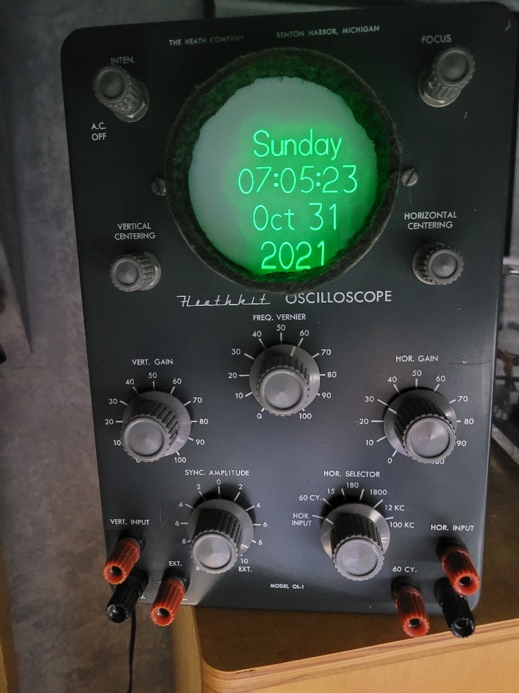
I still need to re-center the image after moving the clock, but it's working nicely again.
A huge thanks to everyone here!
- Gary

Bill Notfaded
Dec 27, 2021, 11:29:14 AM12/27/21
to neonixie-l
Terry-
Seeing your comment about PCB's made me remember a story about GE Electric in Schenectady NY. A mentor of mine in WAN engineering worked there years ago. He said they had huge pools filled with PCB's and techs would wade out into the pool in waders to tend to the pools. He said one day someone from GE environmental came around the office, where they had large transformers mounted on walls above desks that sometimes leaked and dripped. He said the pamper said their may be some side effects who exposure. One side effect was it chipped turn your hair white. My buddies hair was pure white... not silver.
Bill
Bill Notfaded
Dec 27, 2021, 11:31:08 AM12/27/21
to neonixie-l
Excuse the spell check phone post you get the idea lol!
Bill
Reply all
Reply to author
Forward
0 new messages