Tensile testing

Padmasanker S
Dear all,
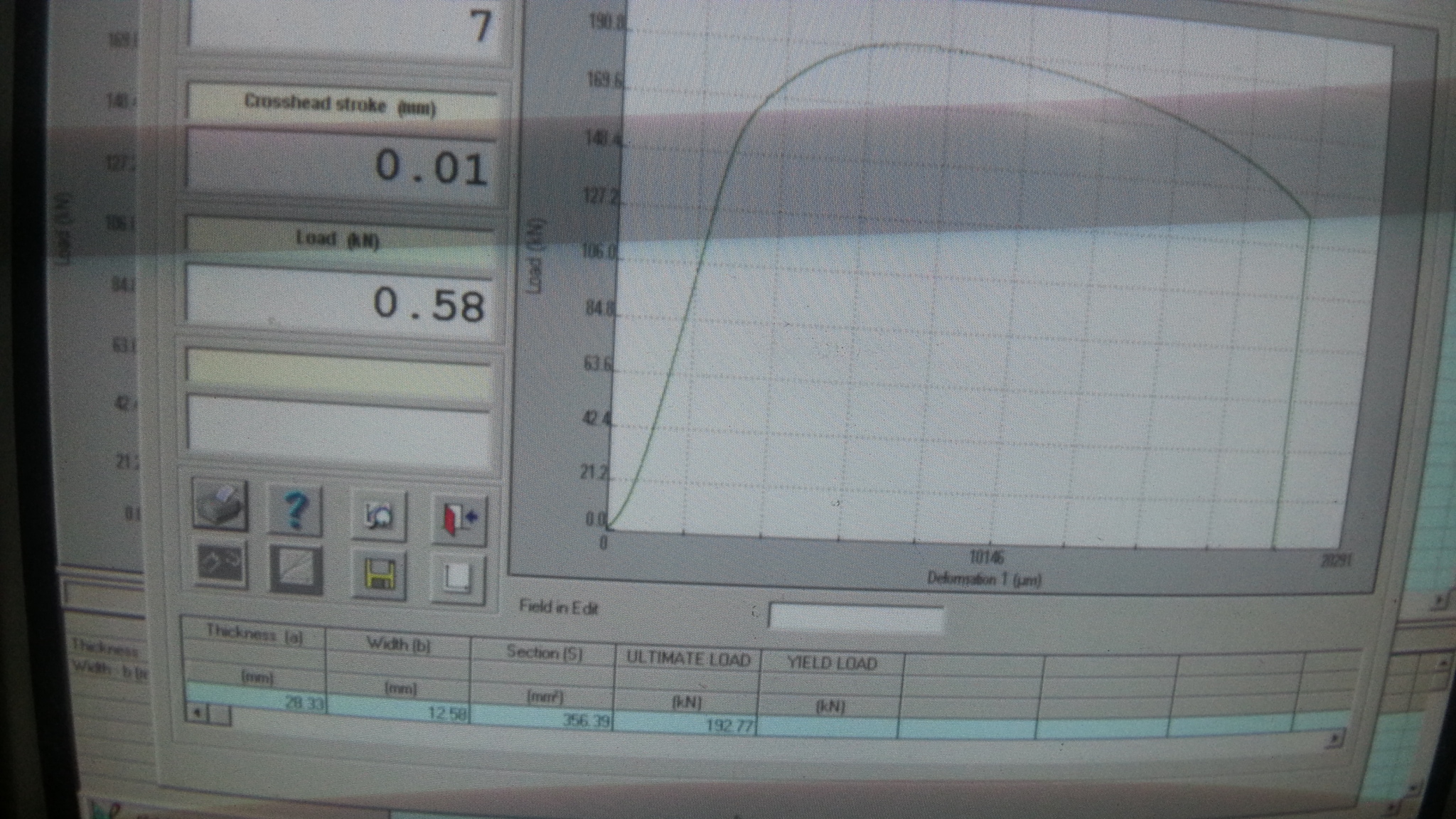
Please refer to attached stress -strain graph obtained during tensile testing of SA 106 Gr B pipe.
While performing tensile testing of SA 106 pipes for Div 1 vessels ,we were not getting yield point even though required tensile strength is obtained.
The specimen were taken in both transverse and longitudinal direction from half thickness.
Kindly share your experience in finding the root cause..
Please inform if any further details is required for clarity.
Best regards,
Padmasanker,
Quality coordinator,
Bilfal heavy industries ltd.

george....@gr.bureauveritas.com
That is because we define as Yield Point the stress at 0,2% permanent elongation
best regards
Dr. Georgios Dilintas
Authorized Nuclear Inspector
Authorized Inspector Supervisor
I&F REGIONAL TECHNICAL MANAGER
BUREAU VERITAS PIRAEUS - GREECE
Tel: +30 210 40 63 113 /4 /5
Fax: +30 210 40 63 118
Cell: +30 69 44 64 62 04
This message contains confidential information.
To know more, please click on the following link: http://disclaimer.bureauveritas.com

Harish Kannepalli
--
You received this message because you are subscribed to the Google Groups "Materials & Welding" group.
To unsubscribe from this group and stop receiving emails from it, send an email to materials-weld...@googlegroups.com.
To post to this group, send email to material...@googlegroups.com.
Visit this group at http://groups.google.com/group/materials-welding.
To view this discussion on the web visit https://groups.google.com/d/msgid/materials-welding/CAKDH8Gq%2BubEPKfFeaLTemr8ekcAO-KuOaddmKfrjwLEoDahXYQ%40mail.gmail.com.
For more options, visit https://groups.google.com/d/optout.

Mohanananthanarayanan KR
In order to get the 0.2% yield or proof stress, in the load vs extension curve take a point on x-axis at 0.2% of gauge length ( if 50 is GL then this point is 0.1mm on the x-axis ie along the extension). From this point draw a parallel line to the curve obtained by tensile test. This line would meet the curve at a point. Load corresponding to this is the 0.2% proof load and the stress based on this will give 0.2% Proof stress. Since some alloy steel unlike mild steel does not have a specific point of yield, this method is suggested for estimating the yield strength allowing a permanent yield of 0.2%. Software will have this but you have to verify that 0.2% of GL marked is taken for getting the value.
With warm regards
Mohan Ananthanarayanan
DGM QC VSSC
On Fri, 30 Oct 2015 20:28:50 +0400, Harish Kannepalli wrote
**Print this e-mail only if absolutely necessary. Save paper and keep India Green**
***The information contained in this e-mail message and / or attachments to it may contain confidential or privileged information. If you are not the intended recipient and received this e-mail in error, please notify us by reply e-mail / telephone and delete the message and attachments permanently. Thank you.***

Alan Denney
Just to endorse the statements below and to confirm that there is nothing unusual in finding that many grades of steel (and most other metals) do not have a defined yield point and we take the 0.2% proof stress as being ‘yield’ for design purposes. One exception is pipeline steels (many of which do not have clear yield point) but where we follow US practice and take as ‘yield’ the intercept with the stress strain curve corresponding to the 0.5% total strain. However if in doubt take the 0.2% proof stress as defined in Mohan Ananthanarayanan’s email below.
Alan
Alan Denney
AKD Materials Consulting Ltd
To view this discussion on the web visit https://groups.google.com/d/msgid/materials-welding/20151102042303.M38810%40vssc.gov.in.
For more options, visit https://groups.google.com/d/optout.
Padmasanker S
To view this discussion on the web visit https://groups.google.com/d/msgid/materials-welding/000d01d1156c%246cfd0eb0%2446f72c10%24%40denney1.freeserve.co.uk.
Alan Denney
Alan Denney
AKD Materials Consulting Ltd
From: material...@googlegroups.com [mailto:material...@googlegroups.com] On Behalf Of Pravin Nimbalkar
Sent: 16 November 2015 07:14
To: Materials & Welding <material...@googlegroups.com>
Subject: Re: [MW:23883] Tensile testing
Definitely
construct a straight line parallel to the initial linear portion of the stress-strain curve, but offset from it by e = 0.002 (0.2%.) The yield strength is taken as the stress level at which this straight line intersects the stress–strain curve.
Generally the yield point is observed in all carbon steel material.
The reason behind yield point is Cottrell atmosphere. Its related to how dislocation pinned in mild steel metals by carbon and nitrogen interstitials. These atoms distort the lattice shortly and there will be associated residual stress field surrounding the interstitials. This stress field relaxed by interestitail atoms diffusing towords dislocation. Once the dislocation has become pinned a small extra force is required to unpinn and the dislocation prior the yielding and produce upper yield point in stress-strain strain diagram. After unpinning dislocation are free to move in Crystal which results means lower yield point and material will deform in more plastic manner.
--
You received this message because you are subscribed to the Google Groups "Materials & Welding" group.
To unsubscribe from this group and stop receiving emails from it, send an email to materials-weld...@googlegroups.com.
To post to this group, send email to material...@googlegroups.com.
Visit this group at http://groups.google.com/group/materials-welding.

Pravin Nimbalkar
construct a straight line parallel to the initial linear portion of the stress-strain curve, but offset from it by e = 0.002 (0.2%.) The yield strength is taken as the stress level at which this straight line intersects the stress–strain curve.
Generally the yield point is observed in all carbon steel material.
Pravin Nimbalkar
Welding engineer
Bilfal heavy industries ltd