Breakout board for BeagleBone Black (BBB)

Jiří Procházka

Benjamin Balga
Hello,
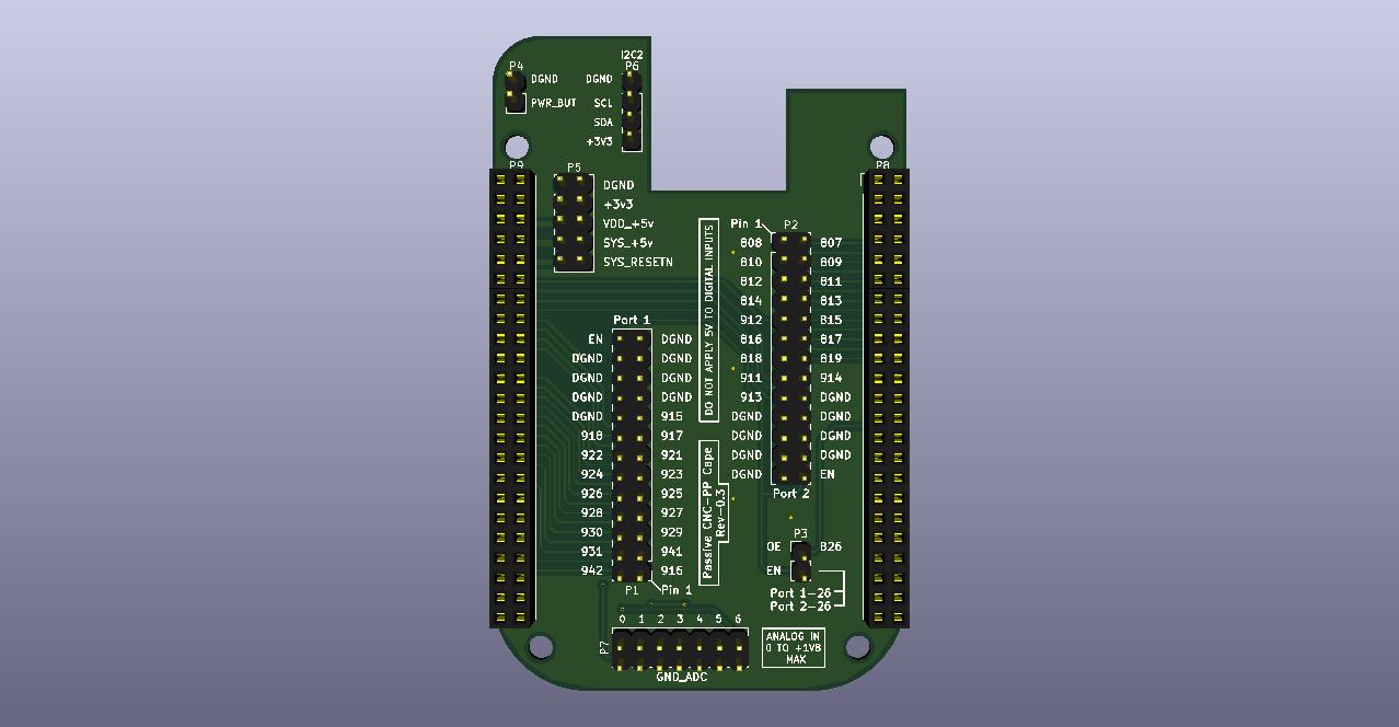
I you're not pressed by time, I might have something for you, in the "style" of the bbb_parport.
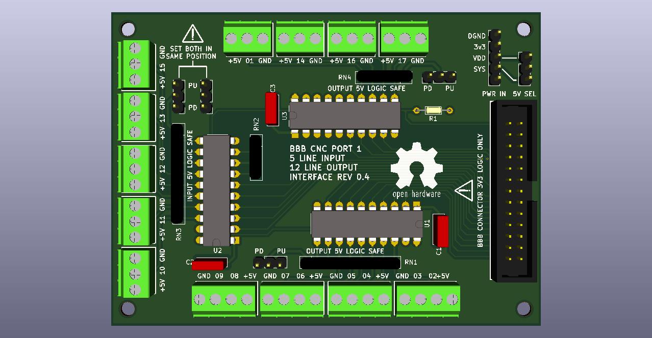
I rolled my own "DB25 cape" some months ago, works great, and I did a redesign last week to add more I/Os (you always need more :P ). It is a very simple cape with only level shifters for 5V@32mA I/Os routed to a 26-pin HE10 header. I removed the DB25 port that was integrated, but you can directly plug a HE10-like flat cable to DB25.
I don't know if any viable alternatives exists right now, at that time I couldn't find what I wanted. I read in another recent thread that Seed Studio is willing to design their own (but bigger and better).
"Issue" is, I need to design other stuff for it (breakout board to "big" screw terminals) before I can order it and test it, and as we're in confinement here right now (France), it could take a few weeks. I planned to share it here soon, but.. things happened :P
If you're feeling adventurous, I can give you the files for you to order some boards pre-assembled from JLCPCB (with all the SMD level shifters soldered, but no headers). Although I'm pretty confident that it will work no problem (the design is based on my first cape that works fine and only a few things changed), I can't guarantee it will work flawlessly. However, ordering 2 boards costs like 20€/$ without shipping (and no headers) so it's not very expensive (minimum order is 2 or 5 PCBs). You'll have to source and solder the headers yourself.
Otherwise, I was thinking of reselling some (with headers probably) after testing if anyone would be interested. But again, that will take time.
The project will be open-source, I'm just not too keen on releasing untested stuff just right now. But if people are interested, it could happen?
Cheers,
Benjamin
Jiří Procházka
Benjamin B (BBenj)
--
website: http://www.machinekit.io blog: http://blog.machinekit.io github: https://github.com/machinekit
---
You received this message because you are subscribed to a topic in the Google Groups "Machinekit" group.
To unsubscribe from this topic, visit https://groups.google.com/d/topic/machinekit/f1JJBTSNuVI/unsubscribe.
To unsubscribe from this group and all its topics, send an email to machinekit+...@googlegroups.com.
To view this discussion on the web visit https://groups.google.com/d/msgid/machinekit/457b4481-bc67-40e8-8502-3f10cb9e56ab%40googlegroups.com.

Rob M


John Dammeyer
Since I'm sitting around trying to figure out what to do with myself due to this COVID-19 I thought I'd put together a spreadsheet that shows how the pins are used on my Xylotex BBB_DB25_26 and how they are on the BBB-DB25-CNC-Cape.
There are issues with both of them. The Xylotex is no longer made and what they sell now is more like the CNC although I've not yet looked at what pins are used for what.
What is missing is the ability to access the CAN bus and no I2C pins brought out for external devices.
What's in the spread sheet is preliminary in the sense that I've not even assigned pins for the step/dir and inputs.
The Xylotex would have to lose the Home A in order to have a series string of limit switches. Ie. The Home switches for each axis can also be Limit at the Home position end. And then the other end a string of N/C switches in series.
Martin Berriman added an encoder MPG but his pins also interfere with some of the others on these two capes. Assigning the two inputs to free pins not used by some of the standard CNC signals but capturing the channel # and distance to step could be done from an SPI expansion I/O set of chips.
I don't know if the software polling of the encoder is fast enough for a spindle encoder but if power tapping was required then we definitely need to add that feature too.
All that says is that making up a BBB Break Out Board Cape should probably have either a second DB-25 to expand the I/O or just forget the DB-25 completely and create an actual cape that is also a Break Out board for a 4 Axis Mill. Complete with MPG support, Spindle Encoder Support, Home/Limit switches, CAN bus for say CANopen peripheral/motor expansion, RS232/485 for VFD control for spindle speed if the 0-10V output isn't available. And in fact this sort of BoB should have a 0-10V with DIR signal for the spindle.
It also needs to be able to deal with FAULT/ENABLE signals in order to disable/reset a drive that has faulted or for that matter an ESTOP in automatically sets the ENABLE false. That pin output should probably be available as both an active high and active low.
So much more I/O would be available if the Beagle did not use the HDMI LCD_DATA interface occupying much of the P8 connector. Looking at the NEXTION displays that are run from an RS232 port is one option. Or using SPI and I2C based signals for an LCD display that uses the LittlevGL library. I've been looking into that one with an ESP32.
But in many ways it would be easiest to keep the HDMI, slow as it is, with the MachineKit code inside the BBB. At least as a first step and just make it so the I/O on the LCD pins is available for expansion and a MachineKit version that uses Ethernet to something else for the standard AXIS type user interface.
John
You received this message because you are subscribed to the Google Groups "Machinekit" group.
To unsubscribe from this group and stop receiving emails from it, send an email to machinekit+...@googlegroups.com.
To view this discussion on the web visit https://groups.google.com/d/msgid/machinekit/CAGiu9V-%3DVQjip2P%2B9Nf7WBdY743QwYzuO0EM62XTjQn9yb67mg%40mail.gmail.com.
Rob M
John Dammeyer
I'm about halfway through modifying the cape PC board. Correct me if I'm wrong but because the BBB has internal flash it's expected that the OS and all run on that. That then frees up the pins on P8 marked MMC1_-- ?
I'm basing this off the charts from www.ExploringBeagleBone.com. I have both editions of the Derek Molloy's book.
I've added a CAN driver to the cape and I'm going to shift some pins down so the I2C pins can be brought to the header. What I'd like on the first connector is standard I/O and PWM out for spindle. Maybe even add the circuitry to create 0-10VDC. But there aren't enough pins on a standard parallel port to be able to do a spindle encoder or mpg. That's why I was looking at the RS232 and connecting to something like a MODIO or for that matter something similar that runs on CAN bus with CANopen protocol.
If you can afford it there are some pretty nice robust displays with CANopen or J1939 used for industry.
More as I work out what I'm trying to accomplish.
John
--
website: http://www.machinekit.io blog: http://blog.machinekit.io github: https://github.com/machinekit
---
You received this message because you are subscribed to the Google Groups "Machinekit" group.
To unsubscribe from this group and stop receiving emails from it, send an email to machinekit+...@googlegroups.com.
To view this discussion on the web visit https://groups.google.com/d/msgid/machinekit/2bfd00d0-0278-4eb4-b8ab-484205f74260%40googlegroups.com.
Benjamin Balga
To unsubscribe from this group and stop receiving emails from it, send an email to machi...@googlegroups.com.

ce...@tuta.io
Apr 4, 2020, 04:04 by ozzy...@gmail.com:
(I just hate for interested users to lose their enthusiasm.)
Cern.
>
> So you want someone to bounce ideas off my old noggin is pretty hard & dense.
>
> Cheers
> Rob
>
>
>
>
>
>
>
> website: > http://www.machinekit.io> blog: > http://blog.machinekit.io> github: > https://github.com/machinekit
> ---
> You received this message because you are subscribed to the Google Groups "Machinekit" group.
> To view this discussion on the web visit > https://groups.google.com/d/msgid/machinekit/2bfd00d0-0278-4eb4-b8ab-484205f74260%40googlegroups.com <https://groups.google.com/d/msgid/machinekit/2bfd00d0-0278-4eb4-b8ab-484205f74260%40googlegroups.com?utm_medium=email&utm_source=footer>> .
>
John Dammeyer
Hi Benjamin,
I can see that your layout was done for easy of routing with minimal feed throughs. Only once I plopped the CAN transceiver onto the schematic and used a copy of one of your resistors did I realize you'd used 0403 parts. I've soldered as small as 0602 by hand but not sure I want to try the smaller ones. Since 8 pins of the parallel port are outputs no matter what I'm thinking two SOIC 8 channel level translators are a more effective use of board space since the other 5 outputs also can use part of those.
My goal is to create a cape that has these which exceed what is available on the standard single parallel port
Outputs:
4 x STEP/DIR --> X,Y,Z and A
1 x Spindle STEP/DIR or PWM/DIR
1 x Enable (One signal Open Collector active high, one signal Open Collector low)
1 x Mist Coolant 12V relay driver
1 x Flood Coolant 12V relay driver
Inputs:
1 ESTOP input (Pin 10 on the DB-25)
5 Limit/Home (X,Y,Z,A Home + Combined Limit)
1 FAULT input
1 High Speed Encoder A,B and I
1 Low speed Encoder A,B for MPG.
I/O combinations.
1 x CAN bus (Tx/Rx for CANopen)
1 x UART (Tx/Rx for MODBUS or Nextion LCD Screen)
1 x I2C for LCD Touch Screen
1 x SPI for LCD Screen and I/O (includes 2 outputs for mux to Chip Select 4 devices).
This all has to exist on one board at a cost far lower than the MESA Raspberry interface board or there's just no point to it.
MachineKit has demonstrated that we can use the PRUs in the Beagle to deal with both spindle encoders and higher speed stepping.
So theoretically the above list implemented on a cape that has pluggable screw terminal connections to run a small CNC mill or Lathe with MachineKit and a USB hub for mouse, keyboard, USB stick (G-Code transfer) and USB based Pendant. If that sort of board could be built for under $100 then there's hope for the BBB.
And the SPI, I2C, CAN and UART allow expansion to an 800x600 LCD display, Keypad and things like VFD (ModBus) and Tool Changer (CANopen or MODbus).
And if someone wants more than that the better solution is a PC with full MESA expansion boards. If you are retrofitting some sort of mill that uses +/- 10V control with an encoder or resolver Jon Elson and others have LinuxCNC solutions that again are a better solution.
The market for BBB and 3D printers is gone. Other than as an exercise. I use a a Pi2B (I think) Octoprint and the Arduino Atmel based controller. It prints what I need. The BBB with Replicape will eventually end up controlling my POS Delta printer if I ever get the rest of the mechanical issues sorted out.
But past that. The opportunity for a BBB with a CNC cape is really that group of people who don't want CNC on their mill but do want a DRO and power feed. And if you suddenly plugged in an Ethernet connection to something running on the latest high tech hardware you have full Linux or MachineKit CNC.
If you want.
John Dammeyer
To unsubscribe from this group and stop receiving emails from it, send an email to machinekit+...@googlegroups.com.
To view this discussion on the web visit https://groups.google.com/d/msgid/machinekit/bde4bfae-a854-4c64-885f-d940001bab09%40googlegroups.com.
Benjamin B (BBenj)
John Dammeyer
Something along the line of this photo. Yes. Using connectors is more expensive rather than just screw terminals but if it's in an awkward place then it's much nicer to be able to unplug the connectors.
The board in this photo is a multi-purpose interface board. The two white molex connectors are the open collector outputs from the opto-isolators and run to the reset pin of the HP_UHU servo drives to reset them after a fault. The 4 terminal black plug in connector beside the regulator supplies 24V in and 5V out. I'm now using a small switching version of the LM7805 that doesn't need the heatsink.
On the left the green 4 conductor connector provides step/dir/enable and ground for the high speed opto isolated conversion to RS-422 for the STMBL drive or through the brown Molex connector a combination of RS422 and Open Collector to the Bergerda AC Servo drive.
And finally the 3 terminal green is the open collector output for FAULT from one of the two drives.
By mixing connectors and connector types it's possible to make something that is idiot proof (mostly for me) and can be pulled and replaced easily. I made 3 of these and the on in service at the moment has lots of jumpers where I had to change things as I learned what worked and didn't work with the PMDX-126 and the servo drives.
The far east PCB places do make it less expensive to make short run projects. The small board with the DB-25 and RJ-45 connectors just converts the DB-25 encoder from the Harmonic Drive or a Bergerda AC servo drive into the two RJ-45 cables needed for the STMBL AC Servo drive.
To view this discussion on the web visit https://groups.google.com/d/msgid/machinekit/CAGiu9V-twk8UWDJMfasNnbfsen397ny2kHo_OMOzT4q79-8kRQ%40mail.gmail.com.