Solid to SPH issues. Material cutting modeling.

Pavel Dybskiy

- (Figure 1) the Global internal energy (glstat "D") was noticeably higher than the sum of partial energies (matsum A,B,C).
- Total Energy was growing (driven by Internal energy growth) with External work = 0


l...@schwer.net
Have you tried the simulation without coupling, i.e. ICPL=0?
The newly formed chips are similar to debris and thus should be free from the base layer of FE. --len
ICPL EQ.0: Failure without coupling (debris simulation),
From: ls-d...@googlegroups.com <ls-d...@googlegroups.com> On Behalf Of Pavel Dybskiy
Sent: Wednesday, August 24, 2022 9:45 PM
To: LS-DYNA2 <ls-d...@googlegroups.com>
Subject: [LS-DYNA2] Solid to SPH issues. Material cutting modeling.
I'm modeling so called pendulum test where tip of the pendulum, a striker, cuts into the workpiece of interest.

Two types of workpiece representation were tried.
1) as an SPH part;
2) as a Solid FE part with Adaptive_Solid_to_SPH transition.
Known from literature (e.g. Mabrouki, et.al, 2008. “Numerical and experimental study of dry cutting ...) AL 2024 was used in order to test/verify the modeling approach.
Help is needed to interpret issues encountered.
1) When keyword Define_Adaptive_Solid_to_SPH was used with SPH coupled to solid FE (iCPL=1) from beginning(iOPT=0), then
- (Figure 1) the Global internal energy (glstat "D") was noticeably higher than the sum of partial energies (matsum A,B,C).
- Total Energy was growing (driven by Internal energy growth) with External work = 0
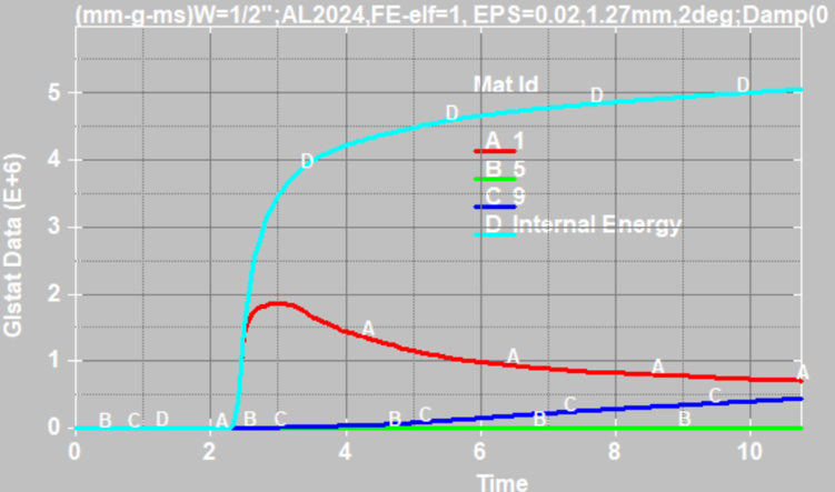
Figure 1. Energy
2) Workpiece reactions (Fy-horiz,Fz-vert) were significantly different, qualitatively and quantitatively, for SPH (Fig.2) vs FE-to-SPH representation and when iCPL =1 (Fig.3) vs iCPL=0 (Fig.4) were used in FE-to-SPH transition.


Figure 2. Pure SPH. Fy~ 150N


Figure 3. FE-to-SPH, iCPL=1. Fy~ 5000N


Figure 4. FE-to-SPH, iCPL=0. Fy~ +- 20000N
Best Regards
Paul Dybskiy
University of Windsor
--
You received this message because you are subscribed to the Google Groups "LS-DYNA2" group.
To unsubscribe from this group and stop receiving emails from it, send an email to ls-dyna2+u...@googlegroups.com.
To view this discussion on the web visit https://groups.google.com/d/msgid/ls-dyna2/8bf1d68e-2bf4-4cd4-a1e5-1f9e3322c136n%40googlegroups.com.

James M. Kennedy
Dear Pavel,
The *DEFINE_ADAPTIVE_SOLID_TO_SPH/DES keyword provides a simulation technique considering the effect of the debris since the failed solid elements are replaced with the particles. In this presentation, the results obtained using different options in *DEFINE_ADAPTIVE_SOLID_TO_SPH/DES were compared and the possibility to use this capability for real problems on concrete structures (*MAT_072R3) was discussed:
Tokura, S., and Niwa, K., "Evaluation of Debris Modeling Technique on Failure Simulation of Concrete Structures", 11th European LS-DYNA Users Conference, Salzburg, Austria, May, 2017.
http://www.dynalook.com/11th-european-ls-dyna-conference/concrete-penetration/
Recent LS-DYNA enhancements to air blast loadings:
Schwer, L.E., "New Keywords Related to Blast and Penetrations: A Few Simple Applications", 11th German LS-DYNA Forum, Ulm, Germany, October, 2012.
https://www.dynamore.de/de/download/papers/ls-dyna-forum-2012/documents/multiphysics-2-2
Some further information regarding your issues.
This inheriting of history variables would only apply to ICPL=1,IOPT=1 found on the keyword *ADAPTIVE_SOLID_TO_SPH entry. In this case, the failed solid turns to SPH and remains
coupled to remaining solids.
The converted SPH particles will couple only with the solid element that give birth to those particles. In this option, when solid elements are converted into SPH particles, the user can either
define the new material model (such as no failure or stronger failure criteria to ensure no further failure happens) or keep the same material model.
With this treatment the SPH particles are visible from the onset of the simulation. These embedded particles remain inactive and do not participate in contact until the parent solid element is eroded. Generally, contact with the solid elements is treated using one contact definition, while a second contact definition, typically, *CONTACT_AUTOMATIC_NODES_TO _SURFACE, is used to handle contact with the converted SPH particles. In the second definition, the slave side is made up of the SPH particles identified with SSTYP=3 in *CONTACT which references IPSPH defined in *DEFINE_ADAPTIVE_SOLID_TO_SPH.
I suggest you overlay time histories of stress for a solid element and the associated SPH particle(s) that take over after the solid fails. Also suggest using a high resolution output from elout for this purpose using *DATABASE_ELOUT, *DATABASE_HISTORY_SOLID, and *DATABASE_HISTORY_SPH. You will also need to write sphout (*DATABASE_SPHOUT), too, since elout does not have the SPH data.
This will give you the elout and sphout data which shows that the SPH particles indeed take their history variables from the host solid.
Attached (to your personal email) you will find an example wherein the SPH part has been given a different material ID to allow one to make the failure strain much larger than the failure strain of the host solid part.
R10 and later includes *MAT_ADD_EROSION criteria in SPH failure and that necessitates that different part IDs without the failure criterion be used for the adapted solid-to-SPH parts when ICPL=1,IOPT=1.
Sincerely,
James M. Kennedy
KBS2 Inc.
August 25, 2022
From: ls-d...@googlegroups.com [mailto:ls-d...@googlegroups.com] On Behalf Of l...@schwer.net
Sent: Thursday, August 25, 2022 8:33 AM
To: 'Pavel Dybskiy' <pdyb...@gmail.com>; 'LS-DYNA2' <ls-d...@googlegroups.com>
Subject: RE: [LS-DYNA2] Solid to SPH issues. Material cutting modeling.
Have you tried the simulation without coupling, i.e. ICPL=0?
The newly formed chips are similar to debris and thus should be free from the base layer of FE. --len
ICPL EQ.0: Failure without coupling (debris simulation),
From: ls-d...@googlegroups.com <ls-d...@googlegroups.com> On Behalf Of Pavel Dybskiy
Sent: Wednesday, August 24, 2022 9:45 PM
To: LS-DYNA2 <ls-d...@googlegroups.com>
Subject: [LS-DYNA2] Solid to SPH issues. Material cutting modeling.
I'm modeling so called pendulum test where tip of the pendulum, a striker, cuts into the workpiece of interest.

Two types of workpiece representation were tried.
1) as an SPH part;
2) as a Solid FE part with Adaptive_Solid_to_SPH transition.
Known from literature (e.g. Mabrouki, et.al, 2008. “Numerical and experimental study of dry cutting ...) AL 2024 was used in order to test/verify the modeling approach.
Help is needed to interpret issues encountered.
1) When keyword Define_Adaptive_Solid_to_SPH was used with SPH coupled to solid FE (iCPL=1) from beginning(iOPT=0), then
- (Figure 1) the Global internal energy (glstat "D") was noticeably higher than the sum of partial energies (matsum A,B,C).
- Total Energy was growing (driven by Internal energy growth) with External work = 0

Figure 1. Energy
2) Workpiece reactions (Fy-horiz,Fz-vert) were significantly different, qualitatively and quantitatively, for SPH (Fig.2) vs FE-to-SPH representation and when iCPL =1 (Fig.3) vs iCPL=0 (Fig.4) were used in FE-to-SPH transition.


Figure 2. Pure SPH. Fy~ 150N


Figure 3. FE-to-SPH, iCPL=1. Fy~ 5000N


Figure 4. FE-to-SPH, iCPL=0. Fy~ +- 20000N
Best Regards
Paul Dybskiy
University of Windsor
--
You received this message because you are subscribed to the Google Groups "LS-DYNA2" group.
To unsubscribe from this group and stop receiving emails from it, send an email to ls-dyna2+u...@googlegroups.com.
To view this discussion on the web visit https://groups.google.com/d/msgid/ls-dyna2/8bf1d68e-2bf4-4cd4-a1e5-1f9e3322c136n%40googlegroups.com.
--
You received this message because you are subscribed to the Google Groups "LS-DYNA2" group.
To unsubscribe from this group and stop receiving emails from it, send an email to ls-dyna2+u...@googlegroups.com
.
To view this discussion on the web visit https://groups.google.com/d/msgid/ls-dyna2/001501d8b887%244376e230%24ca64a690%24%40schwer.net.
Pavel Dybskiy
You received this message because you are subscribed to a topic in the Google Groups "LS-DYNA2" group.
To unsubscribe from this topic, visit https://groups.google.com/d/topic/ls-dyna2/1Vpp-jk6EfE/unsubscribe.
To unsubscribe from this group and all its topics, send an email to ls-dyna2+u...@googlegroups.com.
To view this discussion on the web visit https://groups.google.com/d/msgid/ls-dyna2/001501d8b887%244376e230%24ca64a690%24%40schwer.net.
l...@schwer.net
Paul –
1\ I know of no LS-DYNA to tool to discern “correctness” among models. Recall the useful quote from Professor George Box “All models are wrong, but some are useful.”
2\ At a minimum I suggest mesh refinement of the SPH elements, regardless of if you still pursue both approaches. Generally, MANY SPH elements are needed to replace one Lagrange solid, i.e. NQ=3 minimum.
3\ All such “mapping” of one solution to another involves error. Save yourself grief and stick to the all SPH approach.
4\ Developers get paid for new developments. They are the least capable of judging how effective such developments are for users.
--len
James M. Kennedy
.
To view this discussion on the web visit https://groups.google.com/d/msgid/ls-dyna2/000001d8b89b%2464760f10%242d622d30%24%40kbs2.com.
Pavel Dybskiy
From: Pavel Dybskiy <pdyb...@gmail.com>
Date: Thu, Aug 25, 2022 at 3:35 PM
Subject: Re: [LS-DYNA2] Solid to SPH issues. Material cutting modeling.
To: James M. Kennedy <j...@kbs2.com>

