Attempt to drive PXIe 6739 with labscript suite
157 views
Skip to first unread message

Padia Parth Kiranbhai
Nov 15, 2021, 12:42:50 PM11/15/21
to the labscript suite
Hi all,
I am new to labscript suite, so pardon me if I am mistaken.
I am new to labscript suite, so pardon me if I am mistaken.
To begin with labscript suite, we got RPi Pico and have flashed the drive with Prawnblaster configuration for pseduoclock implementation. Our goal is to control Ni PXIe-6739, however when defining acquisition rate on device initialization it gives an error that they can't be set because it has no analog inputs (which is indeed true). PXIe-6739 doesn't have any AI channels. How do I go about using labscript suite with PXIe 6739?
Best,
Parth

Chris Billington
Nov 15, 2021, 3:07:14 PM11/15/21
to labscri...@googlegroups.com
Hi Padia,
Analog acquisition is currently the only kind of acquisition labscript supports for NI DAQmx devices, so setting the acquisition rate only makes sense for devices that have analog inputs.
Simply omit the acquisition_rate argument from the initialisation, and you won't get the error.
If you are looking to do digital acquisition, unfortunately that's not supported at the moment. Implementing it would not be too difficult given it is very similar to analog input, but it seems few have had the need for it so far so nobody has put in the work yk add the functionality yet.
Hope that helps,
Chris
The information contained in this electronic communication is intended solely for the individual(s) or entity to which it is addressed. It may contain proprietary, confidential and/or legally privileged information. Any review, retransmission, dissemination, printing, copying or other use of, or taking any action in reliance on the contents of this information by person(s) or entities other than the intended recipient is strictly prohibited and may be unlawful. If you have received this communication in error, please notify us by responding to this email or telephone and immediately and permanently delete all copies of this message and any attachments from your system(s). The contents of this message do not necessarily represent the views or policies of BITS Pilani.
--
You received this message because you are subscribed to the Google Groups "the labscript suite" group.
To unsubscribe from this group and stop receiving emails from it, send an email to labscriptsuit...@googlegroups.com.
To view this discussion on the web, visit https://groups.google.com/d/msgid/labscriptsuite/e25a0933-63ed-4415-aeed-acaff13a5d81n%40googlegroups.com.
Padia Parth Kiranbhai
Nov 15, 2021, 4:28:14 PM11/15/21
to the labscript suite
Hi Chris,
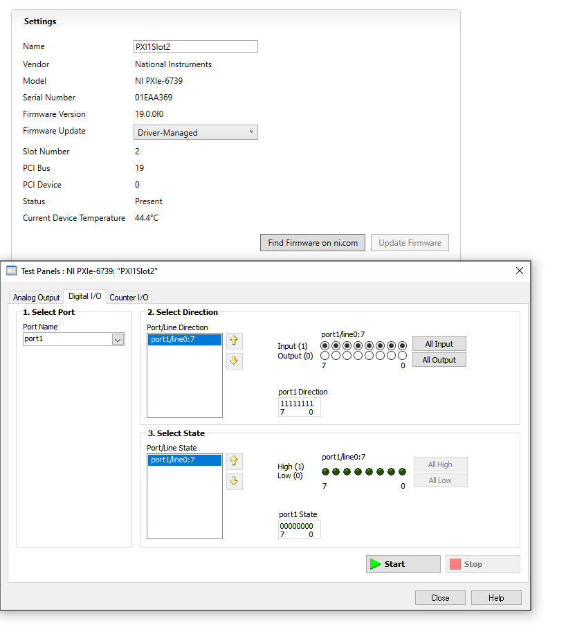
Thank you for the quick response. I omitted the acquisition parameter, but now I believe PyDAQmx doesn't recognize my clock. For PXIe 6739, there are 20 Digital I/O channels - 4 of them are buffered and rest of the 16 are static. I am connecting my clock to one of the static I/O but I get the attached error (along with the connection table script). Please guide me how to resolve this issue. Many thanks!
Best,
Parth
Chris Billington
Nov 16, 2021, 5:18:34 AM11/16/21
to labscri...@googlegroups.com
Hi Padia,
These non-buffered digital IO terminals have multiple names: they can be named either by their port and line number, or as a PFI terminal. But for specifying which terminal the clock is connected to, the NI DAQmx library requires the PFI name, and the port-and-line name doesn't work.
I see in the device pinout that port1/line0 corresponds to PFI0. Try replacing 'PXI1Slot2/port1/line0' with 'PXI1Slot2/port1/PFI0' for the clock terminal in your connection table, and you ought to have more luck.
Hope that helps!
Chris
To view this discussion on the web, visit https://groups.google.com/d/msgid/labscriptsuite/9e9a54b5-c695-4f47-91e3-3d9fadcc3571n%40googlegroups.com.
Message has been deleted
Chris Billington
Nov 17, 2021, 5:51:18 PM11/17/21
to labscri...@googlegroups.com
Hi Padia,
No, you shouldn't have to configure anything additional in NI MAX or otherwise - labscript should do all that. It is attempting to do so in the configuration of the analog task which results in the error you are seeing.
The remaining error you're getting is because the terminal name is not specified correctly. I'm sorry, this is my fault - I wrote it incorrectly in my previous email. It should be 'PXI1Slot2/PFI0', not 'PXI1Slot2/port1/PFI0'.
Hope your problem will be resolved after correcting that!
Regards,
Chris
On Thu, 18 Nov 2021 at 05:54, Padia Parth Kiranbhai <f2016...@alumni.bits-pilani.ac.in> wrote:
Hi Chris,Thank you for the suggestion. I tried it, but unfortunately I am getting the same error. I dug up a little bit on this and I have two questions to ask:1.) Do I need to explicitly configure my line1/port0 as a PFI channel on NI MAX, as you can see on the pinout page it says configure it to PFI or D I/O2.) On googling the error, the solution on the official page mentions that the sample clock might not be configured correctly, can it be because I didn't define acquisition rate parameter to initialize PrawnBlaster?This is just a guess, but as you can see in the error (attached) it uses the AO_task's WriteAnalogF64, however our PXIe doesn't have an analog input channel is that a problem? Is it possible to use a DO_task to write into the channel instead (sorry if it doesn't make sense, I am still understanding the workflow of the suite).As a matter of fact, if I use NI MAX UI to acquire my pseduoclock signal it works perfectly fine (same output as seen on runviewer).Best,Parth
To view this discussion on the web, visit https://groups.google.com/d/msgid/labscriptsuite/76cdbdd7-5270-460c-8d67-0e70a88af355n%40googlegroups.com.
Padia Parth Kiranbhai
May 12, 2023, 12:11:36 PM5/12/23
to the labscript suite
Hi all,
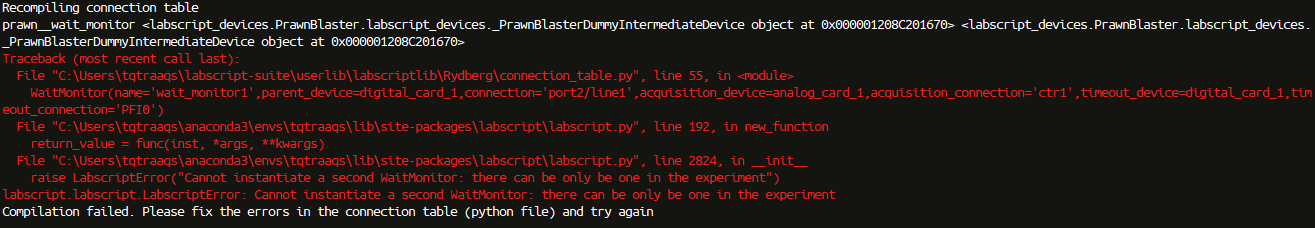
I am trying to add a wait-monitor to the connection_table (attached), however on compiling the connection_table on BLACS it throws an error (attached) stating that a second wait-monitor can't be instantiated. On tracing the wait-monitor code and printing the name of first wait-monitor it shows that there's already a wait-monitor object named 'prawn_wait_monitor'. We do use PrawnBlaster as our pseudo-clock, so I'm wondering if labscript is limited in defining a wait-monitor with PrawnBlaster or there's a quick work around?
Also as a sanity check, is it a good idea to share one clock-line from PrawnBlaster with multiple DAQ cards with clock mirroring (as done in the attached connection_table) or having independent pseudo-clocks for each card is more efficient? I have wired them in a single clock-line to make pseudo-clock triggering easier.

Philip Starkey
May 13, 2023, 1:02:20 AM5/13/23
to labscri...@googlegroups.com
Hi Padia,
Labscript only supports 1 wait monitor at a time. If you want to disable the automatic wait monitor created by the PrawnBlaster, you can pass use_wait_monitor=False as an extra keyword argument to the PrawnBlaster. E.g.:
PrawnBlaster(name='prawn',com_port='COM4',num_pseudoclocks=3, use_wait_monitor=False)
That said, is there a reason you want to use the NI Card as a wait monitor over the one in the PrawnBlaster? The PrawnBlaster should be more accurate and have a greater precision if it's being externally referenced.
Cheers,
Phil
To view this discussion on the web, visit https://groups.google.com/d/msgid/labscriptsuite/f485fb2f-58b6-45c9-85a3-af0f2092992cn%40googlegroups.com.
Padia Parth Kiranbhai
May 15, 2023, 3:50:39 PM5/15/23
to the labscript suite
Hi Phil,
Thanks for the quick response.
There's no particular reason to why I'm trying to setup waitmonitor on the NI card, I was simply following the wait monitor steps given in your thesis in section 5.1.7 and was planning to wire the hardware as Fig 5.11(b). After going through the PrawnBlaster's code, I realized that it has its own wait monitor and it seems it doesn't require a lot of wiring. However, wait monitor's initialization in PrawnBlaster class sets the timeout device as 'internal', I am wondering how do I wire an OR gate with external (not under labscript suite's control) trigger and timeout trigger connected to the Pseudoclock 0 trigger input (GPIO 0). Your comments are greatly appreciated!
Best,
Parth
Philip Starkey
May 16, 2023, 5:49:33 AM5/16/23
to labscri...@googlegroups.com
Hi Parth,
Aha, yep. My thesis was written before the PrawnBlaster was even conceived, so it's now a lot simpler if you are using it.
The timeout trigger for the PrawnBlaster wait monitor is handled internally by the PrawnBlaster firmware. When the PrawnBlaster enters a wait, it keeps count of how long it has been. If an external trigger is detected, it resumes. If it waits as long as the timeout, it also resumes by itself (without emitting any physical timeout trigger signal). So the internal timeout trigger and the external trigger are already OR'd together Bu default inside the firmware. You should just be able to wire your external trigger to the PrawnBlaster and everything will work.
Hope that helps, but if I've misunderstood something please let me know (a wiring diagram might also help me understand).
Cheers,
Phil
To view this discussion on the web, visit https://groups.google.com/d/msgid/labscriptsuite/aaa5d7c4-d776-4792-8531-c18fdf16a3e9n%40googlegroups.com.
Padia Parth Kiranbhai
May 17, 2023, 5:18:20 PM5/17/23
to the labscript suite
Hi Phil,
That's very helpful, thanks. I tried connecting external trigger directly to GPIO 0, but the code execution doesn't resume after sending a high pulse. The wait always ends after hitting the timeout (even if I send +5V signal to GPIO 0 during execution). I'm also setting the input,output pins (same as default) manually to avoid any confusion. Could you please provide more information if there's something else that needs to be setup? I am attaching the connection_table and shot file for review. The only wiring I've done for this instance is connecting external trigger to GPIO 0.
Best,
Parth
Parth

Philip Starkey
May 18, 2023, 7:25:37 AM5/18/23
to labscri...@googlegroups.com
Hi Parth,
Cheers,
The Raspberry Pi Pico FAQ suggests that 5v signals may damage the chip.
So it's possible that GPIO is broken given you stated you had tried a 5v signal too. Could you try using another GPIO (that you have never used before) with a 3.3v signal only? You can tell the PrawnBlaster to use that GPIO by specifying an additional keyword argument in_pins=[1,1,1,1] for GPIO 1 (for example)
If that still doesn't work, I would suggest debugging the PrawnBlaster behaviour without labscript, by closing BLACS, power cycling the prawnblaster, and programming a basic set of instructions in (over a serial connection) to test, as per the available commands here. That will tell us if it's an issue with the hardware or labscript/blacs.
Cheers,
Phil
To view this discussion on the web, visit https://groups.google.com/d/msgid/labscriptsuite/e9599c8f-d7f9-45a7-a729-71505e12c832n%40googlegroups.com.
Reply all
Reply to author
Forward
0 new messages