Can’t figure out how to optimize lens parameters to correct for distortion
89 views
Skip to first unread message

Dave Thorup
Aug 28, 2014, 5:02:54 AM8/28/14
to hugi...@googlegroups.com
I’ve been pulling my hair out trying to figure out how to use Hugin to correct for lens distortion. I’m using the Mac 2013.0.0 build (but I’ve also tried 2012.0.0 and 2014.0.0-RC4). I’ve first tried using the CalibrateLensGui app as I’ve had some success with it in the past. But unfortunately it doesn’t seem to detect intersecting lines so I can’t use the images I’ve taken with a calibration chart such as this one:

If I force the Minimum Line Length to something very small then it will detect lines but “optimize” very poor correction parameters (I only want the a, b & c parameters). At least it actually does something though. I’ve searched around for tutorials on how to use Hugin for this purpose and think I’ve more or less figured out the process, but I can’t seem to get any results:
- I’ve defined control points using the “add new line” method to define multiple points for each line of control points. (I’ve tried different permutations of defining points for 2 lines, 3 lines & 4 lines, each with about 5 points per line. None of them have worked.)
- The lens type is set to Rectilinear.
- I go to the Optimizer tab and only enable the a, b & c parameters for optimization.
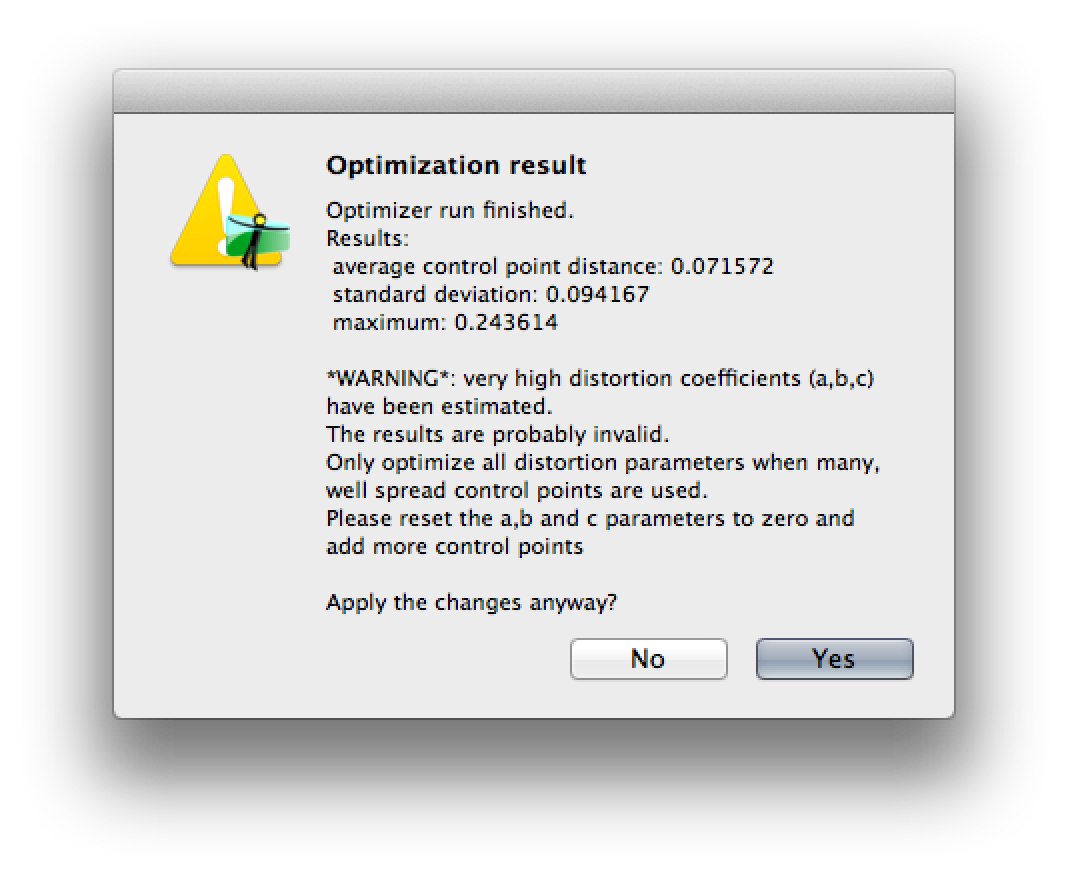
- When I optimize I often get a warning (see screenshot) with the “optimized” parameters set to very large (and very extreme) values such as: a = 315.2, b = 2061.9, c = 13,759.1.
- If I enable the edit script before optimizing checkbox then I can see that the values in the GUI don’t get copied properly into the script. For example, the GUI will show a = b = c = 0, but the values in the scrip will be a1e-05 b1e-05 c1e-05.
- If I manually correct those values in the script then the optimizer will do nothing and set a = b = c = 0.
Here’s the full text of the script that Hugin is creating. Does anyone see what’s wrong or know how to fix it?
Thanks!
# PTOptimizer script, written by hugin


p f0 w3000 h2028 v50  n"TIFF_m c:LZW r:CROP"
m g1 i0 f0 m2 p0.00784314


# image lines
#-hugin  cropFactor=2.72727
i w5496 h3672 f0 v50 r0 p0 y0 TrX0 TrY0 TrZ0 a0 b0 c0 d0 e0 g0 t0  n"/Lens Charts/DSC09994.tiff"


# specify variables that should be optimized
v a0
v b0
v c0
v


# control points
c n0 N0 x72 y287 X72 Y286 t3
c n0 N0 x1502 y195 X1501.99870237282 Y194.99938673054 t3
c n0 N0 x2781 y162 X2781.00029095988 Y161.998663015188 t3
c n0 N0 x4051 y206 X4050.99823271141 Y206.000735219853 t3
c n0 N0 x5464 y305 X5463.99811267938 Y305.001046487068 t3
c n0 N0 x106 y3360 X106 Y3360 t4
c n0 N0 x1518 y3452 X1518.00019921348 Y3452.01545669996 t4
c n0 N0 x2772 y3486 X2771.99878319084 Y3486.01808107785 t4
c n0 N0 x4027 y3452 X4026.99979692598 Y3452.01619932263 t4
c n0 N0 x5432 y3359 X5432.00103397834 Y3358.99965878955 t4


#hugin_optimizeReferenceImage 0
#hugin_blender enblend
#hugin_remapper nona
#hugin_enblendOptions
#hugin_enfuseOptions
#hugin_hdrmergeOptions -m avg -c
#hugin_outputLDRBlended true
#hugin_outputLDRLayers false
#hugin_outputLDRExposureRemapped false
#hugin_outputLDRExposureLayers false
#hugin_outputLDRExposureBlended false
#hugin_outputLDRStacks false
#hugin_outputLDRExposureLayersFused false
#hugin_outputHDRBlended false
#hugin_outputHDRLayers false
#hugin_outputHDRStacks false
#hugin_outputLayersCompression LZW
#hugin_outputImageType tif
#hugin_outputImageTypeCompression LZW
#hugin_outputJPEGQuality 90
#hugin_outputImageTypeHDR exr
#hugin_outputImageTypeHDRCompression LZW
#hugin_outputStacksMinOverlap 0.7
#hugin_outputLayersExposureDiff 0.5
#hugin_optimizerMasterSwitch 0
#hugin_optimizerPhotoMasterSwitch 0

Terry Duell
Aug 28, 2014, 5:55:56 AM8/28/14
to hugi...@googlegroups.com
On Thu, 28 Aug 2014 19:02:54 +1000, Dave Thorup <kuwa...@gmail.com> wrote:
>
> Does anyone have any suggestions?
>
I had a quick look a manual calibration using your image, pretty much as
>
> Does anyone have any suggestions?
>
per the tutorial, and obtained the values of a=0.13, b=-0.451, c=0.364.
I think one could do better using a few more lines, but it might help as
an example.
The .pto for this project is attached.
Hope that helps.
Cheers,
--
Regards,
Terry Duell
Dave Thorup
Aug 28, 2014, 2:17:10 PM8/28/14
to hugi...@googlegroups.com
Aha thanks! I figured out my problem. I didn’t realize that the Control Points should be placed on opposite ends of the line that’s being defined. So for example, if I’m defining a horizontal line I should define a point on the left side of the left image and then match that point on the right side of the right image and work my way towards the center. I had thought that I just needed define a point in the left image and then match the point to the same place in the right image.
It wasn’t obvious from the tutorials that I was following that you’re supposed to define the control points like that.
Thanks again!
Cheers,
Dave
Terry Duell
Aug 28, 2014, 8:20:11 PM8/28/14
to hugi...@googlegroups.com
On Fri, 29 Aug 2014 04:17:10 +1000, Dave Thorup <kuwa...@gmail.com> wrote:
> Aha thanks! I figured out my problem. I didn’t realize that the Control
> Points should be placed on opposite ends of the line that’s being
> defined.
> So for example, if I’m defining a horizontal line I should define a point
> on the left side of the left image and then match that point on the right
> side of the right image and work my way towards the center. I had thought
> that I just needed define a point in the left image and then match the
> point to the same place in the right image.
>
> It wasn’t obvious from the tutorials that I was following that you’re
> supposed to define the control points like that.
>
Well that's the way I have been doing it. I haven't experimented with
> Aha thanks! I figured out my problem. I didn’t realize that the Control
> Points should be placed on opposite ends of the line that’s being
> defined.
> So for example, if I’m defining a horizontal line I should define a point
> on the left side of the left image and then match that point on the right
> side of the right image and work my way towards the center. I had thought
> that I just needed define a point in the left image and then match the
> point to the same place in the right image.
>
> It wasn’t obvious from the tutorials that I was following that you’re
> supposed to define the control points like that.
>
other ways of placing the points.
Images like the attached, of buildings with clear straight lines, are
handled quite well by Hugin Calibrate Lens, which does make it a much
simpler process.
Dave Thorup
Sep 3, 2014, 2:59:12 PM9/3/14
to hugi...@googlegroups.com
I would much rather use the Calibrate Lens app, except that it doesn’t detect intersecting lines. Which makes it mostly useless for the existing images that I have (which is a lot). Does anyone know why the Calibrate Lens app doesn’t support intersecting lines? And how hard would it be to add that support?
Reply all
Reply to author
Forward
0 new messages