Mosiac model - convergence, accuracy?

paul womack
I have recently completed shooting a very careful trial, using
a cantilevered tripod (Benbo) over a map on my dining table.
(I shot at less than maximum resolution, at 3 Mp to cut down
the data size)
All the shots (30 in all) are accurately focused and sharp.
I found that for this large image set, it is neccessary
to perform step-wise addition and optimisation
of the images (initially just X and Y).
Simple hoping that the optimiser will just "sort it all out"
doesn't work, at least with the kind of control point
set found by automation. it works OK with "nigh-perfect"
control point sets (I just found ;-)
In practise I found that
as I proceeded, I needed to hand edit a "fairly good"
position of X and Y to get the optimisation to converge at all.
This is doable (since my images form a simple matrix)
but more work than I'd like.
(I also regret that the ctrl-T short cut for "optimise"
is not available on the preview window)
My more significant concern is that my "final" optimisation,
has a disappointingly large error, and (indeed)
shows stitching glitches on final output.
Since my map is nigh 2 dimensional, and I went to considerable
pains to shoot a narrow FOV from a good distance above the
map, I believe that the mosaic model should be able to get
VERY close to perfect on this image set, and yet it doesn't.
I am aware that I may be one of the more extreme users
of the mosaic model; is it believed to be bug free?
I would be able to test this by synthesizing scaled and YPR skewed
sub-images from a high res original (e.g. a giga-pan) and then attempting
to stitch them using mosaic mode.
I would rather not go to this effort unless forced.
I have uploaded the images and project file at
https://www.hightail.com/download/bXBhZEV5VnNreEJEZU1UQw
They will be there for a week. Note that I believe the
map test subject to be in copyright.
BugBear
bugbear
(more experiments below)
>
> My more significant concern is that my "final" optimisation,
> has a disappointingly large error, and (indeed)
> shows stitching glitches on final output.
>
> Since my map is nigh 2 dimensional, and I went to considerable
> pains to shoot a narrow FOV from a good distance above the
> map, I believe that the mosaic model should be able to get
> VERY close to perfect on this image set, and yet it doesn't.
avg: 2.28
std: 1.80
max: 16.2
Suspecting that my map might be poorly printed, I removed
all the horiz and vert control points, and just left the anchor
with a fixed roll, to keep the pano "right way up".
avg: 2.21
std: 2.18
max: 43.8
Which, despite being less constrained (more optimised) gives a worse result?!
But If I now allow the anchor roll to be optimised (rotating the whole panorama, of course) I
get the rather better:
avg: 0.79
std: 0.57
max: 4.00
and it has swung the whole pano around 180 degrees.
If anyone can explain what's going on, I'd be grateful.
BugBear

Terry Duell
On Tue, 26 May 2015 21:36:00 +1000, paul womack <pwo...@papermule.co.uk>
wrote:
> The convergence behaviour of the mosaic model is really quite poor.
>
> I have uploaded the images and project file at
>
on walls, but your case might have exposed a problem.
I'll have a look at your project.
Cheers,
--
Regards,
Terry Duell
Terry Duell
On Wed, 27 May 2015 08:40:18 +1000, Terry Duell <tdu...@iinet.net.au>
wrote:
> I'll have a look at your project.
I did a little editing of control points, and removed the vertical and
horizontal CPs, and the optimisation now looks pretty good. I did have to
correct roll using 'move/drag' in the fast preview window. My project file
is attached.
Automatically finding good CPs on maps can be a bit problematic. For some
projects it can end up being less work manually adding the CPs.
I did use the new 'EditCP' tool in hugin-2015.0.0, which made finding and
removing the worst of the CPs an easy task.
This result would suggest to me that the mosaic mode is working OK.
Terry Duell
wrote:
[snip]
> I did have to correct roll using 'move/drag' in the fast preview window.
fix it.
Mean error 0.5, max 2.9.
bugbear
> Hello Paul,
>
> On Wed, 27 May 2015 08:40:18 +1000, Terry Duell <tdu...@iinet.net.au> wrote:
>
>
>> I'll have a look at your project.
>
> I think it all boils down to 'good' and 'less good' control points.
> I did a little editing of control points, and removed the vertical and horizontal CPs, and the optimisation now looks pretty good. I did have to correct roll using 'move/drag' in the fast preview window. My project file is attached.
> Automatically finding good CPs on maps can be a bit problematic. For some projects it can end up being less work manually adding the CPs.
> I did use the new 'EditCP' tool in hugin-2015.0.0, which made finding and removing the worst of the CPs an easy task.
see how you got benefit from the tool.
You clearly know something I don't.
Teach me, oh master!
(in general I suspect people don't use the CP editor much; on my laptop,
with a 1366x768 display, the image windows are only 669x381 pixels
in full screen mode.
(and see my other request for a "don't show the contrast enhanced square in this window") option.
> This result would suggest to me that the mosaic mode is working OK.
>
> Cheers,
>
>
> Mean error 0.5, max 2.9.
The result is also surprisingly square, given the lack of all but 1 vertical and horizontal CPs.
Well, except it's upside down...
For purely cosmetic reasons, I gave it a 180 degree rotate (in move/drag),
and centred it (in move/drag via X/Y edit)
Anyway - I tried to center the pano, using mosaic move/drag to alter the X Y.
I just though I'd do an optimise, just to be sure this "finished" pano was stable.
And after 213 iterations, it converged again, upside down, pretty much back where it started.
There is "some kind" of optimisation attractor which I don't understand, such
that X Y are interacting with Y P R.
I had thought (till now) that X Y Z only really had meaning realtive
to each other (so that the position of the anchor was entirely arbitrary),
but given the existence of such an attractor, it seemed there must
be a "best position" for the anchor (which implies that X Y coordinates
are not just relative to each other), so I added X and Y for the anchor
to the optimisation variables and let the optimiser loose.
It converged:
avg: 0.008403
std: 0006875
max: 0.0617
with (anchor) X=-85, Y=0.7
which sounds suspiciously similar to the sort of optimisation
that results in a tiny FOV (massive focal length). It just puts all the images
in a tiny dot.
It looks like the mosaic model makes the mapped images smaller (and hence CP pixel
distances smaller) as X and Y are further from the origin. I believe this is the driver of
the bogus attractor I'm seeing.
BugBear
Roger Broadie
I thought your panorama was pretty good, but I don’t think you have
fully overcome the problems of parallax resulting from creases and
folds. The main cause, I suspect, is the camera tilt of 6 deg plus or
minus from the vertical that the pitch values of the optimiser imply.
So while I would not normally expect to include the Plane Yaw and Pitch
parameters in a truly planar photomosaic, it did seem worth trying them
here. They do seem to help.
I attach panoa.pto, based on your file, which takes that approach and
also includes some tuning of the control points and fuller lens
optimisation. But I hung on to the h and v points, because I think they
are one of Hugin’s strengths. I have resolved some remaining glitches,
either with added control points – automatic control point finders seem
to find otherwise featureless areas of grid-lines difficult to deal with
– or with masking, but have not tried fully to resolve problems with the
grid-square P25, where the different shapes of the square as captured in
e.g. images 17 and 23 illustrate graphically the problems of the
parallax present in places in your images. The end result yields an
average error of 1.2 pixels and a maximum of 3.2, for a panorama
matching that of pano.pto in size.
Broadly, I agree with Terry Duell (Wed, 27 May 2015 at 10:13:42 +1000)
that the mosaic mode is working OK. He has given us a pto file (Wed, 27
May 2015 at 12:34:56 +1000) that does not use the Plane Yaw and Pitch
parameters. It has an error of 0.5 average and 2.9 maximum, but is for
a panorama of only about half the width of yours. Still pretty good,
though, even at the full size.
Roger Broadie
Terry Duell
On Wed, 27 May 2015 19:45:54 +1000, bugbear <bug...@papermule.co.uk>
wrote:
[snip]
>> I did use the new 'EditCP' tool in hugin-2015.0.0, which made finding
>> and removing the worst of the CPs an easy task.
>
> How did you do this? Each image on the preview is tiny (since I have 30
> images), so I don't
> see how you got benefit from the tool.
>
much as I can while still keeping the bad points in view.
[snip]
>>
>> Adding just one vertical line, in the one image, is all that is needed
>> to fix it.
>> Mean error 0.5, max 2.9.
>
> Perfect!
>
> The result is also surprisingly square, given the lack of all but 1
> vertical and horizontal CPs.
>
> Well, except it's upside down...
>
were shot in that orientation. The simplest solution would be to stitch
and then do a 180 rotation in an image viewer.
bugbear
> Hello Paul,
>
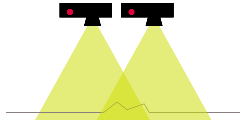
> I thought your panorama was pretty good, but I don’t think you have fully overcome the problems of parallax resulting from creases and folds. The main cause, I suspect, is the camera tilt of 6 deg plus or minus from the vertical that the pitch values of the optimiser imply.
vertical w.r.t item directly beneath it, it is (of course) at an angle to items at the edge of its FOV. When the camera
is translated in X,Y, (possibly Z), the item is now at a different point in the new FOV.
Diagram attached.
>
> So while I would not normally expect to include the Plane Yaw and Pitch parameters in a truly planar photomosaic, it did seem worth trying them here. They do seem to help.
the sub-plane parameters may help, at least "on average".
> I attach panoa.pto, based on your file, which takes that approach and also includes some tuning of the control points and fuller lens optimisation. But I hung on to the h and v points, because I think they are one of Hugin’s strengths. I have resolved some remaining glitches, either with added control points – automatic control point finders seem to find otherwise featureless areas of grid-lines difficult to deal with – or with masking, but have not tried fully to resolve problems with the
> grid-square P25, where the different shapes of the square as captured in e.g. images 17 and 23 illustrate graphically the problems of the parallax present in places in your images. The end result yields an average error of 1.2 pixels and a maximum of 3.2, for a panorama matching that of pano.pto in size.
>
> Broadly, I agree with Terry Duell (Wed, 27 May 2015 at 10:13:42 +1000) that the mosaic mode is working OK. He has given us a pto file (Wed, 27 May 2015 at 12:34:56 +1000) that does not use the Plane Yaw and Pitch parameters. It has an error of 0.5 average and 2.9 maximum, but is for a panorama of only about half the width of yours. Still pretty good, though, even at the full size.
My problem of how to best capture a 1816 map remains, of course. :-)
BugBear
bugbear
> grid-square P25, where the different shapes of the square as captured in e.g. images 17 and 23 illustrate graphically the problems of the parallax present in places in your images.
(see attached)
BugBear
Roger Broadie
an isolated area of crumpling (and yes, I know it's only a diagram, but
the situation does arise in reality), to take an extra photo from
directly above the crumpled area and looking straight down on it and
then force the use of that version with an Include mask. It's probably
better to avoid control points in the actual crumpled area because of
the parallax they embody.
The situation is thus analogous to taking a photomosaic of a church
elevation, where, for instance, it's vital to take images of protruding
features like buttresses and receding features like windows from
straight-on and then select those versions with masking. I think there
was an early tutorial on the topic.
Roger Broadie

Don Johnston
http://m.instructables.com/id/Bargain-Price-Book-Scanner-From-A-Cardboard-Box/
> --
> A list of frequently asked questions is available at: http://wiki.panotools.org/Hugin_FAQ
> ---
> You received this message because you are subscribed to the Google Groups "hugin and other free panoramic software" group.
> To unsubscribe from this group and stop receiving emails from it, send an email to hugin-ptx+...@googlegroups.com.
> To view this discussion on the web visit https://groups.google.com/d/msgid/hugin-ptx/5566CCBF.2070501%40papermule.co.uk.
> For more options, visit https://groups.google.com/d/optout.
bugbear
> Have you thought of using a piece of glass over the section you are photographing to get rid of the 3rd dimension (flatten the folds). Then you have to light it from an angle to ensure there is no glare. Take a look at this article on building a cheap book scanner. They aren't using any special type of glass.
BugBear
Don Johnston
> --
> A list of frequently asked questions is available at: http://wiki.panotools.org/Hugin_FAQ
> ---
> You received this message because you are subscribed to the Google Groups "hugin and other free panoramic software" group.
> To unsubscribe from this group and stop receiving emails from it, send an email to hugin-ptx+...@googlegroups.com.
> To view this discussion on the web visit https://groups.google.com/d/msgid/hugin-ptx/55673A3F.6090200%40papermule.co.uk.

Carl von Einem
> you are photographing to get rid of the 3rd dimension (flatten
> the folds). Then you have to light it from an angle to ensure
> there is no glare. Take a look at this article on building a
> cheap book scanner. They aren't using any special type of
> glass.
> http://m.instructables.com/id/Bargain-Price-Book-Scanner-From-A-Cardboard-Box/
object so ideally no reflections can find their way into the lens. Also
shade the reflector(s) so no direct light hits the lens. So if you see
the light when looking through the viewfinder something is wrong.
bugbear
> Isn't the answer to the situation shown in your diagram, where there is an isolated area of crumpling (and yes, I know it's only a diagram, but the situation does arise in reality), to take an extra photo from directly above the crumpled area and looking straight down on it and then force the use of that version with an Include mask. It's probably better to avoid control points in the actual crumpled area because of the parallax they embody.
>
> The situation is thus analogous to taking a photomosaic of a church elevation, where, for instance, it's vital to take images of protruding features like buttresses and receding features like windows from straight-on and then select those versions with masking. I think there was an early tutorial on the topic.
Since the mosaic features only work on a 2D plane, any 3D features
need special handling.
I note from this tutorial:
https://panospace.wordpress.com/2010/09/19/linear-panoramas-mosaic-tutorial/
that:
"It is paramount that all CPs are on the same plane
and no currently existing CP detector known to me
meets the condition. Even small depth
errors (e.g. relief on a wall) has big impact."
I will go back and revue Terry Duell's super-successful stitch;
(email of 27/05/15 03:34; avg: 0.48, std: 0.332, max 1.98).
Terry says he (mainly) achieved this by removing bad control points;
I suspect that CPs on 3D items might well fulfil a numeric definition
of "bad".
BugBear