VLF Antenna Site Isolation

Jonathan
As was seen in the SAQ spectrum plot, there were prominent mains harmonics in that section of spectrum. Normally that isn't the case, as mains harmonics typically tail off at around 6-8 kHz. I was showing my spectrum plot to Paul, the author of vlfrx-tools and a VLF enthusiast for over 20 years with many advancements for VLF reception at home to the VLF community. His website is abelian.org and runs and publishes data from a network of VLF receivers for both natural radio events and VLF amateur transmissions in the Dreamer’s band.

Julius Madey
The only problem with the solar power/battery bank concept for the remote site is low temperature charging characteristics of most of the battery chemistries. Both Lithium ion and LiFePO4 batteries can be damaged by charging at temperatures below 0 C. Nickel Cadmium batteries are probably the best choice for an all weather relatively low power solar recharge system for the remote use we're considering.
Jules-K2KGJ
Hi Jules,

The TI part is the ISOW7741 and the product page is at:
https://www.ti.com/product/ISOW7741

The built in isolated DC-DC converter can source 140mA at 3V from a 5V
source. For the Raspberry Pi side, it can source 110mA at 5V from a 5V
source. This may or may not be enough to drive the long cable length
loop, but there are other options, like using a separate isolated
DC-DC converter on the Pi side.

This application note shows circuit examples for only isolating I2C
and isolating both power and I2C. In the case of the I2C differential
driver, it would be placed in the loop between the Pi and magnetometer
on both ends. You can read it here:
https://www.ti.com/lit/an/slla417b/slla417b.pdf

I don't believe ferrites would be all that effective because mains
harmonics are within the spectrum of interest, so that spectrum would
also be attenuated by the ferrite on the line. Plus, the contamination
is at the VLF receiver through the frontend and I think ferrites could
negatively affect the circuit. Ferrites may work on the magnetometer
cable, for example, if the shield or wires may be delivering the mains
harmonics.

Fiber and battery power is an excellent idea. I had planned on using
such an arrangement on my VLF receiver and still plan to. I would like
to see if removing the ground wire improves the noise floor and the
magnetometer cable may not affect it that much, but I do believe there
is benefit to isolating both power and data.

Yes, it would be pretty easy to remove as the ground is still soft.
Hopefully we can return the wire to the electrical supply store.

Thanks Jules!

Jonathan
KC3EEY

On 1/3/22, Julius Madey <hil...@fairpoint.net> wrote:
Jonathan, Good discussion ... What is the part number of the TI device you mentioned? I am currently working on integrating another type of magnetometer which needs a source of well regulated and low noise 5 volts and, which also may require as much as 5 watts of power remotely to power a temperature controlled enclosure for the magnetometer at surface, not subsurface, level. As opposed to a full galvanic isolation scheme, it should also be possible to use ferrites effective isolation at some nominal low cutoff frequency. You might try asking Paul about his experience with lossy ferrite isolation. Of course, the cleanest solution is probably to provide local power (solar panel / battery) at the remote site with optical fiber for communications ... eliminating any possibility that RF data links could inadvertently interfere with the VLF / Grape receiver systems. Bit of a loss in time and money, but you could pull the cable out of Nathaniel's conduit run and replace it with optical fiber .... no need to make another dig. On the same note, if the presence of the ground wire, even if disconnected at both ends, is still a problem, I think it could be extracted by a straight pull in line with the conduit (winch on an RV or pickup????). Jules On 1/3/2022 11:20 AM, Jonathan wrote:
Hi All,

As was seen in the SAQ spectrum plot, there were prominent mains
harmonics in that section of spectrum. Normally that isn't the case,
as mains harmonics typically tail off at around 6-8 kHz. I was showing
my spectrum plot to Paul, the author of vlfrx-tools and a VLF
enthusiast for over 20 years with many advancements for VLF reception
at home to the VLF community. His website is abelian.org
<http://abelian.org> and runs and publishes data from a network of VLF
receivers for both natural radio events and VLF amateur transmissions
in the Dreamer’s band.

Paul and I had a long discussion about these harmonics and the VLF
system site installation. He asked the initial question:

/Impressed that you're getting mains harmonics so high, have you got
something clipping somewhere?/
/
/
Because I was using his VLF preamp design and he added a lot of
headroom for strong mains hum and sferics in the front end, there
definitely wasn’t any clipping. The audio level was quite reasonable
and even the strongest sferics would be no greater than 45% of the
soundcard’s input range. Initially, he wanted me to perform an
experiment by wrapping grounded foil on the antenna, but after looking
at some captures of the VLF spectrum, he decided it wasn’t necessary
to perform the experiment. The experiment was to attempted to
eliminate a potential source of harmonics, any clipping in the VLF
preamp /feedline chain. Paul then talked about the issues that heavy
mains harmonics can cause for a VLF receiver:

/You'll find that with a mains harmonic spectrum like this, your
system noise floor is also significantly raised. The mains
cross-modulates with the VLF noise to raise the floor, and you can
hear that, as a sizzling frying sound to the noise rather than a pure
hiss./

This was exactly what was going on. It can be heard very clearly in
the mains filtered stream and the raised noise floor, with mains
harmonics extending beyond 20 kHz, can be seen in the spectrum
display. The problem is, the increased noise floor makes weak signals
from natural radio events and amateurs difficult to detect. This was
clearly seen in the SAQ spectrum plot, as the mains harmonics were
much more stronger than the weak SAQ transmission. I described the
site installation and showed him pictures that included the installed
active VLF antenna, conduit with ground wire, and ground magnetometer.
Paul then went on:

/Looks like a fine installation in an enviable location and just about
far enough from the trees, the VLF reception looks good./
/You have three good reference signals coming in: NAA, NAU, NML./
/No sign at all of any clipping and the incoming 60Hz and harmonics
are nowhere near strong enough to overload the pre-amp or SP70./
/Wrapping the antenna doesn't just hinder the E-field pick-up, it also
shunts the ground pick-up too: The pre-amp amplifies the potential
difference between local ground and E-field and the wrap just puts a
capacitive shunt across its input, thus reducing the response to both
'sources', a non-invasive way to temporarily drop the pre-amp input
level. But it seems you're not overloading so no need to do this test./

Paul makes a good point here which I wanted to emphasize that the
earth ground connection is part of the antenna, so shunting the
antenna element would also shut any pickup from the earth ground
connection, as the potential difference between the antenna element
and earth ground is what the input of the front end is seeing. Paul,
continuing, comments about the source of the heavy mains harmonics:

/We are probably seeing noise on the domestic ground getting into the
rx ground circuit somehow. The spectrum and waveform looks very
typical of switching PSU interference, UPS, chargers, etc, typical
domestic ground noise./
/I see a ground wire dropping down from the pre-amp into earth, that
should be the only ground connection out at the site. The cat6 screen
and the extra conductor in the conduit are both potential sources of
trouble, providing channels to bypass the isolation and couple the
domestic ground and the noise it carries, out to the receiver site
ground./
/Where/what does the conduit ground wire connect to at each end?/
/I see two conduits, a grey with box which is presumably the cat6
downlink/power, and a white with a single cable, is that the head of a
ground stake/?

Here, Paul reflected my initial fears with adding any grounds and low
impedance paths between the antenna site and residence. On the VLF
preamp, both power and audio lines are magnetically isolated as well
as at the residence inside the Raspberry Pi box. This isolation is
critical to keeping mains hum and harmonics out of the VLF spectrum. I
mentioned the magnetometer’s cable shield was isolated, enclosed in
the “white conduit” he mentions. I told him the shield on the cat6 VLF
receiver feedline is also floating. I also mentioned the ground wire
is just coiled up and laying on the ground at both ends. Paul goes on:

/The likely culprit is that ground wire, outside the conduit, it will
be galvanically grounded all the way along./
/By connecting the two earth zones you're bringing all the muck on the
domestic ground out to the rx site, bypassing all your DC and signal
isolation efforts, you may as well move all the antennas back to the
residence./

I seconded his sentiments. The ground wire is the lowest impedance
path. I do believe there is a high likelihood of these harmonics are
primarily coming from this ground wire, seeing as the site is fairly
remote with low hum levels and domestic interference, but even so,
without some isolation from domestic sources, even the quietest of
radio-quiet areas can furnish interference in the form of ground
currents. Finally, Paul proposes an excellent solution, not only for
this case, but for future PSWS users who want to co-site a VLF
receiver with the magnetometer and HF antennas:

/That ground wire might also be a good way to channel lightning
currents back to the residence, at least for the few microseconds
before the thin wire vapourises. A better solution would be a good
solid earthing arrangement at the rx site, establishing a firm and
clean local ground for all the electronics and a short low inductance
sink for lightning currents. This, combined with isolation on all DC
and signal circuits in the conduit, and suitable surge protection at
key points, ought to protect the residence./
/You're going to co-site things like HF loops and magnetometer and
their power/signal links would need to be isolated too, to both offer
an un-inviting path to lightning currents and to keep at bay the
residence ground noise. The I2C link could be a challenge there. At
some point it gets easier to digitise at the remote site and have a
single isolated power and data link./

I feel Paul’s argument here is a good one, and can be used for the
benefit of the PSWS. Good, solid grounding at the local antenna site
with isolation on all feedline a will not only keep domestic mains
harmonics from polluting the antenna site ground, but offer good
lightning protection for the residence. This also brings up a case for
both power and signal isolation of the magnetometer, on both ends,
that could add a lot of benefit for the magnetometer’s performance. It
has been shown by Bill that the Pi host does create some interference
in the HF bands, and isolation would be a great mitigation measure. TI
makes an IC with both I2C and power isolation that could work quite
well in a future revision.

Jonathan
KC3EEY


/
/


--
Please follow the HamSCI Community Participation Guidelines at
http://hamsci.org/hamsci-community-participation-guidelines.
---
You received this message because you are subscribed to the Google
Groups "HamSCI" group.
To unsubscribe from this group and stop receiving emails from it, send
an email to hamsci+un...@googlegroups.com.
To view this discussion on the web visit
https://groups.google.com/d/msgid/hamsci/CAOY0kB2DhF0qAsen3dcb3Ug_Cu9ONjCo4GYAHouUXzmHkbkc9Q%40mail.gmail.com

<https://groups.google.com/d/msgid/hamsci/CAOY0kB2DhF0qAsen3dcb3Ug_Cu9ONjCo4GYAHouUXzmHkbkc9Q%40mail.gmail.com?utm_medium=email&utm_source=footer>.

Gerald Creager
Capt Gerry Creager, CAP
SWR Health Services Officer(C) 979.229.5301
Civil Air Patrol, U.S. Air Force Auxiliary
gocivilairpatrol.com
To view this discussion on the web visit https://groups.google.com/d/msgid/hamsci/f35b301a-2e89-4fc8-a7c5-938a8902c8dd%40fairpoint.net.
Julius Madey
Jules-K2KGJ
To view this discussion on the web visit https://groups.google.com/d/msgid/hamsci/CAG3zga6oOofphV_-4SeFBjXv1Y4xw1mFrgm%2BiJuMCOaa47eCYA%40mail.gmail.com.

Lanzerotti, Louis J.
To view this discussion on the web visit https://groups.google.com/d/msgid/hamsci/b40e5460-0340-7a3c-bd94-9b06de285112%40fairpoint.net.

MNaruta GMail
My apologies Nathaniel and Jonathan, for my bad advice on
burying a ground wire near the conduit.
In my broadcast and LMR experience, we wanted to bond everything
together.
Michael Naruta - AA8K
On 1/3/22 11:20 AM, Jonathan wrote:
> Hi All,
>
> As was seen in the SAQ spectrum plot, there were prominent mains
> harmonics in that section of spectrum. Normally that isn't the
> case, as mains harmonics typically tail off at around 6-8 kHz. I
> was showing my spectrum plot to Paul, the author of vlfrx-tools
> and a VLF enthusiast for over 20 years with many advancements
> for VLF reception at home to the VLF community. His website is
> and VLF amateur transmissions in the Dreamer’s band.
>
> Paul and I had a long discussion about these harmonics and the
> VLF system site installation. He asked the initial question:
>
> got something clipping somewhere?/
> /
> /
> headroom for strong mains hum and sferics in the front end,
> there definitely wasn’t any clipping. The audio level was quite
> reasonable and even the strongest sferics would be no greater
> than 45% of the soundcard’s input range. Initially, he wanted me
> to perform an experiment by wrapping grounded foil on the
> antenna, but after looking at some captures of the VLF spectrum,
> he decided it wasn’t necessary to perform the experiment. The
> experiment was to attempted to eliminate a potential source of
> harmonics, any clipping in the VLF preamp /feedline chain. Paul
> then talked about the issues that heavy mains harmonics can
> cause for a VLF receiver:
>
> cross-modulates with the VLF noise to raise the floor, and you
> can hear that, as a sizzling frying sound to the noise rather
> This was exactly what was going on. It can be heard very clearly
> in the mains filtered stream and the raised noise floor, with
> mains harmonics extending beyond 20 kHz, can be seen in the
> spectrum display. The problem is, the increased noise floor
> makes weak signals from natural radio events and amateurs
> difficult to detect. This was clearly seen in the SAQ spectrum
> plot, as the mains harmonics were much more stronger than the
> weak SAQ transmission. I described the site installation and
> showed him pictures that included the installed active VLF
> antenna, conduit with ground wire, and ground magnetometer. Paul
> then went on:
>
> about far enough from the trees, the VLF reception looks good./
> /You have three good reference signals coming in: NAA, NAU, NML./
> /No sign at all of any clipping and the incoming 60Hz and
> /Wrapping the antenna doesn't just hinder the E-field pick-up,
> potential difference between local ground and E-field and the
> wrap just puts a capacitive shunt across its input, thus
> reducing the response to both 'sources', a non-invasive way to
> temporarily drop the pre-amp input level. But it seems you're
> Paul makes a good point here which I wanted to emphasize that
> the earth ground connection is part of the antenna, so shunting
> the antenna element would also shut any pickup from the earth
> ground connection, as the potential difference between the
> antenna element and earth ground is what the input of the front
> end is seeing. Paul, continuing, comments about the source of
> the heavy mains harmonics:
>
> looks very typical of switching PSU interference, UPS, chargers,
> /I see a ground wire dropping down from the pre-amp into earth,
> cat6 screen and the extra conductor in the conduit are both
> potential sources of trouble, providing channels to bypass the
> isolation and couple the domestic ground and the noise it
> /Where/what does the conduit ground wire connect to at each end?/
> /I see two conduits, a grey with box which is presumably the
> Here, Paul reflected my initial fears with adding any grounds
> and low impedance paths between the antenna site and residence.
> On the VLF preamp, both power and audio lines are magnetically
> isolated as well as at the residence inside the Raspberry Pi
> box. This isolation is critical to keeping mains hum and
> harmonics out of the VLF spectrum. I mentioned the
> magnetometer’s cable shield was isolated, enclosed in the “white
> conduit” he mentions. I told him the shield on the cat6 VLF
> receiver feedline is also floating. I also mentioned the ground
> wire is just coiled up and laying on the ground at both ends.
> Paul goes on:
>
> will be galvanically grounded all the way along./
> /By connecting the two earth zones you're bringing all the muck
> and signal isolation efforts, you may as well move all the
> I seconded his sentiments. The ground wire is the lowest
> impedance path. I do believe there is a high likelihood of these
> harmonics are primarily coming from this ground wire, seeing as
> the site is fairly remote with low hum levels and domestic
> interference, but even so, without some isolation from domestic
> sources, even the quietest of radio-quiet areas can furnish
> interference in the form of ground currents. Finally, Paul
> proposes an excellent solution, not only for this case, but for
> future PSWS users who want to co-site a VLF receiver with the
> magnetometer and HF antennas:
>
> microseconds before the thin wire vapourises. A better solution
> would be a good solid earthing arrangement at the rx site,
> establishing a firm and clean local ground for all the
> electronics and a short low inductance sink for lightning
> currents. This, combined with isolation on all DC and signal
> circuits in the conduit, and suitable surge protection at key
> /You're going to co-site things like HF loops and magnetometer
> both offer an un-inviting path to lightning currents and to keep
> at bay the residence ground noise. The I2C link could be a
> challenge there. At some point it gets easier to digitise at the
Jonathan
I think that both ICs (with and without power) would work pretty well.
I know the magnetometer works perfectly fine without isolation, but I
do believe that it adds a lot of benefit in general, including any
situation where unwanted signals can be fed back, like what Bill
experienced, and for VLF receivers. It would be a good addition to a
new layout revision, and may help a lot of people in the future
because everyone has different installations/local conditions.
I had planned on using a small SLA battery at the site with high
current capability for VLF receivers. It'll power the receiver for a
few months before it'll need to be charged, and you can have one
inside, trickle charging and ready to change. Plus, it gives you a
good excuse to go out and work on the antenna. Do you find the need to
clean the solar panels often? A benefit to an outdoor charging
arrangement would be continuous power with no interruptions, but the
same can be achieved with parallel battery connections. For the lower
voltage magnetometer, a DC-DC would be required if you use a SLA.
Michael,
No worries! Your advice was not bad at all. In fact, it was excellent
advice because it is an effective way of channeling lightning currents
away from an antenna site. We still don't know exactly is channeling
these mains harmonics and it could be from other sources as well. The
ground wire is likely, but some more troubleshooting is required.
Thank you for your advice that you've given me on many different
topics! I appreciate it all and learned so much from you.
And the same is true for you Jules! Thank you so much for all of your
advice and all that I've learned from you!
Jonathan
KC3EEY
> Please follow the HamSCI Community Participation Guidelines at
> http://hamsci.org/hamsci-community-participation-guidelines.
> ---
> You received this message because you are subscribed to the Google Groups
> "HamSCI" group.
> To unsubscribe from this group and stop receiving emails from it, send an
> email to hamsci+un...@googlegroups.com.
> To view this discussion on the web visit
>

Dr. Nathaniel A. Frissell Ph.D.
Like Jonathan said, no worries at all! Thank you for all of the suggestions. This is part of the process.
73 Nathaniel W2NAF
> On Jan 4, 2022, at 9:10 PM, MNaruta GMail <mna...@gmail.com> wrote:
>
>
> My apologies Nathaniel and Jonathan, for my bad advice on burying a ground wire near the conduit.
>
> In my broadcast and LMR experience, we wanted to bond everything together.
>
>
> Michael Naruta - AA8K
>
>
>
> On 1/3/22 11:20 AM, Jonathan wrote:
>> Hi All,
> Please follow the HamSCI Community Participation Guidelines at https://nam10.safelinks.protection.outlook.com/?url=http%3A%2F%2Fhamsci.org%2Fhamsci-community-participation-guidelines&data=04%7C01%7Cnathaniel.frissell%40scranton.edu%7C25f541ffb7594d1fd0f208d9cff0a522%7Ca8edc49a41f14c699768a7f6d7c3b8c3%7C0%7C0%7C637769455817903205%7CUnknown%7CTWFpbGZsb3d8eyJWIjoiMC4wLjAwMDAiLCJQIjoiV2luMzIiLCJBTiI6Ik1haWwiLCJXVCI6Mn0%3D%7C3000&sdata=w%2Fcuoj7BskrhNSxZJpCj%2Foyg2hBBNy0XvGi7Ge4g7to%3D&reserved=0.
> To unsubscribe from this group and stop receiving emails from it, send an email to hamsci+un...@googlegroups.com.
Jonathan


I'm measuring almost exactly 20dB reduction of the noise floor,
much more like a properly isolated VLF receiver should be.
Still a little bit of scratchy interference from somewhere
which I haven't identified yet. It was there before but
weaker now I think.
I've added vlf44 to the fbins page and the extra isolation
makes a big difference,
http://5.9.106.210/fbins3.html#r=vlf44&f=8270&p=1650895200&b=000&s=fd&m=ev&w=r&h=62&z1=0.34&z2=0.64&c=1
We can see faint lines at 8270 and 5170, cross-talk from the PPS
channel. It's a pity VO1NA beacon is on 8270.000000, best to
avoid integer Hz because of PPS harmonics.
Now we just need some more activity, some chorus and whistlers
would do nicely and I think there's a good chance that you
can detect DL3JMM (6506km) next time he is on 8270.03.
I would expect the aluminium mast, set in the soil as it is,
would be a good enough ground itself, without any extra stakes.
But the extra won't do any harm.
> Starlink internet service was installed
You can see your uplink logs, and some other info
http://abelian.org/vlf/index.php?page=logs
> I removed the ground wire completely.
That must have been quite a job, but well worth the effort!
Please follow the HamSCI Community Participation Guidelines at http://hamsci.org/hamsci-community-participation-guidelines.
---
You received this message because you are subscribed to the Google Groups "HamSCI" group.
To unsubscribe from this group and stop receiving emails from it, send an email to hamsci+un...@googlegroups.com.
To view this discussion on the web visit https://groups.google.com/d/msgid/hamsci/0BA38C5C-82D1-4C0D-9C0C-9DDD72267EFC%40scranton.edu.

Bob Gerzoff
This seems counter-intuitive to me. So when you removed the ground, the noise decreased, correct? What would the reason be?
73,
Bob, WK2Y
To view this discussion on the web visit https://groups.google.com/d/msgid/hamsci/CAOY0kB3%2B0ghJyChw%2B4O6_nrYcXjySoODSmjwArE7k%3DSCfS8AvQ%40mail.gmail.com.
Jonathan
To view this discussion on the web visit https://groups.google.com/d/msgid/hamsci/MW5PR13MB54644D5824902AA41F19CB91D0FC9%40MW5PR13MB5464.namprd13.prod.outlook.com.

Larry Dodd
--------------
K4LED Links:
Main Web Site:
K4LED Radiojove Page:
https://www.101science.com/radiojove.html
K4LED LIVE Direct Spectrum Tiny URL
K4LED LIVEYouTube video Channel:
On Apr 29, 2022, at 4:09 PM, Bob Gerzoff <b...@bobgerzoff.com> wrote:
This seems counter-intuitive to me. So when you removed the ground, the noise decreased, correct? What would the reason be?
73,
Bob, WK2Y
From: ham...@googlegroups.com <ham...@googlegroups.com> On Behalf Of Jonathan
Sent: Friday, April 29, 2022 4:03 PM
To: TangerineSDR Listserv <tanger...@lists.tapr.org>; ham...@googlegroups.com
Subject: Re: [HamSCI] VLF Antenna Site Isolation
Hi All,
I wanted to give an update to this issue. Nathaniel and I were able to pull up the ground wire run alongside the conduit. Since the soil wasn’t to settled, it ended up being easy to pull out. After it was pulled out, the difference was quite remarkable!
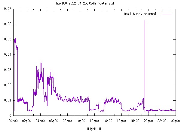
This is a diurnal plot of the 180 Hz mains harmonic for that day. Around 17:30 UT, Nathaniel and I removed the ground wire. The spike was when I momentarily disconnected and moved the earth ground connection (the other antenna electrode) from a ground spike to a ground clamp attached to the mast. After that, the 180 Hz harmonic is greatly reduced!
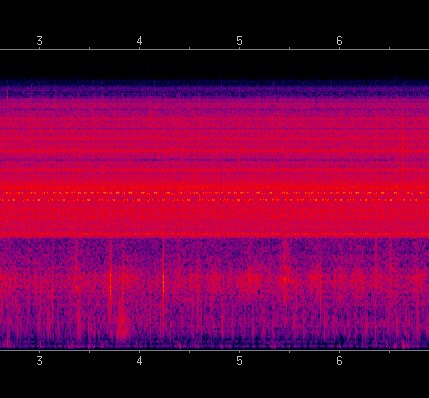
The difference is quite remarkable in the spectrogram too! Here is the spectrogram before the ground wire was removed:
And here is the spectrogram after the ground the ground wire was removed:
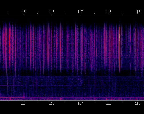
These were spectrograms were generated right before and after the ground wire was removed. As you can see, the reduction in mains harmonics is very noticeable! Aurally, it sounds so much better too!
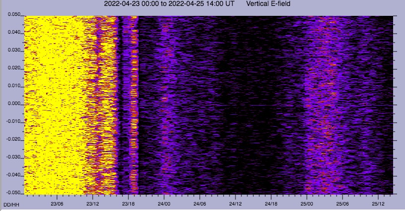
A side benefit is reliable reception of the amateur bands of 8720 Hz and 5170 Hz. Here are spectrograms centered at each of those frequencies. With detecting GPS referenced phase and frequency locked carriers and coherent BPSK, the reduction in mains harmonics will make QSOs possible now. Here is the spectrogram of 8720 Hz:
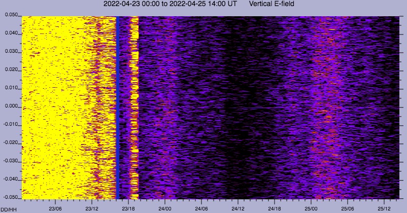
On the left is before the ground wire was removed, on the middle and right is after. A faint line can be observed 4/24 from 12:00-18:00UT. This is a harmonic due cross talk from the PPS signal inside the Raspberry Pi box.
To view this discussion on the web visit https://groups.google.com/d/msgid/hamsci/MW5PR13MB54644D5824902AA41F19CB91D0FC9%40MW5PR13MB5464.namprd13.prod.outlook.com.
Bob Gerzoff
Thanks for that great explanation.
To view this discussion on the web visit https://groups.google.com/d/msgid/hamsci/CAOY0kB1VyowKKPdbsuYKuvy6TjYuEfgia8-fadj_sQiWjYzB3g%40mail.gmail.com.
Julius Madey
Jules K2KGJ
To view this discussion on the web visit https://groups.google.com/d/msgid/hamsci/3554C876-0F3E-4661-B3E9-20602DB9D0BD%40gmail.com.