Path pursuit algorithm
615 views
Skip to first unread message

Michael Shimniok
May 9, 2013, 5:29:41 PM5/9/13
to diyr...@googlegroups.com
One of the things I need to do for 2013 AVC is to fix Data Bus' path
pursuit algorithm. It's been ~ a year since I looked at Ted's and
Jesse's algorithms. I think I ended up re-creating what Ted's doing.
(Ted?)
Last year I'd attempted to implement what a true Pure Pursuit* algorithm, however it had the disadvantage of blowing up when cross track error exceeded lookahead distance. Fun. The computations / concept was a bit of a brain stretch for me. This version is conceptually simpler for me.
Attached you'll find a Processing demo for the path pursuit algorithm I hope to use. The Processing script roughly approximates the 2013 waypoint locations, and starts the robot out at the starting line with a significant cross-track error in order to demonstrate how it handles that scenario. It corrects its position before the first waypoint and then the robot traverses the course over and over.
How it works:
The robot computes a point that is a projection of it's current position onto the current path (the line between the previous and next waypoints) and adds a lookahead distance along the path to find the goal point, the rabbit the robot chases around the course.
The robot computes the relative bearing to the rabbit, uses that to find an intercept circle to this point, and calculates a steering angle to traverse the intercept circle. The 'rabbit', intercept circle, and turning radius change at each update, of course. The result is fairly smooth steering correction and decent behavior over a wide range of heading and cross track errors.
I've not played with the parameters much but so far found a couple interesting things.
The target waypoint changes when the robot is less than a threshold distance to the waypoint. The lookahead distance seems to be best set below this threshold.
The robot automatically negotiates a reasonable turn when transitioning between waypoints, cutting the corner.
When I have 3 waypoints that describe a triangle with two very shallow angles, there's some weirdness at the waypoint transition. Shouldn't be too hard to fix.
After that I'll dink with the parameters a little more then I'll implement in the Data Bus code and see how it works in the real world.
Thoughts/input welcome.
Michael
---
* the distinction is that with pure pursuit, as I understand it, one solves for a point that is a fixed distance from the robot, lying along the desired path. That's subtly different than finding a point that is a fixed distance along the path from the projection of the robot's position onto the path.

Wayne Holder
May 9, 2013, 7:49:59 PM5/9/13
to diyr...@googlegroups.com
Michael, I use what I call Line Circle Intersect, which is basically the same approach you're talking about, in Johnny Five. In fact, to help visualize the intersect point the car steers toward, I wrote a simple Java Applet (which is actually coded with a main() method so you can run it as a standalone application.) I've attached the source code in case it might be useful to you.
Wayne--
You received this message because you are subscribed to the Google Groups "diyrovers" group.
To unsubscribe from this group and stop receiving emails from it, send an email to diyrovers+...@googlegroups.com.
To post to this group, send email to diyr...@googlegroups.com.
For more options, visit https://groups.google.com/groups/opt_out.

Ted Meyers
May 9, 2013, 8:20:40 PM5/9/13
to diyr...@googlegroups.com
Did I hear my name?
Okay, so my take on the pursuit algorithm is that you don't need to worry about the exact steering angle. It doesn't really matter as long as you do some steering; you might turn the wheels a lot if the desired heading is significantly different from the current heading and a little if close, but that's about all that is needed. What I'm saying here is that no intercept curve is required to be computed; the curve falls out of just turning the wheels in the right direction.
As far as computing a look-ahead point, what I did was compute one a based on the look-ahead distance from the current waypoint (or starting line). I then compute the distance from the bot to the point, if that falls below the threshold, I move the point towards the next waypoint. This means that if the bot wanders from the waypoint, the waypoint will stop advancing and the bot should head straight back to it and eventually get back on course. When the bot gets close to a waypoint, I increment the current waypoint, re-position the look-ahead point and continue on. This allows the bot to nicely cut corners. It sounds like this is quite close to your algorithm. I also think that this is closer to what Michael describes as true pure pursuit.
Ted
Ted Meyers
May 9, 2013, 8:22:19 PM5/9/13
to diyr...@googlegroups.com
Oh yeah, isn't Processing great for this type of thing, I love it!
Ted

Borna Emami (0x27)
May 9, 2013, 9:50:28 PM5/9/13
to diyr...@googlegroups.com
Michael,
I ran your simulation and it looks very interesting.
Are you simulating the control loop that sets your heading angle(Steers the car toward when you tell it to) or just assuming that the car is pointed at the target at all times?
If you are not simulating that then the simulations would not show you the "time delay" between setting the direction of the car and when the car actually gets there which can cause oscillations in the heading of the robot. To test this, you can just simulate it by adding a simple time delay of half a second or so.
Michael Shimniok
May 9, 2013, 10:08:56 PM5/9/13
to diyr...@googlegroups.com
Hey, I'm really glad you joined the group! Looking forward to seeing what 0x27 brings out this year! I didn't think I was quite up for the elevated challenge of doping; I'm in Peloton.
Anyway... no, the simulation is really simplistic. I'm not modeling servo delay or even ackerman steering. I don't even have any kind of proper scale set (1 pixel equals... I have no idea) :) I'll see if I can make the sim a little more sophisticated tonight...
Michael
Anyway... no, the simulation is really simplistic. I'm not modeling servo delay or even ackerman steering. I don't even have any kind of proper scale set (1 pixel equals... I have no idea) :) I'll see if I can make the sim a little more sophisticated tonight...
Michael
Michael Shimniok
May 10, 2013, 2:29:11 AM5/10/13
to diyr...@googlegroups.com
> Okay, so my take on the pursuit algorithm is that you don't need to
> worry about the exact steering angle. It doesn't really matter as
> long as you do some steering; you might turn the wheels a lot if the
> desired heading is significantly different from the current heading
> and a little if close, but that's about all that is needed. What I'm
> saying here is that no intercept curve is required to be computed; the
> curve falls out of just turning the wheels in the right direction.
I agree, it's not required in the slightest.
> worry about the exact steering angle. It doesn't really matter as
> long as you do some steering; you might turn the wheels a lot if the
> desired heading is significantly different from the current heading
> and a little if close, but that's about all that is needed. What I'm
> saying here is that no intercept curve is required to be computed; the
> curve falls out of just turning the wheels in the right direction.
But one still needs an algorithm to determine how far to turn the wheels
based on some error term (such as relative bearing to a moving goal point).
It could be a basic full left, zero, full right based on whether there's
error outside some dead band. Or you could have discrete levels. Or a
simple formula relating the error term to a servo signal. But how do you
determine that formula?
I didn't want to do a bunch of trial and error so I measured steering
angle versus servo signal, then set steering angle based on desired turn
radius which is based on the intercept circle. It worked the first time
out so I figured I'd keep it. :)
> As far as computing a look-ahead point, what I did was compute one a
> based on the look-ahead distance from the current waypoint (or
> starting line). I then compute the distance from the bot to the
> point, if that falls below the threshold, I move the point towards the
> next waypoint.
> This means that if the bot wanders from the waypoint, the waypoint
> will stop advancing and the bot should head straight back to it and
> eventually get back on course. When the bot gets close to a waypoint,
> I increment the current waypoint, re-position the look-ahead point and
> continue on. This allows the bot to nicely cut corners. It sounds
> like this is quite close to your algorithm. I also think that this is
> closer to what Michael describes as true pure pursuit.
each update, it finds a new point along the line that is lookahead
distance from the robot. So it's continually updating the lookahead point.
Our two algorithms are pretty similar except yours requires quite a bit
less computing. :)
Btw, I was able to revise my simulation to properly scale for real
distances and time. It looks like I'll need to spend more time revamping
the simulated turning.
Michael
Ted Meyers
May 10, 2013, 10:39:13 AM5/10/13
to diyr...@googlegroups.com
But one still needs an algorithm to determine how far to turn the wheels
based on some error term (such as relative bearing to a moving goal point).
It could be a basic full left, zero, full right based on whether there's
error outside some dead band. Or you could have discrete levels. Or a
simple formula relating the error term to a servo signal. But how do you
determine that formula?
Yeah, discrete levels is what I use, based on some tuneable parameters (from the heading delta). It's real simple, but I see your point.
How far do you move it? By the threshold distance you mention?
Sorry, I wasn't very clear there; the threshold is the lookahead distance and I move the point so that it is at the lookahead distance. Well, I cheat a bit and just move it by the amount that it is too close.
My recollection from reading a few papers on pure pursuit is that, at
each update, it finds a new point along the line that is lookahead
distance from the robot. So it's continually updating the lookahead point.
True, I took a shortcut here, it simplified the calculations, and kept the lookahead point from backtracking in the unlikely event that the bot got a long way away from the path (in which case, I figure that the actual lookahead point doesn't really matter much).
Our two algorithms are pretty similar except yours requires quite a bit
less computing. :)
Yeah, that's what I was going for.
Btw, I was able to revise my simulation to properly scale for real
distances and time. It looks like I'll need to spend more time revamping
the simulated turning.
That's awesome! I always have trouble getting real world scaling right. Be sure to put in some sources of error and bias in your simulation.
Ted
Ted Meyers
May 10, 2013, 10:46:59 AM5/10/13
to diyr...@googlegroups.com
If you are not simulating that then the simulations would not show you the "time delay" between setting the direction of the car and when the car actually gets there which can cause oscillations in the heading of the robot. To test this, you can just simulate it by adding a simple time delay of half a second or so.
Interesting point! In my simulations, I increment the steering in small units every iteration until it gets to the desired steering value. This doesn't really simulate any delay in when it actually starts to turn. Also, I probably still don't have enough delay; I suppose that in real life it does take as long as half a second to actually turn the wheels.
Michael Shimniok
May 11, 2013, 2:22:33 AM5/11/13
to diyr...@googlegroups.com
Cool Java program. Is your circle is tangential to the robot's heading? If so then we're doing the same thing.
I'll be posting a blog entry to explain my path following, circle intercept, and steering (which will cover Ackerman steering geometry -- it's pretty straightforward).
Here's a diagram explaining how I do circle intercept.
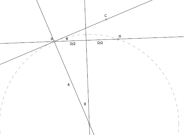
Robot is at B, goal point (rabbit) is at G at a distance D. Heading is described by BC. Relative bearing to G is Theta. The circle has radius R that intersects B and G and is tangential to BC. Looking at the geometry it turns out that the angle between the radius lines intersecting B and G is Theta, also. That means sin(theta) = (D/2)/R and you can solve for R = D/(2sin(Theta)). Note that the actual course path isn't shown in the picture above -- it isn't relevant, in fact.
Next, compute a steering angle to trace the selected turning radius. Ackerman geometry results in simple trig.
What I like best about these approaches is that the code is logically simple.
On a related note, I finally got the Processing sim working properly with a simulated steering dead band (slop) and steering delay based on realistic numbers.
Still playing with the delay parameters to see where oscillation comes into play...
The steering slop introduces some back and forth steering. Just like I had to do with my Jeep before I got the steering tightened up :)
Michael
<LineCircle.java>
Michael Shimniok
May 12, 2013, 12:28:49 AM5/12/13
to diyr...@googlegroups.com
On Thursday, May 9, 2013 7:50:28 PM UTC-6, Borna Emami (0x27) wrote:
If you are not simulating that then the simulations would not show you the "time delay" between setting the direction of the car and when the car actually gets there which can cause oscillations in the heading of the robot. To test this, you can just simulate it by adding a simple time delay of half a second or so.
Having done some playing with the numbers, I'm not as worried about oscillation due to slow servo.
Lower speeds, bigger turn threshold radius, and longer lookahead distance each place lighter demands on the servo. But even a fast robot negotiating tight turns won't oscillate steering if the lookahead distance is long enough. If my simulation is accurate, then the values I was using last year should be fine.
When the lookahead distance is too short, turn radii get too small, rate of change of commanded steering gets too high, and the servo just can't keep up when a new direction is requested, and, when relative bearing to the goal point rapidly approaches zero after a turn, the servo can't return the steering to center fast enough. increasing lookahead increases the minimum turning radius required and reduces the rate-of-change of relative bearing.
If the robot's path is overshooting the turns but the servo isn't lagging significantly, all that's required is increasing waypoint turn threshold to accommodate the commanded turn radius.
In terms of numbers, my servo (I think it's a Futaba S3003) has typical 60 deg per 0.19 sec performance. Steering swings 20 deg in one direction. Assuming even a 90 degree sweep required to change steering 40 degrees, the servo can accomplish lock to lock steering in 285ms. It can change steering angle by one degree every ~7ms so if the maximum steering angle commanded is 10 degrees (probably typical for the parameters I plan to use), the servo only takes 70ms to do this, during which time the control routine has been called only 7 times. I suppose at 10m/s the robot's traveled 70cm before the steering is caught up, but if the turn threshold is long enough, who cares?
There's kind of an advantage to a slow servo. In racing it's best to avoid sudden steering input changes. Traction breaking loose, rapid weight transfer, etc.
Borna Emami (0x27)
May 12, 2013, 4:02:41 AM5/12/13
to diyr...@googlegroups.com
True, if the look ahead distance is far enough ahead it will reduce the oscillation however it takes longer to get on track.
Although the servo has some "delay" it is sufficiently fast not to affect the rest of the system. the main thing I am worried about is how long does it take the car to point in the direction it is being commanded it.
And when I say delay, I mean dynamics. the closed loop car steering system with a PD controller is second order (a/(s^2+b*s+a)).
Michael Shimniok
May 12, 2013, 1:42:56 PM5/12/13
to diyr...@googlegroups.com
> the main thing I am worried about is how long does it take the car to point in the direction it is being commanded it.
I should mention that the simulation does show overshoot, ringing and a long settle time for both cross track error and relative bearing (heading error). Is that what you mean?
There's a delay in achieving a commanded turning radius. Perhaps this delay could be eliminated by path following variable radius arcs with radius rate of change that the steering system can keep up with...
> And when I say delay, I mean dynamics. the closed loop car steering system with a PD controller is second order (a/(s^2+b*s+a)).
From a practical standpoint I think I'll halt the simulation and see how it works in the real world.
Michael

Josh Pieper
May 13, 2013, 8:40:59 AM5/13/13
to diyr...@googlegroups.com
Michael Shimniok wrote:
> There's a delay in achieving a commanded turning radius. Perhaps
> this delay could be eliminated by path following variable radius
> arcs with radius rate of change that the steering system can keep up
> with...
When I have used pure-pursuit, I normally set the "look-ahead"
> There's a delay in achieving a commanded turning radius. Perhaps
> this delay could be eliminated by path following variable radius
> arcs with radius rate of change that the steering system can keep up
> with...
radius in terms of time, not distance. So you have a fixed look-ahead
time measured in seconds, and you multiply that by your current
speed to find the pure pursuit radius. As Borna pointed out, you
still need a minimum radius for low speeds.
All platforms have a limited bandwidth, both of the steering and
mechanical system, but sometimes also of the position and heading
estimation system. As long as you set the look-ahead time to be
sufficiently slower than the overall bandwidth, steering will be
stable at nearly any speed. For RC car platforms, normally you need
at least around a second of look-ahead, but this can be more or less
depending upon how strong your steering servo is, how much understeer
or oversteer you have, and your suspension characteristics.
One problem with pure pursuit is that it has difficulty accurately
tracking the path at high speeds. In fact, typical cross-track errors
will scale linearly with speed. Applying an integrative crosstrack
error term can be destabilizing, and in any case is not useful for
situations with fast dynamics. Another problem with this simple time
based formulation, is that rapid changes in speed can be destabilizing
as well. You can get around that by limiting the rate at which the
look-ahead radius can decrease.
I've been experimenting with an LQR based controller, which is what
we're using in our current autonomous runs. It theoretically is able
to maintain tracking accuracy at all speeds and through fast
maneuvers, but I don't have a good feel (or derivation) for the
stability characteristics of our current formulation. All I can say
is that it seems to work most of the time.
-Josh
http://joshp.no-ip.com:8080/
Michael Shimniok
May 13, 2013, 10:29:29 AM5/13/13
to diyr...@googlegroups.com
On 05/13/2013 06:40 AM, Josh Pieper wrote:
> When I have used pure-pursuit, I normally set the "look-ahead" radius
> in terms of time, not distance. So you have a fixed look-ahead time
> measured in seconds, and you multiply that by your current speed to
> find the pure pursuit radius. As Borna pointed out, you still need a
> minimum radius for low speeds.
I was just wondering about that last night, actually.
> When I have used pure-pursuit, I normally set the "look-ahead" radius
> in terms of time, not distance. So you have a fixed look-ahead time
> measured in seconds, and you multiply that by your current speed to
> find the pure pursuit radius. As Borna pointed out, you still need a
> minimum radius for low speeds.
> All platforms have a limited bandwidth, both of the steering and
> mechanical system, but sometimes also of the position and heading
> estimation system.
> As long as you set the look-ahead time to be
> sufficiently slower than the overall bandwidth, steering will be
> stable at nearly any speed.
are fine. But why the overshoot & ringing in heading err/cross track
err? It is characteristic of a step response. Where's the step? The
commanded turn radius instantly changes at the turn threshold.
I found a paper last night that discusses the use of continuous curves
comprised of straight lines, clothoids (Euler spirals, curves that with
curvature varying linearly with length), and constant radius arcs.
If the overshoot & ringing is bad enough in real life I will look into
some way to implement a continuous curvature for the robot to follow. Or
I might just do it anyway for the fun of it. This may sound odd but I'm
actually not all that motivated to work on the robot for the sake of
competing-- I'm way more motivated by learning and implementing
fascinating stuff like we're discussing in this thread.
> I've been experimenting with an LQR based controller, which is what
> we're using in our current autonomous runs.
deviations, with costs given weights) for a system with system dynamics
as a set of linear differential equations? Hm, that'd take me another
couple years to wrap my head around. :D
Michael
Josh Pieper
May 13, 2013, 5:01:11 PM5/13/13
to diyr...@googlegroups.com
Michael Shimniok wrote:
> So I guess that is the case here.. estimation system and servo
> bandwidth are fine. But why the overshoot & ringing in heading
> err/cross track err? It is characteristic of a step response.
> Where's the step? The commanded turn radius instantly changes at the
> turn threshold.
I've always implemented pure pursuit in the traditional way, with the
> So I guess that is the case here.. estimation system and servo
> bandwidth are fine. But why the overshoot & ringing in heading
> err/cross track err? It is characteristic of a step response.
> Where's the step? The commanded turn radius instantly changes at the
> turn threshold.
lookahead point a fixed distance away from the car. In this case, the
desired curvature never changes instantaneously, although you can
still have ringing at sharp corners.
You can implement this by just checking for the intersection of the
circle centered at the car with the current line segment and enough of
the subsequent ones to guarantee success. Circle-line segment
intersection formulas can be found pretty easily. I also force the
look ahead distance to be at least some >1.0x multiplier of the
crosstrack in addition to the overall minimum to prevent blowup.
> I found a paper last night that discusses the use of continuous
> curves comprised of straight lines, clothoids (Euler spirals, curves
> that with curvature varying linearly with length), and constant
> radius arcs.
>
> If the overshoot & ringing is bad enough in real life I will look
> into some way to implement a continuous curvature for the robot to
> follow. Or I might just do it anyway for the fun of it. This may
> sound odd but I'm actually not all that motivated to work on the
> robot for the sake of competing-- I'm way more motivated by learning
> and implementing fascinating stuff like we're discussing in this
> thread.
into shorter ones, then run an iterative smoother on them. There are
many valid approaches, a particularly easy one to implement was
described in Sebastian Thrun's Udacity class, Artificial Intelligence
for Robotics (specifically "Constrained Smoothing" described in the
second to last video below). That way your path following algorithm
doesn't need to change at all, it just has waypoints spaced more
closely together that approximate a smooth path.
The videos are just on youtube, the relevant ones are below:
https://www.youtube.com/watch?v=pjgfffzvbUg
https://www.youtube.com/watch?v=CHjsYzc_IwE
https://www.youtube.com/watch?v=9mOt7cnCxzo
https://www.youtube.com/watch?v=0I-8WJdkWrk
https://www.youtube.com/watch?v=YesKg2m9vng
https://www.youtube.com/watch?v=-fcwwzfKYjU
https://www.youtube.com/watch?v=v0-OUApP_5Q
https://www.youtube.com/watch?v=ffLPf8kI6qg
https://www.youtube.com/watch?v=a3whnj4H4DQ
https://www.youtube.com/watch?v=ApN4VxlueqM
> >I've been experimenting with an LQR based controller, which is what
> >we're using in our current autonomous runs.
>
> A Linear-Quadratic Regulator? Minimizing a cost function (describing
> deviations, with costs given weights) for a system with system
> dynamics as a set of linear differential equations? Hm, that'd take
> me another couple years to wrap my head around. :D
numerically. :)
-Josh
http://joshp.no-ip.com:8080/
Michael Shimniok
May 14, 2013, 5:27:45 PM5/14/13
to diyr...@googlegroups.com
> I've always implemented pure pursuit in the traditional way, with the
> lookahead point a fixed distance away from the car. In this case, the
> desired curvature never changes instantaneously, although you can
> still have ringing at sharp corners.
I found with path following 90 degree bends.
> You can implement this by just checking for the intersection of the
> circle centered at the car with the current line segment and enough of
> the subsequent ones to guarantee success. Circle-line segment
> intersection formulas can be found pretty easily.
think last time I gave up and worked on deriving an equation to find the
lookahead point on the path. Seems like I had it working fine in
simulation but ran into issues that I didn't have time to troubleshoot
last year.
On the other hand, I kind of like what I have. Aside from awkward corner
transitions, I'm not sure I see what the disadvantages really are at
this point. It has the advantage of being simple (at least for me) to
grasp the math and compute and it seems to work at least in
simulation... I was able to source a gearset locally so I hope to find
out about real world performance later today.
> I also force the look ahead distance to be at least some >1.0x
> multiplier of the crosstrack in addition to the overall minimum to
> prevent blowup.
I don't know, I kind of like my pseudo-pure pursuit for the moment. I'm
still debating what to do about corners and ringing.
I learned a bit about Bezier curves yesterday; guaranteed tangential to
the control (path) lines, provides curve continuity from straight line,
seems relatively simple to grasp the geometry, at least. Sounds like
goodness to me.
> One particularly easy route, is to supersample your long path segments
> into shorter ones, then run an iterative smoother on them.
went through the smoothing portions of the class. Very simple,
practical, straightforward. I may just go this route (ahem).
Supersampling and smoothing sounds like the best idea at this point. I
could do that offline so I can see where the robot will travel in Google
Earth.
I find it interesting that PID path following was taught in the class.
And, apparently, that's being used by the Google Car? I thought everyone
used pure pursuit or something like it?
>> A Linear-Quadratic Regulator? Minimizing a cost function (describing
>> deviations, with costs given weights) for a system with system
>> dynamics as a set of linear differential equations? Hm, that'd take
>> me another couple years to wrap my head around. :D
> It is easier than it sounds if you do all the derivatives
> numerically. :)
it, though, in all seriousness.
Michael

ab25...@gmail.com
Feb 18, 2018, 9:47:09 PM2/18/18
to diyrovers
INTERSECT LINES NOT MEETING....I'm hoping you guys are still around. I'm trying to implement Pure Pursuit. My problem is at various points the perpendicular lines from B and the BG midpoint do not intersect. Say for example the line I want to travel (FG) (not shown on your diagram) has a heading of 359 degrees. My rover (B) is on the left of the FG line with a cross track distance of -0.13 meters and the heading to G is 359.5. Since the rover is turning towards the FG line the rover reaches a point where its heading is 3 degrees. At this point the heading of my perpendicular line to the rover (B) is 93 (3+90). However my BG midpoint line has a heading of 89.5 (359.5+90). They will never intersect. What is broken in my logic? My look ahead variable is 35 meters and is regularly updated to move along line FG.
Al
Houston
Michael Shimniok
Feb 20, 2018, 7:42:37 AM2/20/18
to diyr...@googlegroups.com
We are still around :)
Also... Consider what happens to R as the angle BGF approaches 0.
I will probably have to draw out the scenario you are describing.
But I'm not near pencil and paper, so let me take a different tack by describing how the geometry is created to determine the turning radius required to intercept G.
You have any arbitrary goal point G, and a robot at position B with heading BC.
Draw a circle that intersects both B and G such that BC is tangential to the circle, because the robot can only follow a tangential arc from it's current position.
Now, solve for the radius of the circle.
You will probably need to add lines to do that. :) In fact, all the other lines in the diagram below are there to solve for R.
Note that the path FG isn't relevant to computing the turning radius to G.
To unsubscribe from this group and stop receiving emails from it, send an email to diyrovers+unsubscribe@googlegroups.com.
To view this discussion on the web visit https://groups.google.com/d/msgid/diyrovers/4b3c3984-22e7-45b7-833c-7f11331da244%40googlegroups.com.
For more options, visit https://groups.google.com/d/optout.
Reply all
Reply to author
Forward
0 new messages