DIY electroporator
826 views
Skip to first unread message

Marc Juul
Apr 27, 2016, 10:48:37 PM4/27/16
to diy...@googlegroups.com
I've found old threads on this list where people are discussing DIY electroporators but it doesn't seem like anyone published a new design since this expensive and impractical one from 1991:
http://www.biosci.missouri.edu/smithgp/PhageDisplayWebsite/electroporator.doc
Has anyone made anything better?http://www.biosci.missouri.edu/smithgp/PhageDisplayWebsite/electroporator.doc
Do biohackers actually use electroporation and if not, why not? What is your preferred transformation protocol for the organisms you work with.
--

Patrik D'haeseleer
Apr 28, 2016, 3:00:15 AM4/28/16
to DIYbio, ju...@labitat.dk
I do remember Nathan and some other folks discussing using piezo lighters to do electroporation. That would be the $2.97 version :-) Not sure how repeatable and standardized you could make that though.
Given how dirt cheap flyback transformers and other high voltage gear are on my favorite online discount site, perhaps that might be a better way to go.
Patrik
Marc Juul
Apr 28, 2016, 4:53:45 AM4/28/16
to Patrik D'haeseleer, DIYbio
On Thu, Apr 28, 2016 at 12:00 AM, Patrik D'haeseleer <pat...@gmail.com> wrote:
I do remember Nathan and some other folks discussing using piezo lighters to do electroporation. That would be the $2.97 version :-) Not sure how repeatable and standardized you could make that though.
Yeah I've looked at it and it might be worth trying. The voltage is in the right range but the pulse duration is much shorter than what I've seen mentioned in any electroporation protocol.
Given how dirt cheap flyback transformers and other high voltage gear are on my favorite online discount site, perhaps that might be a better way to go.
I have a pretty good idea how to build one but I wanted to check if this had already been done and if not if it is actually useful to anyone.
I'd probably use something like this:
to charge a bunch of 330v capacitors coupled both in parallel and serial (charge pump) to give something that can be charged in parallel to between 300v and 833v and discharged at between 300v and 2500v over a period of 0.1 ms to 5 ms using 2k5v solid state relays.
It'd be fairly easy to add conductance measurement to alert the user if spiking is likely to occur (e.g. too high salt content), which would have the bonus of making the electroporator double as a conductance meter.
It'd also be simple enough to add measurement of the discharge curve using a voltage divider and the built in ADC of an atmega chip.
Add an ESP8266 and you'd be able to connect via wifi+web to download and view the conductance measurement and discharge graph for use in your scientific article.
--
marc/juul

Nathan McCorkle
Apr 28, 2016, 4:13:09 PM4/28/16
to diybio
There was an unfortunate split of those conversations into another
mailing list (http://lists.cibolo.us/pipermail/open_electroporator/)
which subsequently crashed or something, and all content was lost
publicly. There was definitely more discussion on safety, pulse
shaping, pulse lengthening. I have these discussions still here in my
gmail account... but would need a few hours to sit down and back them
up, then convert and re-upload them somewhere (probably the diyhpl.us
git-powered wiki).
Is electroporation preferable? From the first time I used it, my first
summer internship, I was hooked. I thought "screw chemical
transformation" for the, in my opinion, more elegant, tuneable,
eco-friendly/greener-chemistry, faster, wider species coverage (you
just vary the pulse shape/voltage, maybe the salt content of the
buffer)... and higher efficiency to boot.
Why isn't it more prominent? Because no one has made a cheaper or
open-source version yet. If I'd have figured this out when I was still
in college, I probably would have built (at least) a unit for each lab
at school.
> --
> -- You received this message because you are subscribed to the Google Groups
> DIYbio group. To post to this group, send email to diy...@googlegroups.com.
> To unsubscribe from this group, send email to
> diybio+un...@googlegroups.com. For more options, visit this group at
> https://groups.google.com/d/forum/diybio?hl=en
> Learn more at www.diybio.org
> ---
> You received this message because you are subscribed to the Google Groups
> "DIYbio" group.
> To unsubscribe from this group and stop receiving emails from it, send an
> email to diybio+un...@googlegroups.com.
> To post to this group, send email to diy...@googlegroups.com.
> Visit this group at https://groups.google.com/group/diybio.
> To view this discussion on the web visit
> https://groups.google.com/d/msgid/diybio/CAL4ejvS3RGKA64x2a4uTOm19sAkM_REP3YMBBRJ_BfKZNGkqJA%40mail.gmail.com.
>
> For more options, visit https://groups.google.com/d/optout.
--
-Nathan
mailing list (http://lists.cibolo.us/pipermail/open_electroporator/)
which subsequently crashed or something, and all content was lost
publicly. There was definitely more discussion on safety, pulse
shaping, pulse lengthening. I have these discussions still here in my
gmail account... but would need a few hours to sit down and back them
up, then convert and re-upload them somewhere (probably the diyhpl.us
git-powered wiki).
Is electroporation preferable? From the first time I used it, my first
summer internship, I was hooked. I thought "screw chemical
transformation" for the, in my opinion, more elegant, tuneable,
eco-friendly/greener-chemistry, faster, wider species coverage (you
just vary the pulse shape/voltage, maybe the salt content of the
buffer)... and higher efficiency to boot.
Why isn't it more prominent? Because no one has made a cheaper or
open-source version yet. If I'd have figured this out when I was still
in college, I probably would have built (at least) a unit for each lab
at school.
> -- You received this message because you are subscribed to the Google Groups
> DIYbio group. To post to this group, send email to diy...@googlegroups.com.
> To unsubscribe from this group, send email to
> diybio+un...@googlegroups.com. For more options, visit this group at
> https://groups.google.com/d/forum/diybio?hl=en
> Learn more at www.diybio.org
> ---
> You received this message because you are subscribed to the Google Groups
> "DIYbio" group.
> To unsubscribe from this group and stop receiving emails from it, send an
> email to diybio+un...@googlegroups.com.
> To post to this group, send email to diy...@googlegroups.com.
> Visit this group at https://groups.google.com/group/diybio.
> To view this discussion on the web visit
> https://groups.google.com/d/msgid/diybio/CAL4ejvS3RGKA64x2a4uTOm19sAkM_REP3YMBBRJ_BfKZNGkqJA%40mail.gmail.com.
>
> For more options, visit https://groups.google.com/d/optout.
--
-Nathan
Nathan McCorkle
Apr 28, 2016, 4:14:16 PM4/28/16
to diybio
> It'd also be simple enough to add measurement of the discharge curve using a
> voltage divider and the built in ADC of an atmega chip.
>
> Add an ESP8266 and you'd be able to connect via wifi+web to download and
> view the conductance measurement and discharge graph for use in your
> scientific article.
ESP8266 has an ADC, so no need for an arduino/atmega, most likely.
> voltage divider and the built in ADC of an atmega chip.
>
> Add an ESP8266 and you'd be able to connect via wifi+web to download and
> view the conductance measurement and discharge graph for use in your
> scientific article.
--
-Nathan

Kermit Henson
Apr 29, 2016, 10:21:39 AM4/29/16
to DIYbio
Hi,
Maybe you already know about this paper, but here it goes
its a diy electroporator for 50usd.
the problem i see is that they use glass capillaries (yes, you can build a glass puller too T_T), but i think it may work for bacteria with some small modifications

William Beeson
Apr 29, 2016, 8:33:44 PM4/29/16
to DIYbio
All,
I am very interested in this topic. To transform filamentous fungi it is most practical to use electroporation. There are very few protocols that are established for chemical transformation. If anyone has ideas for how to get this to work well please post or share the ideas. The amount of electrical engineering involved in this is beyond my skill level.
-Will

John Griessen
Apr 30, 2016, 9:54:35 AM4/30/16
to diy...@googlegroups.com
On 04/29/2016 07:33 PM, William Beeson wrote:
> If anyone has ideas for how to get this to work well please post or share the ideas. The amount of electrical engineering
> involved in this is beyond my skill level.
Will you commit to some testing? Maybe 4 times on the same filamentous fungal cells? Over weeks with little
> If anyone has ideas for how to get this to work well please post or share the ideas. The amount of electrical engineering
> involved in this is beyond my skill level.
test circuit boards in the mail?
You're only interested in having this yesterday, so as soon as it works for you, the testing stops?
If it doesn't get going in a week, you're out?
William Beeson
Apr 30, 2016, 10:29:59 AM4/30/16
to DIYbio
I will test transformations on E.coli and Neurospora crassa. I've had interest in a low cost electroporator for months. I think the path to validation would be to show effectiveness with E. coli first (a much easier organism to transform). Then transition to fungal cells which have much lower transformation efficiency. If you have the hardware expertise to build a device with pre-programmed settings (say an E. coli and a fungal cells setting) I can do the lab work and prepare a data package for the product.
-Will
John Griessen
Apr 30, 2016, 11:56:48 PM4/30/16
to diy...@googlegroups.com
On 04/30/2016 09:29 AM, William Beeson wrote:
> I will test transformations on E.coli and Neurospora crassa. I've had interest in a low cost electroporator for months. I think
> the path to validation would be to show effectiveness with E. coli first (a much easier organism to transform). Then transition
> to fungal cells which have much lower transformation efficiency. If you have the hardware expertise to build a device with
> pre-programmed settings (say an E. coli and a fungal cells setting) I can do the lab work and prepare a data package for the product.
>
> -Will
>
> On Saturday, April 30, 2016 at 9:54:35 AM UTC-4, John Griessen wrote:
>
> On 04/29/2016 07:33 PM, William Beeson wrote:
> > If anyone has ideas for how to get this to work well please post or share the ideas. The amount of electrical engineering
> > involved in this is beyond my skill level.
How fast are you wanting this? I'm in the middle of another project.
> I will test transformations on E.coli and Neurospora crassa. I've had interest in a low cost electroporator for months. I think
> the path to validation would be to show effectiveness with E. coli first (a much easier organism to transform). Then transition
> to fungal cells which have much lower transformation efficiency. If you have the hardware expertise to build a device with
> pre-programmed settings (say an E. coli and a fungal cells setting) I can do the lab work and prepare a data package for the product.
>
> -Will
>
> On Saturday, April 30, 2016 at 9:54:35 AM UTC-4, John Griessen wrote:
>
> On 04/29/2016 07:33 PM, William Beeson wrote:
> > If anyone has ideas for how to get this to work well please post or share the ideas. The amount of electrical engineering
> > involved in this is beyond my skill level.
Anyone else interested in early testing of prototypes? These will be "junk prototypes".
Similar to DIY art assemblages, but a little neater, and documented so a product
could be made from them by a few revision iterations.
Message has been deleted

Koeng
May 1, 2016, 12:10:31 AM5/1/16
to DIYbio
I'd be interested in testing prototypes. I really like my current yeast transformation protocol because I find it easy enough, but I'd be very willing to test it out with E coli.

Jake
May 6, 2016, 10:33:36 AM5/6/16
to DIYbio, ju...@labitat.dk
Now I'm interested what the status of DIY electroporators is?
Saw some talk of ESP8266 and other ideas floating around. I've done a uC controlled flyback cap charger before, so I'm wondering what the actual technical difficulties are that remain?
Charge a cap to a couple kV, then switch it to the cell for the proper length of time with an IGBT? Anything I'm missing?
Marc Juul
May 7, 2016, 2:07:19 AM5/7/16
to Jake, DIYbio
On Fri, May 6, 2016 at 7:33 AM, Jake <jake...@mail.com> wrote:
Now I'm interested what the status of DIY electroporators is?Saw some talk of ESP8266 and other ideas floating around. I've done a uC controlled flyback cap charger before, so I'm wondering what the actual technical difficulties are that remain?Charge a cap to a couple kV, then switch it to the cell for the proper length of time with an IGBT? Anything I'm missing?
I started reading up on it. It looks like you want to be able to apply a voltage between 800v and 2.5 kV with a time delay between 1 ms and 5 ms, at least for e.coli and yeast. It sounds like there might be other types of cells that need lower voltages and lower time delays. Need to read up on this.
I'm still trying to figure out if the voltage discharge curve matters. If it doesn't then it might be possible to skip the capacitors completely and instead use a couple of transformers with multiple taps for different voltages and a
I outlined a possible design that would cost less than $100 in a previous recent thread on this list.
It would be _very_ beneficial to include conductance measurement so you can prevent the electroporator from firing when there's a chance of spiking. Conductance measurement is simple enough that it should be both easy and cheap to add.
You can get cheap 2.5 kV mosfet relays capable of switching at up to 0.1 ms speeds:
http://www.newark.com/mosfet-solid-state-relays/isolation-voltage/2-5kv/pg/810032199
--
http://www.newark.com/mosfet-solid-state-relays/isolation-voltage/2-5kv/pg/810032199
--
marc/juul
Nathan McCorkle
May 7, 2016, 7:30:10 AM5/7/16
to diybio
On Fri, May 6, 2016 at 11:07 PM, Marc Juul <ju...@labitat.dk> wrote:
> I'm still trying to figure out if the voltage discharge curve matters.
I can say there are certainly a lot of journal articles talking about
> I'm still trying to figure out if the voltage discharge curve matters.
pulse shape.
Random idea: if you hooked up a music input such that the amplitude
modulation was the electroporation pulse waveform, test different
music for efficacy, determine any relationships between music/genre
and species.
-Nathan
Jake
May 8, 2016, 1:46:12 AM5/8/16
to DIYbio
Should be easy enough to get rough square, trap., and sin pulses with just some passives on a 3-way switch. Marc suggested this...
Way easier to order something for $10 than making it up yourself. Other than that switch it with an arduino for the pulse length. Push a button... beep... beep... bam!

Alexey Zaytsev
May 8, 2016, 4:04:54 AM5/8/16
to diy...@googlegroups.com, Juanma García, Senzeni Pamela Mpofu
Hey,
sorry, late to the discussion.
Please take a look at the draft for an open source electroporator design from the Open Science Tools project:
A cheaper version with just 1 capacitance setting should also be possible.
I'm not actively working on it right now, but we will definitely get back to it sooner rather than later. And it's open source, so if you know enough about electronics, you are always welcome to contribute, just ping me.
Overall are working on developing low-cost open-source lab equipment, mainly for education, to teach molecular biology in your average school. But science enthusiasts are also a priority of course. The project is based in Shenzhen, China and Paris, France. I'll try to keep you updated with more news, but just drop me a message if you are interested in updates, or in working with us.
--
-- You received this message because you are subscribed to the Google Groups DIYbio group. To post to this group, send email to diy...@googlegroups.com. To unsubscribe from this group, send email to diybio+un...@googlegroups.com. For more options, visit this group at https://groups.google.com/d/forum/diybio?hl=en
Learn more at www.diybio.org
---
You received this message because you are subscribed to the Google Groups "DIYbio" group.
To unsubscribe from this group and stop receiving emails from it, send an email to diybio+un...@googlegroups.com.
To post to this group, send email to diy...@googlegroups.com.
Visit this group at https://groups.google.com/group/diybio.
To view this discussion on the web visit https://groups.google.com/d/msgid/diybio/d9aa3a72-befb-4d63-b214-0fe63bed22a7%40googlegroups.com.

nisha p
Feb 21, 2018, 8:37:38 AM2/21/18
to DIYbio
is this group still active?am trying to make electroporator with mosfet as switching element and high voltade dc power supply. I have kind of designed it .But power electronics is not my forte .can someone help me with it??
thankyou
John Griessen
Feb 21, 2018, 1:50:43 PM2/21/18
to diy...@googlegroups.com
On 02/20/2018 08:08 AM, nisha p wrote:
> is this group still active?am trying to make electroporator with mosfet as switching element and high voltade dc power supply. I
> have kind of designed it .But power electronics is not my forte .can someone help me with it??
> thankyou
there's this OSHW: https://github.com/kanzure/culture_shock
> is this group still active?am trying to make electroporator with mosfet as switching element and high voltade dc power supply. I
> have kind of designed it .But power electronics is not my forte .can someone help me with it??
> thankyou
and this list to discuss it on:
https://cibolo.us/mailman/listinfo/open_electroporator
I need to keep a focus on moving the project along, but can give you ideas, some review.
For instance, if above you mean to switch the output of the (2 kV purchased) HVDC supply, that won't work.
No chip MOSFETs can take that kind of voltage. Voltage like that needs to be spread out over space,
since it is enough to break down surfaces of insulators and make conductive tracks -- it will even break down
air over short distances like .2mm.
If you are making one for a voltage like 300V, then yes there are MOSFETs available, but 300V will apply only
to very small gaps between electrodes to get the needed field strength.

Gordana Ostojic
Feb 21, 2018, 6:05:40 PM2/21/18
to DIYbio
I don't know how much current (power) is needed. If not much you can try to find step-up high voltage generator on ebay. They are very cheap but voltage stability is not the best. Good luck and be careful.
On Wednesday, February 21, 2018 at 7:37:38 AM UTC-6, nisha p wrote:
is this group still active?am trying to make electroporator with mosfet as switching element and high voltade dc power supply. I have kind of designed it .But power electronics is not my forte .can someone help me with it??
th
nisha p
Feb 22, 2018, 3:26:12 AM2/22/18
to diy...@googlegroups.com
can anyone tell me about the minimum resistance on load present during electroporation and how much current will be drawn
--
-- You received this message because you are subscribed to the Google Groups DIYbio group. To post to this group, send email to diy...@googlegroups.com. To unsubscribe from this group, send email to diybio+unsubscribe@googlegroups.com. For more options, visit this group at https://groups.google.com/d/forum/diybio?hl=en
Learn more at www.diybio.org
---
You received this message because you are subscribed to a topic in the Google Groups "DIYbio" group.
To unsubscribe from this topic, visit https://groups.google.com/d/topic/diybio/D9AJmtyXqPg/unsubscribe.
To unsubscribe from this group and all its topics, send an email to diybio+unsubscribe@googlegroups.com.
To post to this group, send email to diy...@googlegroups.com.
Visit this group at https://groups.google.com/group/diybio.
To view this discussion on the web visit https://groups.google.com/d/msgid/diybio/03e22a92-f1e4-4fc8-9f76-3a7c5b7ac464%40googlegroups.com.
John Griessen
Feb 22, 2018, 12:30:42 PM2/22/18
to diy...@googlegroups.com
On 02/21/2018 10:34 PM, nisha p wrote:
> can anyone tell me about the minimum resistance on load present during electroporation and how much current will be drawn
>
Depends on size, volume.
> can anyone tell me about the minimum resistance on load present during electroporation and how much current will be drawn
>
nisha p
Feb 27, 2018, 11:41:59 PM2/27/18
to DIYbio
if it's a normal
4mm electroporation cuvette, 100 ul
4mm electroporation cuvette, 100 ul
John Griessen
Mar 9, 2018, 10:29:42 AM3/9/18
to electroporator function and design discussion, diy...@googlegroups.com
spaces apart 1mm or 2mm. We shoot for a voltage of 2100V by design across a 1mm gap filled to 10mm high, (half full).
That corresponds to a volume of 100 ul.
The culture shock electroporator is aimed at bacterial cells without the conductivity of normal saline or blood, so our
target resistance has been chosen for empirical e. coli. results in the past: about 30k Ohms for a length o 1/10 the area.
The cuvette we use has A = 10, l = 1 as in the diagram of resistivity below:
https://en.wikipedia.org/wiki/Electrical_resistivity_and_conductivity
so our R = 30k Ohms (arbitrary choice), and our resistivity is rho = RA/l = (30k)(10)/1 = 300k Ohm-meters.
The 300k Ohm-meters will apply to any shape of cuvette, and any fill level. That resistivity can be zapped
by the culture shock without pulling down the voltage below efficacious levels, (e.g. below 2100V @ 1mm gap for e. coli.).
What resistivity of cell suspension do you want to zap?
nisha p
Mar 17, 2018, 1:05:09 PM3/17/18
to diy...@googlegroups.com
Hi
I am just making a prototype ,so i haven't yet decided which protocol will follow yet.I have biorad 1mm,2mm cuvettes.And sir can you explain to me why in some electroporator circuits capacitor is in series with cuvette and in other, they are in parallel?Thank you so much for your patience and guidance--
-- You received this message because you are subscribed to the Google Groups DIYbio group. To post to this group, send email to diy...@googlegroups.com. To unsubscribe from this group, send email to diybio+unsubscribe@googlegroups.com. For more options, visit this group at https://groups.google.com/d/forum/diybio?hl=en
Learn more at www.diybio.org
--- You received this message because you are subscribed to a topic in the Google Groups "DIYbio" group.
To unsubscribe from this topic, visit https://groups.google.com/d/topic/diybio/D9AJmtyXqPg/unsubscribe.
To unsubscribe from this group and all its topics, send an email to diybio+unsubscribe@googlegroups.com.
To post to this group, send email to diy...@googlegroups.com.
Visit this group at https://groups.google.com/group/diybio.
To view this discussion on the web visit https://groups.google.com/d/msgid/diybio/77f61d8b-a745-4f12-7f6f-efabc32800f3%40industromatic.com.
John Griessen
Mar 17, 2018, 2:01:48 PM3/17/18
to diy...@googlegroups.com
On 03/17/2018 11:57 AM, nisha p wrote:
> I am just making a prototype ,so i haven't yet decided which protocol will follow yet.I have biorad 1mm,2mm cuvettes.And sir can
> you explain to me why in some electroporator circuits capacitor is in series with cuvette and in other, they are in parallel?
If they seem to be parallel or series they may be for different purpose. If in parallel, they could be shaping the pulse.
> I am just making a prototype ,so i haven't yet decided which protocol will follow yet.I have biorad 1mm,2mm cuvettes.And sir can
> you explain to me why in some electroporator circuits capacitor is in series with cuvette and in other, they are in parallel?
If in series, they could be storing energy to be dumped by a big knife switch with huge sparks, or they could be for pulse shaping
also. A big knife switch is good for movies like Frankenstein, but not necessary and generates lots of radio interference,
so not used in real life.
Mine works with output caps some parallel, some series to make a volt doubler. The transformer turns ratio gets output to 1500V
and doubler approaches 3kV, but does not get all the way there because of losses.
What circuits are you reverse engineering? Old Bio-Rad?
Nathan McCorkle
Mar 18, 2018, 3:47:45 AM3/18/18
to diybio
On Sat, Mar 17, 2018, 11:01 AM John Griessen <jo...@industromatic.com> wrote:
A big knife switch is good for movies like Frankenstein, but not necessary and generates lots of radio interference,
so not used in real life.
What circuits are you reverse engineering? Old Bio-Rad?
The biorad micropulser I took apart years ago had SCRs (silicon controlled rectifiers) in to switch the high-voltage as I recall.
nisha p
Mar 27, 2018, 10:02:07 AM3/27/18
to diy...@googlegroups.com
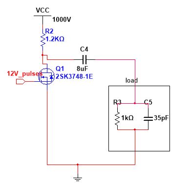
sorry for the late reply.No i am building from scratch with an external power supply.I have enclosed the diagram of circuit .the resistor R2 value I cant figure out how to calculate and its wattage.I took this value randomly from papers I read.The power supply I will be using is glassman power supply which can supply output voltage=0-40KV and output current =1mA
--
-- You received this message because you are subscribed to the Google Groups DIYbio group. To post to this group, send email to diy...@googlegroups.com. To unsubscribe from this group, send email to diybio+unsubscribe@googlegroups.com. For more options, visit this group at https://groups.google.com/d/forum/diybio?hl=en
Learn more at www.diybio.org
--- You received this message because you are subscribed to a topic in the Google Groups "DIYbio" group.
To unsubscribe from this topic, visit https://groups.google.com/d/topic/diybio/D9AJmtyXqPg/unsubscribe.
To unsubscribe from this group and all its topics, send an email to diybio+unsubscribe@googlegroups.com.
To post to this group, send email to diy...@googlegroups.com.
Visit this group at https://groups.google.com/group/diybio.
To view this discussion on the web visit https://groups.google.com/d/msgid/diybio/ded21fce-768f-8f49-3a7f-c282c7ea447f%40industromatic.com.
Nathan McCorkle
Mar 27, 2018, 12:08:35 PM3/27/18
to diybio
Hi Nisha,
You need to measure the resistance of your cell solution to calculate the load.
On Tue, Mar 27, 2018, 7:02 AM nisha p <nisha.p...@gmail.com> wrote:
sorry for the late reply.No i am building from scratch with an external power supply.I have enclosed the diagram of circuit .the resistor R2 value I cant figure out how to calculate and its wattage.I took this value randomly from papers I read.The power supply I will be using is glassman power supply which can supply output voltage=0-40KV and output current =1mA
On Sat, Mar 17, 2018 at 11:31 PM, John Griessen <jo...@industromatic.com> wrote:
On 03/17/2018 11:57 AM, nisha p wrote:
I am just making a prototype ,so i haven't yet decided which protocol will follow yet.I have biorad 1mm,2mm cuvettes.And sir can you explain to me why in some electroporator circuits capacitor is in series with cuvette and in other, they are in parallel?
If they seem to be parallel or series they may be for different purpose. If in parallel, they could be shaping the pulse.
If in series, they could be storing energy to be dumped by a big knife switch with huge sparks, or they could be for pulse shaping also. A big knife switch is good for movies like Frankenstein, but not necessary and generates lots of radio interference,
so not used in real life.
Mine works with output caps some parallel, some series to make a volt doubler. The transformer turns ratio gets output to 1500V and doubler approaches 3kV, but does not get all the way there because of losses.
What circuits are you reverse engineering? Old Bio-Rad?
--
-- You received this message because you are subscribed to the Google Groups DIYbio group. To post to this group, send email to diy...@googlegroups.com. To unsubscribe from this group, send email to diybio+un...@googlegroups.com. For more options, visit this group at https://groups.google.com/d/forum/diybio?hl=en
Learn more at www.diybio.org
--- You received this message because you are subscribed to a topic in the Google Groups "DIYbio" group.
To unsubscribe from this topic, visit https://groups.google.com/d/topic/diybio/D9AJmtyXqPg/unsubscribe.
To unsubscribe from this group and all its topics, send an email to diybio+un...@googlegroups.com.
To post to this group, send email to diy...@googlegroups.com.
Visit this group at https://groups.google.com/group/diybio.
To view this discussion on the web visit https://groups.google.com/d/msgid/diybio/ded21fce-768f-8f49-3a7f-c282c7ea447f%40industromatic.com.
--
-- You received this message because you are subscribed to the Google Groups DIYbio group. To post to this group, send email to diy...@googlegroups.com. To unsubscribe from this group, send email to diybio+un...@googlegroups.com. For more options, visit this group at https://groups.google.com/d/forum/diybio?hl=en
Learn more at www.diybio.org
---
You received this message because you are subscribed to the Google Groups "DIYbio" group.
To unsubscribe from this group and stop receiving emails from it, send an email to diybio+un...@googlegroups.com.
To post to this group, send email to diy...@googlegroups.com.
Visit this group at https://groups.google.com/group/diybio.
To view this discussion on the web visit https://groups.google.com/d/msgid/diybio/CAPR%2BG_1LzxZsG4PLOpT-z3d4Jk7drjnWMwGAdP2uoxq3y2B5sQ%40mail.gmail.com.
John Griessen
Mar 27, 2018, 1:32:12 PM3/27/18
to diy...@googlegroups.com
On 03/27/2018 08:18 AM, nisha p wrote:
> I have enclosed the diagram of circuit
That will put a symmetric AC spikish wave on your output.
> I have enclosed the diagram of circuit
It will look like (+)spike,zero, (-)spike, zero repeating.
And the spikes will be at high voltage until you hit the limit of the transistor and it quits.
That means lots of radio waves -- an inconsiderate way to go, and may stop some other gear in your lab from working
if you time it right.
nisha p
Mar 28, 2018, 5:52:00 AM3/28/18
to diy...@googlegroups.com
i will measure resistance today.what should I add in this circuit to get pulses i require.
thank you for your help
--
-- You received this message because you are subscribed to the Google Groups DIYbio group. To post to this group, send email to diy...@googlegroups.com. To unsubscribe from this group, send email to diybio+unsubscribe@googlegroups.com. For more options, visit this group at https://groups.google.com/d/forum/diybio?hl=en
Learn more at www.diybio.org
--- You received this message because you are subscribed to a topic in the Google Groups "DIYbio" group.
To unsubscribe from this topic, visit https://groups.google.com/d/topic/diybio/D9AJmtyXqPg/unsubscribe.
To unsubscribe from this group and all its topics, send an email to diybio+unsubscribe@googlegroups.com.
To post to this group, send email to diy...@googlegroups.com.
Visit this group at https://groups.google.com/group/diybio.
To view this discussion on the web visit https://groups.google.com/d/msgid/diybio/676d545f-7bbd-ea10-dbf7-178c8599bb0e%40industromatic.com.
nisha p
Mar 28, 2018, 7:25:14 AM3/28/18
to diy...@googlegroups.com
PS: what type of energy storage capacitors should i opt for metalized propylene or ceramic capacitors
John Griessen
Mar 28, 2018, 12:26:59 PM3/28/18
to diy...@googlegroups.com
On 03/28/2018 06:25 AM, nisha p wrote:
> PS: what type of energy storage capacitors should i opt for metalized propylene or ceramic capacitors
>
> PS: what type of energy storage capacitors should i opt for metalized propylene or ceramic capacitors
>
> On Wed, Mar 28, 2018 at 3:21 PM, nisha p <nisha.p...@gmail.com <mailto:nisha.p...@gmail.com>> wrote:
>
> i will measure resistance today.what should I add in this circuit to get pulses i require.
> thank you for your help
I've pointed you to my open hardware project before. These kinds of vague questions would be better asked on
>
> i will measure resistance today.what should I add in this circuit to get pulses i require.
> thank you for your help
the list for that project rather than diybio. The hardware details and many possible directions would bore many on this list.
Here's a link to the list: https://cibolo.us/mailman/listinfo/open_electroporator
Culture shock is not really a DIY design, but maybe you can take parts and reuse for a super simple version
using your 1500V transistor and a metal shield around it to block its high radio noise.
I think the FCC rules even allow unintentional radiators that are intermittent firing.
I have not gone in that direction because I am sure it would be more laborious to build
and have higher material costs, so not good as a product.

Tom Knight
Mar 28, 2018, 1:10:10 PM3/28/18
to diy...@googlegroups.com, Thomas Knight
My main reason for reading this group is to help people avoid hurting themselves. Please think through this project. High voltage, especially high voltage with large capacitors, is very dangerous. I’d be happy to look over a design, but there are lots of ways to kill yourself with the components you are looking at.
> --
> -- You received this message because you are subscribed to the Google Groups DIYbio group. To post to this group, send email to diy...@googlegroups.com. To unsubscribe from this group, send email to diybio+un...@googlegroups.com. For more options, visit this group at https://groups.google.com/d/forum/diybio?hl=en
> Learn more at www.diybio.org
> --- You received this message because you are subscribed to the Google Groups "DIYbio" group.
> To unsubscribe from this group and stop receiving emails from it, send an email to diybio+un...@googlegroups.com.
> To post to this group, send email to diy...@googlegroups.com.
> Visit this group at https://groups.google.com/group/diybio.
> To view this discussion on the web visit https://groups.google.com/d/msgid/diybio/c37c9b41-c9f5-b0e1-e04b-77e9261fd7c7%40industromatic.com.
> Visit this group at https://groups.google.com/group/diybio.
nisha p
Mar 29, 2018, 1:02:30 AM3/29/18
to diy...@googlegroups.com
if not 1000 V i would like to build a prototype at least for 300V or so as I have already committed to it.Thank you for your concern and patience for helping .if the questions pertaining to my project is going to bore the group ,I will not ask .but if someone can really guide a student like me I would greatly appreciate it .you can message me personally .once again thankyou for your time
On Wed, Mar 28, 2018 at 10:40 PM, Tom Knight <t...@mit.edu> wrote:
My main reason for reading this group is to help people avoid hurting themselves. Please think through this project. High voltage, especially high voltage with large capacitors, is very dangerous. I’d be happy to look over a design, but there are lots of ways to kill yourself with the components you are looking at.
> On Mar 28, 2018, at 12:26 PM, John Griessen <jo...@industromatic.com> wrote:
>
> On 03/28/2018 06:25 AM, nisha p wrote:
>> PS: what type of energy storage capacitors should i opt for metalized propylene or ceramic capacitors
>> On Wed, Mar 28, 2018 at 3:21 PM, nisha p <nisha.p...@gmail.com <mailto:nisha.puthukudi@gmail.com>> wrote:
>> i will measure resistance today.what should I add in this circuit to get pulses i require.
>> thank you for your help
>
> I've pointed you to my open hardware project before. These kinds of vague questions would be better asked on
> the list for that project rather than diybio. The hardware details and many possible directions would bore many on this list.
>
> Here's a link to the list: https://cibolo.us/mailman/listinfo/open_electroporator
>
> Culture shock is not really a DIY design, but maybe you can take parts and reuse for a super simple version
> using your 1500V transistor and a metal shield around it to block its high radio noise.
> I think the FCC rules even allow unintentional radiators that are intermittent firing.
>
> I have not gone in that direction because I am sure it would be more laborious to build
> and have higher material costs, so not good as a product.
>
> --
> -- You received this message because you are subscribed to the Google Groups DIYbio group. To post to this group, send email to diy...@googlegroups.com. To unsubscribe from this group, send email to diybio+unsubscribe@googlegroups.com. For more options, visit this group at https://groups.google.com/d/forum/diybio?hl=en
> Learn more at www.diybio.org
> --- You received this message because you are subscribed to the Google Groups "DIYbio" group.
> To unsubscribe from this group and stop receiving emails from it, send an email to diybio+unsubscribe@googlegroups.com.
> To post to this group, send email to diy...@googlegroups.com.
> Visit this group at https://groups.google.com/group/diybio.
> To view this discussion on the web visit https://groups.google.com/d/msgid/diybio/c37c9b41-c9f5-b0e1-e04b-77e9261fd7c7%40industromatic.com.
> For more options, visit https://groups.google.com/d/optout.
--
-- You received this message because you are subscribed to the Google Groups DIYbio group. To post to this group, send email to diy...@googlegroups.com. To unsubscribe from this group, send email to diybio+unsubscribe@googlegroups.com. For more options, visit this group at https://groups.google.com/d/forum/diybio?hl=en
Learn more at www.diybio.org
---
You received this message because you are subscribed to a topic in the Google Groups "DIYbio" group.
To unsubscribe from this topic, visit https://groups.google.com/d/topic/diybio/D9AJmtyXqPg/unsubscribe.
To unsubscribe from this group and all its topics, send an email to diybio+unsubscribe@googlegroups.com.
To post to this group, send email to diy...@googlegroups.com.
Visit this group at https://groups.google.com/group/diybio.
To view this discussion on the web visit https://groups.google.com/d/msgid/diybio/26434A31-47E5-4A8E-B99C-CF380DFBC61E%40mit.edu.
Nathan McCorkle
Mar 29, 2018, 3:09:02 PM3/29/18
to diybio
On Wed, Mar 28, 2018 at 10:02 PM, nisha p <nisha.p...@gmail.com> wrote:
if the questions pertaining to my project is going to bore the group ,I will not ask .but if someone can really guide a student like me I would greatly appreciate it .you can message me personally .once again thankyou for your time
No one here will be bored, John was merely saying there is a more-appropriate discussion forum, which is completely devoted to open-source electroporation development discussion.
Have you read through all the archived electroporation threads/discussions for this DIYbio group? There are years worth of discussions, articles, circuit investigations... all about electroporation.
Reply all
Reply to author
Forward
0 new messages